Practical Project Management Tips, Tactics, and Tools phần 3 pptx
Bạn đang xem bản rút gọn của tài liệu. Xem và tải ngay bản đầy đủ của tài liệu tại đây (275.79 KB, 40 trang )
CHAPTER 2.2
DO YOU WEEBIS?
CLARIFYING WBS, OBS, AND RBS
60
E
very discipline has its alphabet soup, abbreviations or acronyms for seemingly
nonmistakable terms and functions. In project management, we have the
WBS, OBS, and RBS, which, of course, everyone clearly understands. Right? It
should only be that simple.
The truth is that these terms have been applied somewhat loosely within the
project management community and by the popular project management soft-
ware packages. Sometimes, new terms are introduced to replace the basic three,
and even worse, these basic terms are being applied to functions that differ from
the traditional concepts.
In some cases, this deviation may primarily be a careless application of the
wrong term or willingness to stray from the traditional concept. In other, more
deleterious cases, the misuse of the terms will make it appear that the product has
capabilities that are not present. For instance, the availability of a data field that
contains an activity tag number called WBS does not necessarily mean that the
product has a true WBS capability.
Trap Any full WBS-type function (including OBS or RBS) must
be able to facilitate data summarization and reporting by
these codes, to any level. Using WBS codes solely for sorting
and selecting (filters) does not constitute a WBS function.
TEAMFLY
Team-Fly
®
Outlines and Other Frameworks
Fearing that many of us need something more simple and visual than WBS type
structures, several project management software developers, especially at the low
end, focus on an Outline mode. This provides a practical and very readable
method of defining and displaying a hierarchical relationship of individual tasks
within a larger project (and everyone knows what an outline is). It works, but with
limitations. The biggest constraint is that the outline provides only one project hi-
erarchy, when there may be several. For instance, the project manager may wish
to view the project using a work breakdown based on the phases of the project, or
geographical divisions, or perhaps deliverables. A functional manager is often
more interested in an outline that reflects the organizational structure, such as di-
vision, department, section, discipline. The corporate comptroller may wish to
segment and interrogate the data based on a code of accounts. So you can see that
a single outline may not do the job for everyone.
Not to worry! Many of the project management packages provide multiple
code fields for this multiple outline function. Some confusion has been gener-
ated by this expansion of outline fields. In an attempt to expand upon the hierar-
chical capabilities of the software, and to create some standard terminology, the
market has produced a set of new terms and formats. However, these are any-
thing but standard.
In order to facilitate frameworks for project plans (a very useful function), we
have created the Work Breakdown Structure (WBS), the Organization Break-
down Structure (OBS), and the Resource Breakdown Structure (RBS). One of
my clients referred to them as the Weebis, Obis, and Reebis (which, once you
stop laughing, is easier to say). But! These terms, as they are being used, do not
always mean the same thing.
What to Look For
Ordinarily, we would expect the outliner function to provide a summarization ca-
pability. That is, we expect the project data to be able to be rolled-up to the vari-
ous outline levels. This is almost universally true, for all outliners. We would
expect similar capabilities from a WBS. But, look out! Occasionally, you will come
across a WBS function wherein the WBS numbers are used solely as IDs, rather
than summarization points. In this case, the term WBS is really misapplied, as the
field is nothing more than an auxiliary code field. You will run into this situation
primarily in a few low-end products, where the outline based products are trying
to appear to have WBS functionality.
A larger problem is the varied use of the term OBS (see definitions). It can
WHAT TO LOOK FOR 61
mean two very different things. In fact, I once found the terms to be used quite
differently in two products being distributed by the same project management
software vendor.
To set the stage for a clarification of these terms, and their use, it is important
to establish a clear understanding of a basic premise of project data. Two basic ar-
eas are defined and managed. One is the work itself, consisting of the project(s)
and the tasks that are to be accomplished within the project. The other is the re-
sources that are going to accomplish the work. It is very important to recognize
this distinction. All project management software is based on this protocol. There
is task information, and there is resource (and cost) information. We need to
make the distinction between frameworks for the work (tasks) and frameworks
for the resource data.
Definitions
• The Outline, for those programs using this mode as the primary (or only)
framework, is always a work (task) framework.
• The WBS is fairly clear cut. It is essentially the same thing as the Outline. It
is the primary hierarchy for the tasks within a project. It applies to the work,
as opposed to the resources. When there are multiple WBSs, they are
merely additional codes applied to the list of tasks to facilitate multiple
sorts, filters, and summarization hierarchies.
• The RBS applies to the resources. It provides a basis for defining a parent
group for each resource (perhaps all resources within a specific discipline).
For instance, we might have Tom, Joan, and Iris, who are mechanical de-
signers. The parent category would be Mechanical Engineering and Design,
which, in turn, is a part of the Corporate Engineering and Design Function.
• The problem child in this alphabet soup is the OBS. Sometimes, it is set up
to be the exact same function as the RBS. In other words, it is an RBS that
is called an OBS. Other times it is set up to be a second variation of the
WBS (as we noted, it is quite normal for there to be several WBS-type hi-
erarchies). There is certainly a significant difference in these two concepts,
as the RBS should be used only for the resource data, whereas the OBS
(according to the most popular accepted practice) is intended solely for
task data.
Last, about these definitions, I will again state that a true WBS, OBS, or RBS
must be able to facilitate data summarization and reporting by these codes, to any
level. Using WBS codes for sorting and selecting does not constitute a WBS func-
62 DO YOU WEEBIS? CLARIFYING WBS, OBS, AND RBS
tion. Having a data field to designate a group for resources (even if called RBS or
Resource Outline) is not an RBS if it does not allow you to look at resource as-
signment data, at any level of the coding structure.
Clarifying the Concepts: WBS, OBS, and RBS
The following summary is offered as an attempt to clarify the concepts of WBS,
OBS, and RBS.
Common Characteristics
WBS, OBS, and RBS:
• Provide a logical breakdown of a project into successive levels showing in-
creasing detail.
• Are composed of elements related in such a manner that each element is as-
sociated with one and only one higher level element.
• The elements can be progressively summarized upward to present the time
spans, or resource and cost total for the next higher level element, and ulti-
mately for the project.
Differentiating Characteristics
At the lowest levels of detail, in the project database, the codes are associated:
• With activity records, for the WBS.
• With activity records, for the OBS.
• With resource assignment records, for the RBS.
The Logic of the Breakdown Structure
• WBS is generally based on deliverables, sometimes within phases of a project.
• OBS is generally based on organizational entities.
• RBS is generally based on
Common resource usage wherever used in the project, for example, all
electricians
Common types of work wherever appearing in the project, for example, all
concrete placement or
Used to differentiate between work to be expensed versus capitalized
CLARIFYING THE CONCEPTS 63
In many programs, the term Cost Account is substituted for RBS. If the
Cost Account function provides a means of defining a code structure at
the assignment level, it is the functional equivalent of an RBS (rather
than a WBS or OBS).
Usage Characteristics
• WBS—to accumulate all timing, resource data, and costs associated with a
project as incurred in performing each activity in the project. It is important
for scope management as well as analyzing earned value.
• OBS—to accumulate all timing, resource data, and costs in a project for
which an organizational entity is responsible and relate them to the adminis-
trative budgeting process of the organization.
• RBS—to aggregate all timing, resource data, and costs in a manner re-
quired for control by trade, skill, or profession or by expense versus capi-
talization accounts.
64 DO YOU WEEBIS? CLARIFYING WBS, OBS, AND RBS
CHAPTER 2.3
PROJECT LIFE CYCLES
65
W
hile we’re talking about structures, we should discuss project life cycles.
Certainly, the project life cycle is a primary project structure. We can use
the project life cycle as one of our work breakdown structures—essentially a
phase-oriented WBS.
There is a tendency to look at the project life cycle as a standard cycle for all
projects. But this is clearly wrong. Within each industry and application area,
there is at least one project life cycle that is tailored to the nature of the work in
that area. Recognizing and using the project life cycle structure is important to
identifying and organizing the work associated with the project.
Some Typical Project Life Cycle Models
The phases of a project—the project life cycle—can take many shapes. To illus-
trate this, we need only to look at some of the work done by the Project Man-
agement Institute (PMI). Several members of the PMI have contributed to the
development of standards and guidelines as part of the Project Management
Body of Knowledge (PMBOK
®
). Below are a few typical life cycles, as pre-
sented in A Guide to the Project Management Body of Knowledge (PMBOK
®
Guide).
• For Defense Acquisition
Determination of Mission Needs (ends with Concept Studies Approved).
Concept Exploration and Definition (ends with Concept Demonstration
Approval).
Demonstration and Validation (ends with Development Approval).
Engineering and Manufacturing Development (ends with Production
Approval).
Production and Deployment (overlaps with Operations and Support).
Operations and Support.
• For Construction
Feasibility.
Planning and Design.
Production.
Turnover and Start-up.
• For Pharmaceuticals
Discovery and Screening.
Preclinical Development.
Registration Workup.
Postsubmission Activity.
• For Software Development (A spiral model of four cycles with four
phases in each)
Proof of concept cycle.
First build cycle.
Second build cycle.
Final build cycle.
Each cycle has four components: Identify, Design, Construct, and Evaluate.
Certainly, anyone who has worked within these application areas can recognize
the applicability of these project life cycles to some of the projects in these areas,
while justifying modifications to these project life cycles for other projects. With-
out arguing the exact correctness of any of the above project life cycle illustrations,
we can submit that it is valuable to identify an appropriate project life cycle for any
project and to use that structure as one of the bases for developing the plan.
Where Do Proposals Fit In?
A problem that has always bothered me is how the proposal phase fits in (if there
is one). When there is a proposal phase, some planning and budgeting (and risk
assessment, etc.) are performed at that phase and then again at inception. When a
proposal is not involved, these activities take place during the earliest phases. The
problem here again is that it’s difficult to define a one-size-fits-all approach.
66 PROJECT LIFE CYCLES
A Generic Project Life Cycle—Example 1
Ignoring my own earlier advice to avoid defining a typical project life cycle, here
is one of two variations on a framework that I like to use, when an application-
specific, phase-based project life cycle does not exist.
• Pre-Project (Estimating, Proposal, Feasibility).
• Strategic Planning and Project Initiation.
• Implementation Planning.
• Implementation/Execution.
• Termination/Closure.
A Generic Project Life Cycle—Example 2
For the second variation, I have added lists of common activities within each
phase and listed some of the system support requirements that are associated
with each phase. These are just for guidance and should not be considered either
as complete or as a standard.
Concept (Pre-project or Proposal) Phase
Every project begins with a concept. For traditional contract projects, this phase
might include identifying a new opportunity, developing a proposal, and negotiat-
ing a contract. Overhead projects, or projects that result in new assets (capital
projects), could begin by recognizing a need or issue, evaluating potential solu-
tions, estimating resource requirements, determining a plan of action, and devel-
oping a project plan.
Activities in Concept Phase
• Identify new opportunity.
• Assess and develop new opportunity.
• Prepare project proposal, resource requirements, and budgets, and for con-
tract projects: price.
• For contract projects: negotiate contract terms and conditions.
• Identify Objectives and Constraints.
• Identify Milestones.
• Perform Risk Evaluation.
System Support Requirements in the Concept Phase
During this phase you need system support for:
A GENERIC PROJECT LIFE CYCLE—EXAMPLE 2 67
• Planning.
• Estimating.
• Risk Analysis.
Inception (Initiation or Start-up) Phase
When you have decided to continue with the project, your project enters the in-
ception phase. Milestones in this phase are commonly marked by the awarding of
a contract or the funding of a project budget. If you were collecting the costs of
all of your proposed projects in one large pool, you would now create a project
specifically for managing the approved initiative and optionally transfer the costs
already accrued from the pool to the new project. You can even include the costs
of planning the project on the project itself.
Activities in Inception Phase
• Award Contract or Release Project.
• Update and Validate Objectives, Constraints, Milestones, Risks.
• Expand Project Scope Specification, down to Work Packages and Tasks.
• Prepare Risk Mitigation Plan.
• Establish structures for Planning and Budgeting (CBS, WBS, OBS, Cost
Accts.).
• Prepare Schedule.
• Prepare Resource Plan.
• Prepare Budget.
• Establish Baseline.
System Support Requirements in the Inception Phase
• Risk Management.
• Database with multiple hierarchical coding structures.
• Scheduling.*
• Resource Planning.*
• Budgeting.*
Production (Execution or Implementation) Phase
Now your project is ready to go into the production phase. This is the part of the
life cycle most commonly associated with project control. In this phase, you fol-
68 PROJECT LIFE CYCLES
*The last three items must be able to support variable time distribution structures.
low progress on the job, updating schedules and resource plans. You collect actual
hours and costs, and for contract projects, you generate revenue and create in-
voices. If you are using Earned Value techniques, you can convert the measured
accomplishments to progress payment based billing.
Activities in the Production Phase
• Contract Administration.
• Scope Control (avoid scope creep).
• Change Control (approved changes to scope with audit trail of effect on
schedule and budget).
• Work Statusing.
• Time Capture.
• Cost Capture.
• Replanning.
• Monitoring and Performance Evaluation.
• Progress Payments—Billing.
System Support Requirements in the Production Phase
In addition to items from earlier phases:
• Time Reporting (by project coding structures).
• Invoice assignment by project coding structures.
• Earned Value Analysis.
• Invoicing (based on accomplishment—other).
• Multiple Baselines (for replanning).
Closeout (Termination) Phase
This is the phase that we usually let get away. Everyone who has been on the proj-
ect is either busy patting themselves on the back (for achieving project success),
looking for new challenges, or running for cover (if the project has failed). In do-
ing so, we lose a lot of valuable data and experience.
There is much to do to tidy up the loose ends, and to capture lessons learned
and new technology and capabilities. A key benefit from doing projects and man-
aging them well through to closeout is derived from technology transfer and the
final project audit.
Activities in the Closeout Phase
• The Project Audit (This can also be performed at key stages during the proj-
ect execution).
A GENERIC PROJECT LIFE CYCLE—EXAMPLE 2 69
Why, What, When, Who.
Current status of project.
Forecasts.
Status of key items.
Risk assessment.
Info pertinent to other projects.
Recommendations.
• Post-Mortem (Evaluation).
Scope Accomplished.
Technical Objectives Met.
Recommendations for other projects.
Project Historical Data.
• Other Closeout Items.
Final Measurements. Sell Residuals.
Punch List. Transfer Residuals.
Uncompleted tasks. Toss Residuals.
Special Closeout Tasks. Document Transactions.
Final Report. Personnel Disposition and Reports.
Client Acceptance. Arrange for transfer or reassignment
Client Acceptance of dedicated resources.
Documents. Release assigned resources.
Client Feedback. Document performance.
Testimonials. “Atta-boy/atta-girl” letters.
Assets Disposition. Archives.
Using Project Life Cycles
If the project life cycle is a phase-oriented view of the project, then it stands to
reason that we can and should use the project life cycle as one of the mecha-
nisms to monitor the project progress against the project goals. Often, but not al-
ways, there is a definable set of deliverables associated with each phase. We
should pause to review the project accomplishments, as each phase comes to
completion. This is one of the times during the project when we look at the ob-
jectives and evaluate performance to date against these objectives. If the objec-
tives are not being supported, should the strategy be changed? Should the
project be terminated? Should the objectives be re-examined? If the project
moves ahead, should new targets be examined and communicated? Should the
70 PROJECT LIFE CYCLES
TEAMFLY
Team-Fly
®
stakeholders have an opportunity to re-evaluate their positions and to influence
how the job goes forward?
This concept of phase-oriented progress review is gaining popularity, under
the name of phase-gate or stage-gate. The end of a phase is treated as a gate. The
project does not pass through the gate unless it is reviewed and progress is deter-
mined to be consistent with objectives.
Trap When we are reviewing the project progress, it is not
enough to look for consistency with the project objectives. We
need to look for harmony with the overall business objectives
and the mission of the enterprise. A successful project that
does not support the larger mission of the firm is like winning
the battle but losing the war.
Another use of the project life cycle is as a basis for standard work breakdown
structures. All projects having a similar project life cycle can have a default WBS,
by phase. This can be used as a starting point for the development of the project
workscope definition and the project plan.
Two of the most popular models for WBS are the phase model and the deliver-
ables model. Perhaps the best is to combine the two. Develop the phase-based
model, based on the project life cycle. Then add the next level, based on the de-
liverables within each phase. This allows you to have a standard WBS down to the
phase level and then to modify the next level according to the specific deliver-
ables for that project.
The phase-based WBS is a WBS that is time oriented. The default approach is
to start with the assumption that each phase will be completed before the next
phase starts. Normally, there will be exceptions to this rule. There will be work on
items that will start before a preceding phase is completed. This is done with the
knowledge and acceptance of a measured risk.
There will be times when the phase-by-phase timing of a project will extend
the project completion date beyond an acceptable time. In these cases, the proj-
ect team will look for opportunities to overlap or fast-track the work. In Chapter
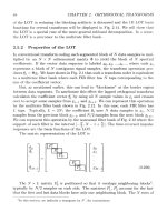
2.1, we illustrate a Project Milestone Schedule for a turnkey power plant. If you
look at Figure 2.1b, you will note that the first level of the schedule is based on
project phases, and that these phases have been overlapped to reduce the overall
project duration to 24 months. The first cut of this schedule, without overlapping,
produced a project duration of 36 months.
USING PROJECT LIFE CYCLES 71
Trap A frequent mistake by novice project managers is to as-
sume that the WBS has to be time oriented. This is not a re-
quirement. In fact, it is preferable to ignore the element of
time when developing a WBS that is based on deliverables, or-
ganization structure, cost accounts, locations, and so on. The
exception is the WBS that is based on the project life cycle. This
one is time oriented—at least at the phase level.
But as a guide (with the above-noted exception), avoid de-
veloping a WBS that looks at items as they occur chronologi-
cally. That’s what the critical path network is for.
See Chapters 2.1 and 2.2 for more on using WBS.
72 PROJECT LIFE CYCLES
SECTION 3
SCHEDULING
T
o many people, project management is synonymous with scheduling. We
know that project management is so much more than that. Nevertheless, it
is scheduling that provides us with the foundation for many of the important
functions that are part of the project management process. Without the defini-
tion of the workscope, and the scheduling of the work, we would not have a ba-
sis for planning the assignment of resources or for managing the cash flow.
Furthermore, the timing of the work and the management of the project
end date are two of the most watched and sensitive areas of most projects.
So, without falling into a false sense that the schedule is everything, we must
recognize that scheduling is a very critical component of the project manage-
ment process.
In Section 2, we discuss the importance of defining and organizing the
workscope, and the value of developing a Project Milestone Schedule. These are
the initial steps toward the development of a detailed project schedule. It is cer-
tainly possible to develop the schedule without the use of the computer. But this
would be folly. First of all, in the manual approach, every time that you made a
change, you would have to redraft the schedule. Of course, you could use simple
bar chart software to generate a manually calculated schedule. This avoids the
complete redrafting of the schedule to incorporate changes. But it would not pro-
vide the benefits of task relationship planning—a key component of the critical
path method (CPM).
With the use of CPM software, you can define the tasks, their durations, and
their relationships and have the program generate a schedule. It is possible to im-
pose your will on what the computer does, by defining constrained start dates,
target end dates, interim milestones, concurrent work, and so forth. You can test
for options and alternatives (what-ifs). You can use the work breakdown structure
and other coding to select, sort, and summarize the schedule data. I could go on
and on about how useful, even necessary, critical path software is. In the chapters
73
that comprise this section, we discuss these benefits and talk about practical ways
to use such tools.
It is unfortunate that many people wait until there is a project crisis before
getting friendly with CPM tools. Then, under the pressure of the crisis, they fail
to learn the few fundamentals that are necessary to utilize these tools effectively.
Frankly, the initial use of these tools can be intimidating. The trick is to get in-
troduced to them when not under extreme pressure, and to take the time to
learn some of the basics. Another good idea is to have a resident CPM guru on
the staff to mentor the others. Last, try to get into the use of CPM progressively,
starting with a small project and with basic functions, and growing in both scope
and functionality.
For every science (project management is both an art and a science) there is a
set of fundamentals. These include basic assumptions, algorithms, formulae,
terms, and protocols. The science of critical path scheduling is not exempt from
this. Therefore, on the possibility that a few readers will not be well versed in
these fundamentals, we have provided a CPM primer, in Chapter 3.1.
In the past decade, a variation of critical path scheduling, called critical chain
project management (CCPM), has emerged as an alternative method to CPM.
We choose not to take a position on this somewhat controversial subject, opting
instead to present a balanced, objective discussion on CCPM vs. CPM, in Chap-
ter 3.2. A major aspect of the CCPM approach is that of shared contingency. This
is a concept that we can strongly support, and we illustrate several ways of achiev-
ing this objective.
We also present a very strong case for the importance of schedules and time
compression, regardless of whether CPM or CCPM is used. Please read Chapter
3.4, to find clear evidence of the multitude of cost penalties due to projects
stretching out longer than planned or necessary.
Schedules are built by defining tasks, estimating task durations, and defining
task relationships. The hardest part is dealing with task durations. For most tasks,
you could come up with a range of times that could be all over the place, and have
no trouble justifying any of them. In Chapter 3.3, we provide a rationale for vari-
ous approaches to estimating durations, and offer some guidance on assigning du-
rations to tasks.
In keeping with the intent of this book to provide guidance for Practical Proj-
ect Management (PPM), Chapter 3.5 offers several pages of tips on how to apply
the basic tools of computer-based scheduling. Nothing fancy, but lots of very ef-
fective suggestions. These tips will help you to develop realistic schedules that re-
flect how you intend to do the job. You’ll find that it is easier than you thought.
Again, this is an important section. The most visible component of the project
plan is the schedule. The schedule is the basis for all the other aspects of the plan,
74 SCHEDULING
including the resource loading plan and the budget. The schedule is also the basis
for progress and performance measurement. Obviously, with a poorly developed
schedule, it will be impossible for any other aspects of the plan to be very useful,
and project control is equally encumbered.
Bad schedules are, unfortunately, fairly common. And the effects of bad
schedules on project performance are terribly harmful. Poor schedules lead to
confusion and inefficient assignment of resources. The project team looks to
the schedule for guidance and gets discouraged when they cannot rely on that
document. Eventually, alternate versions of the schedule appear from sources
that are not satisfied with the official schedule, leading to even more confusion
and desertion.
The development of a valid schedule is not that difficult. It takes some knowl-
edge of scheduling conventions, and some patience to do it right the first time. All
too often, we rush to get that first schedule out, eventually wasting way more time
trying to fix the poor schedule later. We can’t help you with having patience, but
we can do something about the knowledge part. We do that with the next five
chapters, on project scheduling.
SCHEDULING 75
CHAPTER 3.1
CRITICAL PATH SCHEDULING
76
N
ow here’s a boring subject: Critical Path Scheduling! Many of you will be
well-versed in the subject and can move on to more interesting topics. You
can also find detailed discussion on critical path scheduling in many of the basic
books on project management and in books and electronic notes distributed with
all project management software products. For the PM 101 crowd, we include a
brief discussion of critical path scheduling in this chapter.
The Critical Path Method (CPM) is the basis of almost any project schedule.
Even if you do not use a computer for scheduling, you probably use CPM con-
cepts—possibly without even realizing it. My advice is to obtain a good project
management software system and to use the critical path scheduling capabili-
ties effectively to develop and manage your project schedules. Therefore, our
discussion on project scheduling will assume that you are utilizing computers
for planning and control, and that you have critical path scheduling capabilities
on these computers.
What is critical path scheduling? Basically, it is the process of determining
when work can be done, by identifying the precedence relationships between the
tasks. It seems simple enough. Yet, many people botch up this simple process and
several totally ignore the critical path scheduling capabilities, even when using
critical path scheduling tools. What a shame!
CPM Basics
Regardless of the method used to create a project schedule, the first step is al-
ways the same. You must identify the work to be scheduled before you can deter-
mine when the work will be done. There are many ways that you can work up to
the point of developing the schedule. We recommended a few effective practices
in Chapter 2.1, Project Initiation Techniques. We will assume that you will utilize
these practices as we move to the next steps of developing the project schedule.
Reviewing these front-end steps:
• You will have identified the project objectives and constraints.
• You will have initiated strategic planning and performed a stakeholder
analysis.
• You will have developed a set of frameworks for the workscope and timing.
• You’ll use the WBS as a framework for identification of the project tasks.
• You’ll use the Project Milestone Schedule as a framework to develop the de-
tailed project schedule.
The next steps include:
• Creating a list of all the tasks to be performed.
• Estimating the probable duration of each task.
• Defining the precedence relationships between tasks.
• Identifying date constraints and imposed dates.
Let’s look at each of these in greater detail.
Defining Tasks A favored way of building the list of tasks is to use a work
breakdown structure that is based on either deliverables or phases. Actually,
where it is practical, I like to use a combined WBS, where the first level repre-
sents the phases (or project life cycle) and the next level represents the deliver-
ables within each phase. The WBS is then developed down to lower levels, such
as major components, subsets, or milestones within each deliverable, and then
further, down to groups of tasks that I like to call work packages. A work pack-
age is a set of tasks, usually under the responsibility of a single party, that repre-
sents a minor deliverable or milestone. Each task will have a single party
identified as the responsible owner. Tasks may have one or more resources as-
signed and may have budgets (later). Every task (like every project) has an iden-
tifiable start and finish.
CPM BASICS 77
Estimating Task Durations There are several ways to assign a duration to each
task. The most common is to just come up with an estimated time and establish
that as the task duration. Depending on the type of work, these durations may be
in days, weeks, hours, and so on. In each case, these are considered elapsed times.
For example, a task that has been assigned a 10-day duration is expected to take 2
weeks (assuming a 5-day-a-week calendar). It does not necessarily mean that the
task is worked on for all of these 10 days, or that it is a 10 man-day effort. Later, in
our discussion of schedule risk, we introduce the concept of multiple duration es-
timates. But we’ll leave these alone for now.
A second popular method of determining task durations is called effort-driven.
With this method, we enter the total hours to be applied by each resource that is
working on the task, as well as specifying the rate of effort. For example, a wall is
built by two bricklayers, working full time, for a total of 80 hours. The task dura-
tion is calculated as 5 days (40 elapsed hours). If there are multiple resources and
rates of effort, the task duration is determined by the longest assignment.
There are numerous variations and fine points that can be introduced here,
but we proceed with our coverage of critical path scheduling using these two clas-
sic methods.
Task Precedence Relationships and Date Constraints Scheduling, of course, is
deciding when the work will be performed. In a few instances, this timing will be
free of constraints. But this is the exception to the rule. It is more likely that the
timing of the work will be influenced by one or more factors. These may include:
• A date committed by contract or other agreement.
• Dependencies on other tasks.
• Availability of required conditions (weather, space, permits, funding, etc.).
• Availability of materials.
• Availability of labor resources.
The critical path method allows the specification of any and all of these con-
straining and dependency conditions. The normal process calls for the identifica-
tion of task dependencies, followed by the imposition of dates that will force the
calculated timing to be overridden. Let’s examine these options in greater detail.
Defining Dependencies The default dependency is a Finish to Start (FS) rela-
tionship. That is, task B cannot start until task A is finished. However, conditions
may exist where an overlap is possible. For instance, task B can start 2 days after
task A starts. This is designated as a Start to Start (SS) relationship. There can also
be instances where 2 tasks can start independently of each other, but the comple-
78 CRITICAL PATH SCHEDULING
tion of one is dependent upon the completion of another. Here, you would use
the Finish to Finish (FF) relationship. For instance, task B can finish 5 days after
the completion of task A (FF-5). The duration of the delay (in this case, 5 days) is
called the lag.
Tip A practical way of working with critical path scheduling
is to start off by defining most relationships as default FS de-
pendencies. Then, after the project schedule has been calcu-
lated, use the ability to overlap tasks to selectively compact
the project duration. See Chapter 3.4 for discussion on the
value of time compression and Chapter 3.5 for more tips on
practical scheduling.
CPM: How It Works There are several options for imposing date constraints on
the schedule. In order to understand how these work, we have to pause a moment
to review how critical path scheduling works.
After the project model has been defined to the computer (task definition, task
durations, dependencies, and imposed date constraints), the computer makes a
forward pass to determine the earliest start and finish of all tasks. Then, after de-
termining the earliest project completion date, the computer makes a backward
pass from that end date, to calculate the latest start and finish date of all tasks that
would support the project end date.
The difference between the early dates and the late dates is called total float or
total slack. The path through the critical path network that has the least amount
of float or slack is called the critical path. If the user has not imposed a required
end date on the project, the critical path would have a float/slack of zero. If a proj-
ect end date is imposed that is earlier than the freely computed end date, there
will be tasks that have negative float. The tasks having the largest amount of nega-
tive float are said to lie on the critical path.
Therefore, it can be noted that any tasks that lie on the critical path cannot be
delayed without delaying the completion of the project.
Tip The terms float and slack are used interchangeably. They
are the same. Float had been the common usage, until Mi-
crosoft introduced their scheduling products, which substi-
tuted slack for float.
CPM BASICS 79
The forward pass establishes a pair of early dates for each task. These are
called Early Start and Early Finish. The backward pass establishes a pair of late
dates. These are called the Late Start and Late Finish. The difference between
the early dates and the late dates is the total float.
Tool Tip Sometimes the user does not wish to publish the late
dates or the float. This is controlled in the reporting process. In
such situations, it is also popular to change the name of the
early dates to something like Scheduled Start and Scheduled
Finish, or perhaps just Start and Finish. Just about all programs
allow the user to rename the standard calculated fields.
Also, at times, the user does not wish to calculate or publish
the early dates. Instead they want to have the dates calculated
and displayed as the latest dates. This would be equivalent to a
just-in-time scheduling approach. Most products have an ALAP
(as late as possible) calculation option that can be used to ac-
complish this. The default is the ASAP (as soon as possible) mode.
Date Constraints Now that we understand how the CPM calculates schedule
dates, we can understand how to use imposed dates and how they affect the
schedule calculations. Of the several options to impose dates, the most popular of
these is the Start No Earlier Than (SNET) or Finish No Later Than (FNLT).
The SNET dates are used to impose a task start date that may be later than the
earliest start as determined by the computer. They may override the forward pass
calculations. For example, the computer may determine that a ditch can be exca-
vated starting on January 15 (based on completion of identified predecessors). How-
ever, your crew may not want to initiate any excavation work (in Montana) prior to
March 15, due to the frigid weather. By imposing a SNET date of 3/15, the calcu-
lated early start of 1/15 is overridden. Note that if, for any reason, the predecessors
slip out beyond the 3/15 date, the imposed date is now overridden by the naturally
calculated date. This is why we call such an imposed date Start No Earlier Than,
rather than Start On, which is a forced date that is not overridden by the calculations.
Trap First time users of project management software often
tend to overuse imposed dates, especially the Start On option.
In an attempt to force the schedule to predetermined dates,
this improper use of the Start On option creates two problems.
80 CRITICAL PATH SCHEDULING
TEAMFLY
Team-Fly
®
First, it prevents determination of a schedule that is based on
defined dependencies. Second, it makes updating the sched-
ule much more difficult, as the user must go in and manually
change all of the imposed dates.
Often, this overuse of imposed Start On dates is motivated
by a desire to avoid the effort of defining all the dependen-
cies. Ironically, the result is not only a poorly developed sched-
ule, but also vastly increased effort to maintain it.
Furthermore, one of the great benefits of project manage-
ment software comes from using these tools to help develop a
supportable schedule, based on defined work, dependencies,
and available resources. Ignoring all of this to create a forced
schedule may be easier to do and more politically acceptable.
But if it is not supported by the facts, what good is it in the
long run?
The Finish No Later Than (FNLT) constraint works in just the opposite man-
ner from the SNET constraint. The FNLT date, when imposed, affects the calcu-
lation of the late dates. This can be best illustrated by an example. Let’s say that
the calculated schedule for construction of a house says that the roof can be com-
pleted as late as March 15 in order to meet the contract house completion date of
June 30. We are in Iowa and the snow can be expected to make a substantial ap-
pearance by December 1. It is decided that it is important to have the roof up by
that date in order to be able to work inside the house and to protect the materials.
By imposing a FNLT date of 12/1 on the roof completion task, we then drive all
other late dates to support that imposed constraint. The FNTL date does not
have any effect on the early dates, which are computed during the forward pass.
Other Constraints Some of the constraints on scheduling the work of the proj-
ect may involve events and conditions that are not on the list of defined tasks. We
may be waiting for the availability of the plot on which to erect the house. Or we
need the building permit. Erection of the roof trusses may require the availability
of a crane. Purchasing of the erection materials may be dependent upon the avail-
ability of funds. Placement of the windows may be constrained by completion and
approval of the final construction drawings. Availability of the electricians may
depend on completion of the electrical work on another building.
Actually, all of these constraints should be incorporated into the project
schedule. For most of those in the preceding list, we would create a new task
(which may have a zero duration) to note the constraint. We would enter a
CPM BASICS 81
SNET date on these “dummy” tasks and make them predecessors to the tasks
that cannot be started until this constraint is satisfied. For instance, you may be
able to survey and lay out the lot while waiting for the building permit. But the
first excavation task would be constrained by a starter task called Obtain Build-
ing Permit. The duration would be zero. A SNET date would be imposed based
on the expected permit date. This task would be defined as a Finish to Start
predecessor to the excavation task. A zero-time task is often called an event, be-
cause it is a point in time.
Tip Creating dummy tasks to note any of the above con-
straints is favorable over just imposing a SNET date on the af-
fected task. There are two reasons for this. First, by using a
distinct task, there is a specific, separate line item in which we
can define the specific constraint. Second, there could be more
than one such constraint for a task. We can use a separate con-
straint task for each.
Still More Constraints Up to this point, we have allowed the schedule to be
computed without considering the availability of labor resources. We have as-
sumed that whatever resources are needed to support the work, when scheduled,
would be available. Obviously, this is not a good assumption. Eventually, we will
want to build a definition of available resources and to allow the program to con-
sider the availability of resources while making an adjusted computation of the
schedule. This is called Resource Leveling, or Resource-Constrained Scheduling,
and will be discussed in detail in Section 4.
If we have defined the resources needed to perform the tasks, we can have the
CPM program calculate the quantity of each resource required for each date.
These quantities may be number of units of a resource (when using classes of re-
sources, such as electricians) or may be number of hours per time period for
named resources, such as Jack Smith, a systems designer. By executing this calcu-
lation of required resource quantities, we can see and evaluate the level of re-
sources needed to support the schedule (prior to adjusting for resource limits).
This process, of computing the required resources against time, is sometimes
called Resource Aggregation.
Where the resource aggregation indicates that there is a significant period of
time where resource needs will peak, you can use this as an early warning to ei-
ther try to arrange for added resources, or to be prepared for significant schedule
adjustments. More on this in Section 4.
82 CRITICAL PATH SCHEDULING
Baselines Do not expect to have an acceptable schedule after the first computa-
tion. Even without adjusting for resources, it is likely that there will have to be
several iterations before the computed schedule satisfies the stakeholders and the
key dates in the Project Milestone Schedule.
Once an acceptable schedule has been developed, it is customary to save the
set of dates as a Baseline Schedule. This baseline represents a set of targets that
will be used to compare progress as the work moves forward. Each task will gain a
new pair of dates, usually called Baseline Start and Baseline Finish. Target Start
and Finish are alternate headings.
Trick It is often desirable to be able to save multiple base-
lines. The first is usually the initial or contract baseline. A sec-
ond might be a set of negotiated revision dates. I usually
reserve one baseline set for my last schedule computation.
Then I can compare the next update to that baseline to ana-
lyze changes during the last period.
This completes our overview of critical path scheduling. We can go into con-
siderably more detail, but this might add to the confusion. At this time, you know
enough to be able to appreciate some of the issues associated with project sched-
uling, such as discussed in Chapters 3.2 (Critical Path, Critical Chain, and Uncer-
tainty) and 3.4 (How Important Are Schedules and Time Compression?). In
Chapter 3.5, Practical Scheduling, we look at ways to use these basic scheduling
capabilities in a practical and effective manner.
CPM BASICS 83
CHAPTER 3.2
CRITICAL PATH, CRITICAL
CHAIN, AND UNCERTAINTY
Exploring Concepts of Shared Contingency
84
I
n the 45 years that formal critical path scheduling has been around, all the pop-
ular protocols essentially dealt with uncertainty in a similar way. They addressed
it (if at all) on a task by task basis. The original PERT method did have a formal
mechanism for uncertainty, by providing for three task durations (optimistic, most
likely, and pessimistic). Some of today’s CPM programs have carried over this
three-duration capability (see Chapter 6.3). For those that did not employ the
three-duration approach, uncertainty was dealt with by sneaking in a bit of extra
time in each task duration estimate.
There are several problems with this approach. In the case of the latter, hap-
hazard approach, there was no consistency in the treatment of the schedule con-
tingency allowance, and there was no documentation of what part of the duration
was actual contingency. In all the approaches, the contingency (allowance for un-
certainty) was doled out to each individual task, although the actual uncertainty
would be better addressed on a group of tasks basis.
This situation has been explored by several individuals, and there is a growing
interest in some emerging treatment of (what I call) shared contingency.
Trap Schedule contingency is a vital component of a success-
ful project. However, this contingency must be clearly identi-
fied and managed. Inconsistent and unstructured padding of