emerging wireless multimedia services and technologies phần 3 ppt
Bạn đang xem bản rút gọn của tài liệu. Xem và tải ngay bản đầy đủ của tài liệu tại đây (638.51 KB, 46 trang )
3.8 RTP Payload Types
As already mentioned, RTP is a protocol framework that allows the support of new encodings and
features. Each particular RTP/RTCP-based application is accompanied by one or more documents:
a profile specification document, which defines a set of payload type codes and their mapping to
payload formats (e.g., media encodings) – a profile for audio and video data may be found in the
companion RFC3551 [27];
payload format specification documents, which define how a particular payload, such as an audio or
video encoding, is to be carried in RTP.
3.8.1 RTP Profiles for Audio and Video Conferences (RFC3551)
RFC3551 lists a set of audio and video encodings used within audio and video conferences with
minimal, or no session control. Each audio and video encoding comprises:
a particular media data compression or representation called payload type, plus
a payload format for encapsulation within RTP.
RFC3551 reserves payload type numbers in the ranges 1–95 and 96–127 for static and dynamic
assignment, respectively. The set of static payload type (PT) assignments is provided in Tables 3.7 and
3.8 (see column PT).
Payload type 13 indicates the Comfort Noise (CN) payload format specified in RFC 3389.
Some of the payload formats of the payload types are specified in RFC3551, while others are speci-
fied in separate RFCs. RFC3551 also assigns to each encoding a short name (see column short encoding
name) which may be used by higher-level control protocols, such as the Session Description Protocol
(SDP), RFC 2327 [25], to identify encodings selected for a particular RTP session.
Mechanisms for defining dynamic payload type bindings have been specified in the Session Descrip-
tion Protocol (SDP) and in other protocols, such as ITU-T Recommendation H.323/H.245. These
mechanisms associate the registered name of the encoding/payload format, along with any additional
required parameters, such as the RTP timestamp clock rate and number of channels, with a payload
type number. This association is effective only for the duration of the RTP session in which the
dynamic payload type binding is made. This association applies only to the RTP session for which it is
made, thus the numbers can be reused for different encodings in different sessions so the number space
limitation is avoided.
3.8.1.1 Audio
RTP Clock Rate
The RTP clock rate used for generating the RTP timestamp is independent of the number of channels
and the encoding; it usually equals the number of sampling periods per second. For N-channel
encodings, each sampling period (say, 1/8000 of a second) generates N samples. If multiple audio
channels are used, channels are numbered left-to-right, starting at one. In RTP audio packets,
information from lower-numbered channels precedes that from higher-numbered channels.
Samples for all channels belonging to a single sampling instant must be within the same packet. The
interleaving of samples from different channels depends on the encoding. The sampling frequency
is drawn from the set: 8000, 11 025, 16 000, 22 050, 24 000, 32 000, 44 100 and 48 000 Hz. However,
most audio encodings are defined for a more restricted set of sampling frequencies.
For packetized audio, the default packetization interval has a duration of 20 ms or one frame, which-
ever is longer, unless otherwise noted in Table 3.7 (column Default ‘ms/packet’). The packetization
interval determines the minimum end-to-end delay; longer packets introduce less header overhead
72 Multimedia Transport Protocols for Wireless Networks
Table 3.7 Payload types (PT) and properties for audio encodings (n/a: not applicable)
Short encoding Sample or Sampling (clock) Default
PT name frame Bits/sample rate (Hz) ms/ frame ms/ packet Channels
0 PCMU Sample 8 var. 20 1
1 Reserved
2 Reserved
3 GSM Frame n/a 8000 20 20 1
4 G723 Frame n/a 8000 30 30 1
5 DVI4 Sample 4 8000 20 1
6 DVI4 Sample 4 16 000 20 1
7 LPC Frame n/a 8000 20 20 1
8 PCMA Sample 8 8000 20 1
9 G722 Sample 8 16 000 20 1
10 L16 Sample 16 44 100 20 2
11 L16 Sample 16 44 100 20 1
12 QCELP Frame n/a 8000 20 20 1
13 CN 8000 1
14 MPA Frame n/a 90 000 var.
15 G728 Frame n/a 8000 2.5 20 1
16 DVI4 Sample 4 11 025 20 1
17 DVI4 Sample 4 22 050 20 1
18 G729 Frame na 8000 10 20 1
19 Reserved
20 Unassigned
21 Unassigned
22 Unassigned
23 Unassigned
dyn G726-40 Sample 5 8000 20 1
dyn G726-32 Sample 4 8000 20 1
dyn G726-24 Sample 3 8000 20 1
dyn G726-16 Sample 2 8000 20 1
dyn G729D Frame n/a 8000 10 20 1
dyn G729E Frame n/a 8000 10 20 1
dyn GSM-EFR Frame n/a 8000 20 20 1
dyn L8 Sample 8 Variable 20 Variable
dyn RED
dyn VDVI Sample Variable Variable 20 1
Table 3.8 Payload types (PT) for video and combined encodings
PT Short encoding name Clock rate (Hz) PT Short encoding name Clock rate (Hz)
24 Unassigned 32 MPV 90 000
25 CelB 90 000 33 MP2T 90 000
26 JPEG 90 000 34 H263 90 000
27 Unassigned 35–71 Unassigned
28 nv 90 000 72–76 Reserved
29 Unassigned 77–95 Unsigned
30 Unassigned 96–127 Dynamic
31 H261 90 000 Dyn h263-1998 90 000
RTP Payload Types 73
but higher delay and make packet loss more noticeable. For non-interactive applications such as lectures
or for links with severe bandwidth constraints, a higher packetization delay may be used. A receiver
should accept packets representing between 0 and 200 ms of audio data. This restriction allows reason-
able buffer sizing for the receiver.
Sample and Frame-based Encodings
In sample-based encodings, each audio sample is represented by a fixed number of bits. An RTP audio
packet may contain any number of audio samples, subject to the constraint that the number of bits per
sample times the number of samples per packet yields an integral octet count.
The duration of an audio packet is determined by the number of samples in the packet. For sample-
based encodings producing one or more octets per sample; samples from different channels sampled
at the same sampling instant are packed in consecutive octets. For example, for a two-channel encoding,
the octet sequence is (left channel, first sample), (right channel, first sample), (left channel, second
sample), (right channel, second sample) The packing of sample-based encodings producing less
than one octet per sample is encoding-specific.
The RTP timestamp reflects the instant at which the first sample in the packet was sampled, that is,
the oldest information in the packet.
Frame-based encodings encode a fixed-length block of audio into another block of compressed data,
typically also of fixed length. For frame-based encodings, the sender may choose to combine several
such frames into a single RTP packet. The receiver can tell the number of frames contained in an RTP
packet, provided that all the frames have the same length, by dividing the RTP payload length by the
audio frame size that is defined as part of the encoding.
For frame-based codecs, the channel order is defined for the whole block. That is, for two-channel
audio, right and left samples are coded independently, with the encoded frame for the left channel
preceding that for the right channel.
All frame-oriented audio codecs are able to encode and decode several consecutive frames within
a single packet. Since the frame size for the frame-oriented codecs is given, there is no need to use a
separate designation for the same encoding, but with different number of frames per packet.
RTP packets contain a number of frames which are inserted according to their age, so that the oldest
frame (to be played first) is inserted immediately after the RTP packet header. The RTP timestamp
reflects the instant at which the first sample in the first frame was sampled, that is, the oldest information
in the packet.
Silence Suppression
Since the ability to suppress silence is one of the primary motivations for using packets to transmit
voice, the RTP header carries both a sequence number and a timestamp to allow a receiver to distinguish
between lost packets and periods of time when no data are transmitted. Discontinuous transmission
(silence suppression) is used with any audio payload format. In the sequel, the audio encodings are listed:
DVI4: DVI4 uses an adaptive delta pulse code modulation (ADPCM) encoding scheme that was
specified by the Interactive Multimedia Association (IMA) as the ‘IMA ADPCM wave type’.
However, the encoding defined in RFC3551 here as DVI4 differs in three respects from the IMA
specification.
G722: G722 is specified in ITU-T Recommendation G.722, ‘7 kHz audio-coding within 64 kbit/s’.
The G.722 encoder produces a stream of octets, each of which shall be octet-aligned in an RTP packet.
G723: G723 is specified in ITU Recommendation G.723.1, ‘Dual-rate speech coder for multimedia
communications transmitting at 5.3 and 6.3 kbit/s’. The G.723.1 5.3/6.3 kbit/s codec was defined by
the ITU-T as a mandatory codec for ITU-T H.324 GSTN videophone terminal applications.
G726-40, G726-32, G726-24 and G726-16: ITU-T Recommendation G.726 describes, among others,
the algorithm recommended for conversion of a single 64 kbit/s A-law or mu-law PCM channel
encoded at 8000 samples/sec to and from a 40, 32, 24, or 16 kbit/s channel.
74 Multimedia Transport Protocols for Wireless Networks
G729: G729 is specified in ITU-T Recommendation G.729, ‘Coding of speech at 8 kbit/s using
conjugate structure-algebraic code excited linear prediction (CS-ACELP)’.
GSM: GSM (Group Speciale Mobile) denotes the European GSM 06.10 standard for full-rate speech
transcoding, ETS 300 961, which is based on RPE/LTP (residual pulse excitation/long term predic-
tion) coding at a rate of 13 kbit/s.
GSM-EFR: GSM-EFR denotes GSM 06.60 enhanced full rate speech transcoding, specified in ETS
300 726.
L8: L8 denotes linear audio data samples, using 8 bits of precision with an offset of 128, that is, the
most negative signal is encoded as zero.
L16: L16 denotes uncompressed audio data samples, using 16-bit signed representation with 65 535
equally divided steps between minimum and maximum signal level, ranging from À32 768 to 32 767.
LPC: LPC designates an experimental linear predictive encoding.
MPA: MPA denotes MPEG-1 or MPEG-2 audio encapsulated as elementary streams. The encoding is
defined in ISO standards ISO/IEC 11172-3 and 13818-3. The encapsulation is specified in RFC 2250.
PCMA and PCMU: PCMA and PCMU are specified in ITU-T Recommendation G.711. Audio data is
encoded as eight bits per sample, after logarithmic scaling. PCMU denotes mu-law scaling, PCMA
A-law scaling.
QCELP: The Electronic Industries Association (EIA) and Telecommunications Industry Association
(TIA) standard IS-733, ‘TR45: High Rate Speech Service Option for Wideband Spread Spectrum
Communications Systems’, defines the QCELP audio compression algorithm for use in wireless
CDMA applications.
RED: The redundant audio payload format ‘RED’ is specified by RFC 2198. It defines a means by
which multiple redundant copies of an audio packet may be transmitted in a single RTP stream.
VDVI: VDVI is a variable-rate version of DVI4, yielding speech bit rates between 10 and 25 kbit/s.
3.8.1.2 Video
This section describes the video encodings that are defined in RFC3551 and give their abbreviated
names used for identification. These video encodings and their payload types are listed in Table 3.8. All
of these video encodings use an RTP timestamp frequency of 90 000 Hz, the same as the MPEG
presentation time stamp frequency. This frequency yields exact integer timestamp increments for the
typical 24 (HDTV), 25 (PAL), and 29.97 (NTSC) and 30 (HDTV) Hz frame rates and 50, 59.94 and
60 Hz field rates. While 90 Hz is the recommended rate for future video encodings used within this
profile, other rates may be used as well. However, it is not sufficient to use the video frame rate
(typically between 15 and 30 Hz) because that does not provide adequate resolution for typical
synchronization requirements when calculating the RTP timestamp corresponding to the NTP time-
stamp in an RTCP SR packet. The timestamp resolution must also be sufficient for the jitter estimate
contained in the receiver reports.
For most of these video encodings, the RTP timestamp encodes the sampling instant of the video
image contained in the RTP data packet. If a video image occupies more than one packet, the timestamp
is the same on all of those packets. Packets from different video images are distinguished by their
different timestamps.
Most of these video encodings also specify that the marker bit of the RTP header is set to one in the
last packet of a video frame and otherwise set to zero. Thus, it is not necessary to wait for a following
packet with a different timestamp to detect that a new frame should be displayed. In the sequel, the
video encodings are listed:
CelB: The CELL-B encoding is a proprietary encoding proposed by Sun Microsystems. The byte
stream format is described in RFC 2029.
JPEG: The encoding is specified in ISO Standards 10918-1 and 10918-2. The RTP payload format
is as specified in RFC 2435.
RTP Payload Types 75
Table 3.9 RFC for RTP profiles and payload format
Protocols and payload formats
RFC 1889 RTP: A transport protocol for real-time applications (obsoleted by RFC 3550)
RFC 1890 RTP profile for audio and video conferences with minimal control (obsoleted by RFC 3551)
RFC 2035 RTP payload format for JPEG-compressed video (obsoleted by RFC 2435)
RFC 2032 RTP payload format for H.261 video streams
RFC 2038 RTP payload format for MPEG1/MPEG2 video obsoleted by RFC 2250
RFC 2029 RTP payload format of Sun’s CellB video encoding
RFC 2190 RTP payload format for H.263 video streams
RFC 2198 RTP payload for redundant audio data
RFC 2250 RTP payload format for MPEG1/MPEG2 video
RFC 2343 RTP payload format for bundled MPEG
RFC 2429 RTP payload format for the 1998 version of ITU-T Rec. H.263 Video (H.263þ)
RFC 2431 RTP payload format for BT.656 video encoding
RFC 2435 RTP payload format for JPEG-compressed video
RFC 2733 An RTP payload format for generic forward error correction
RFC 2736 Guidelines for writers of RTP payload format specifications
RFC 2793 RTP payload for text conversation
RFC 2833 RTP payload for DTMF digits, telephony tones and telephony signals
RFC 2862 RTP payload format for real-time pointers
RFC 3016 RTP payload format for MPEG-4 audio/visual streams
RFC 3047 RTP payload format for ITU-T Recommendation G.722.1
RFC 3119 A more loss-tolerant RTP payload format for MP3 audio
RFC 3158 RTP testing strategies
RFC 3189 RTP payload format for DV format video
RFC 3190 RTP payload format for 12-bit DAT, 20- and 24-bit linear sampled audio
RFC 3267 RTP payload format and file storage format for the Adaptive Multi-Rate (AMR) and Adaptive
Multi-Rate Wideband (AMR-WB) audio codecs
RFC 3389 RTP payload for comfort noise
RFC 3497 RTP payload format for Society of Motion Picture and Television Engineers (SMPTE) 292M
video
RFC 3550 RTP: A transport protocol for real-time applications
RFC 3551 RTP profile for audio and video conferences with minimal control
RFC 3555 MIME type registration of RTP payload formats
RFC 3557 RTP payload format for European Telecommunications Standards Institute (ETSI) European
Standard ES 201 108 distributed speech recognition encoding
RFC 3558 RTP payload format for Enhanced Variable Rate Codecs (EVRC) and Selectable Mode Vocoders
(SMV)
RFC 3640 RTP payload format for transport of MPEG-4 elementary streams
RFC 3711 The secure real-time transport protocol
RFC 3545 Enhanced compressed RTP (CRTP) for links with high delay, packet loss and reordering
RFC 3611 RTP Control Protocol Extended Reports (RTCP XR)
Repairing losses
RFC 2354 Options for repair of streaming media
Others
RFC 3009 Registration of parity FEC MIME types
RFC 3556 Session Description Protocol (SDP) bandwidth modifiers for RTP Control Protocol (RTCP)
bandwidth
RFC 2959 Real-time transport protocol management information base
RFC 2508 Compressing IP/UDP/RTP headers for low-speed serial links
RFC 2762 Sampling of the group membership in RTP
76 Multimedia Transport Protocols for Wireless Networks
H261: The encoding is specified in ITU-T Recommendation H.261, ‘Video codec for audiovisual
services at p  64 Kbit/s’. The packetization and RTP-specific properties are described in RFC 2032.
H263: The encoding is specified in the 1996 version of ITU-T Recommendation H.263, ‘Video
coding for low bit rate communication’. The packetization and RTP-specific properties are described
in RFC 2190.
H263-1998: The encoding is specified in the 1998 version of ITU-T Recommendation H.263, ‘Video
coding for low bit rate communication’. The packetization and RTP-specific properties are described
in RFC 2429.
MPV: MPV designates the use of MPEG-1 and MPEG-2 video encoding elementary streams as
specified in ISO Standards ISO/IEC 11172 and 13818-2, respectively. The RTP payload format is
as specified in RFC 2250. The MIME registration for MPV in RFC 3555 specifies a parameter that
may be used with MIME or SDP to restrict the selection of the type of MPEG video.
MP2T: MP2T designates the use of MPEG-2 transport streams, for either audio or video. The RTP
payload format is described in RFC 2250.
nv: The encoding is implemented in the program ‘nv’, version 4, developed at Xerox PARC.
Table 3.9 summarizes the RFCs defined for RTP profiles and payload format.
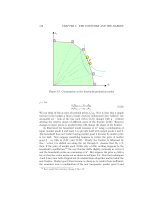
3.9 RTP in 3G
This section summarizes the supported media types in 3G and RTP implementation issues for 3G,
as reported in 3GPP TR 26.937 [2], TR 26.234 [33] and TR 22.233 [34].
Figure 3.10 shows the basic entities involved in a 3G Packet-Switch Streaming Service (PSS).
Clients initiate the service and connect to the selected Content Server. Content Servers, apart from
prerecorded content, can generate live content, e.g. video, from a concert or TV (see Table 3.10:
Potential services over PSS.). User Profile and terminal capability data can be stored in a network
server and will be accessed at the initial set up. User Profile will provide the PSS service with the
user’s preferences. Terminal capabilities will be used by the PSS service to decide whether or not
Streaming
Client
Content
Servers
User and
terminal
profiles
Portals
IP Network
Content
Cache
3GPP
Core Network
UTRAN
GERAN
SGSN GGSN
Streaming
Client
Figure 3.10 Network elements involved in a 3G packet switched streaming service.
RTP in 3G 77
the client is capable of receiving the streamed content. Portals are servers allowing for a convenient
access to streamed media content. For instance, a portal might offer content browse and search facilities.
In the simplest case, it is simply a Web/WAP-page with a list of links to streaming content. The content
itself is usually stored in content servers, which can be located elsewhere in the network.
3.9.1 Supported Media Types in 3GPP
In the 3GPP’s Packet-Switched streaming Service (PSS), the communication between the client and
the streaming servers, including session control and transport of media data, is IP-based. Thus, the RTP/
UDP/IP and HTTP/TCP/IP protocol stacks have been adopted for the transport of continuous media and
discrete media, respectively. The supported continuous media types are restricted to the following set:
AMR narrow-band speech codec RTP payload format according to RFC3267 [28],
AMR-WB (WideBand) speech codec RTP payload format according to RF3267 [28],
MPEG-4 AAC audio codec RTP payload format according to RFC 3016 [29],
MPEG-4 video codec RTP payload format according to RFC 3016 [29],
H.263 video codec RTP payload format according to RFC 2429 [30].
The usage scenarios of the above continuous data are:
(1) voice only streaming (AMR at 12.2 kbps),
(2) high-quality voice/low quality music only streaming (AMR-WB at 23.85 kbps),
(3) music only streaming (AAC at 52 kbps),
(4) voice and video streaming (AMR at 7.95 kbps þ video at 44 kbps),
(5) voice and video streaming (AMR at 4.75 kbps þ video at 30 kbps).
During streaming, the packets are encapsulated using RTP/UDP/IP protocols. The total header overhead
consists of: IP header: 20 bytes for IPv4 (IPv6 would add a 20 bytes overhead); UDP header: 8 bytes;
RTP header: 12 bytes.
Table 3.10 Potential services over PSS
Infotainment
Video on demand, including TV
Audio on demand, including news, music, etc.
Multimedia travel guide
Karaoke – song words change colour to indicate when to sing
Multimedia information services: sports, news, stock quotes, traffic
Weather cams – gives information on other part of country or the world
Edutainment
Distance learning – video stream of teacher or learning material together with teacher’s voice or audio track.
How to ? service – manufacturers show how to program the VCR at home
Corporate
Field engineering information – junior engineer gets access to online manuals to show how to repair, say, the central
heating system
Surveillance of business premises or private property (real-time and non-real-time)
M-commerce
Multimedia cinema ticketing application
On line shopping – product presentations could be streamed to the user and then the user could buy on line.
78 Multimedia Transport Protocols for Wireless Networks
The supported discrete media types (which use the HTTP/TCP/IP stack) for scene description, text,
bitmap graphics and still images, are as follows:
Still images: ISO/IEC JPEG [35] together with JFIF [36] decoders are supported. The support for
ISO/IEC JPEG only apply to the following modes: baseline DCT, non-differential, Huffman coding,
and progressive DCT, non-differential, Huffman coding.
Bitmap graphics: GIF87a [40], GIF89a [41], PNG [42].
Synthetic audio: The Scalable Polyphony MIDI (SP-MIDI) content format defined in Scalable
Polyphony MIDI Specification [45] and the device requirements defined in Scalable Polyphony MIDI
Device 5-to-24 Note Profile for 3GPP [46] are supported. SP-MIDI content is delivered in the struc-
ture specified in Standard MIDI Files 1.0 [47], either in format 0 or format 1.
Vector graphics: The SVG Tiny profile [43, 44] shall be supported. In addition SVG Basic profile
[43, 44] may be supported.
Text: The text decoder is intended to enable formatted text in a SMIL presentation. The UTF-8 [38]
and UCS-2 [37] character coding formats are supported. A PSS client shall support:
text formatted according to XHTML Mobile Profile [32, 48];
rendering a SMIL presentation where text is referenced with the SMIL 2.0 ‘text’ element together
with the SMIL 2.0 ‘src’ attribute.
Scene description: The 3GPP PSS uses a subset of SMIL 2.0 [39] as format of the scene description.
PSS clients and servers with support for scene descriptions support the 3GPP PSS SMIL Language
Profile (defined in 3GPP TS 26.234 specification [33]). This profile is a subset of the SMIL 2.0
Language Profile, but a superset of the SMIL 2.0 Basic Language Profile. It should be noted that
not that all streaming sessions are required to use SMIL. For some types of sessions, e.g. consisting
of one single continuous media or two media synchronized by using RTP timestamps, SMIL may not
be needed.
Presentation description: SDP is used as the format of the presentation description for both PSS
clients and servers. PSS servers shall provide and clients interpret the SDP syntax according to
the SDP specification [25] and appendix C of [24]. The SDP delivered to the PSS client shall declare
the media types to be used in the session using a codec specific MIME media type for each media.
3.9.2 RTP Implementation Issues for 3G
3.9.2.1 Transport and Transmission
Media streams can be packetized using different strategies. For example, video encoded data could be
encapsulated using:
one slice of a target size per RTP packet;
one Group of Blocks (GOB), that is, a row of macroblocks per RTP packet;
one frame per RTP packet.
Speech data could be encapsulated using an arbitrary (but reasonable) number of speech frames per
RTP packet, and using bit- or byte alignment, along with options such as interleaving. The transmission
of RTP packets take place in two different ways:
(1) VBRP (Variable Bit Rate Packet) transmission – the transmission time of a packet depends solely
on the timestamp of the video frame to which the packet belongs, therefore, the video rate variation
is directly reflected to the channel;
(2) CBRP (Constant Bit Rate Packet) transmission – the delay between sending consecutive packets is
continuously adjusted to maintain a near constant rate.
RTP in 3G 79
3.9.2.2 Maximum and Minimum RTP Packet Size
The RFC 3550 (RTP) [26] does not impose a maximum size for RTP packets. However, when RTP
packets are sent over the radio link of a 3GPP PSS, limiting the maximum size of RTP packets can be
advantageous.
Two types of bearers can be envisaged for streaming using either acknowledged mode (AM) or
unacknowledged mode (UM) Radio Link Control (RLC). The AM uses retransmissions over the radio
link, whereas the UM does not. In UM mode, large RTP packets are more susceptible to losses over the
radio link compared with small RTP packets, since the loss of a segment may result in the loss of the
entire packet. On the other hand in AM mode, large RTP packets will result in a larger delay jitter
compared with small packets, as it is more likely that more segments have to be retransmitted.
Fragmentation is one more reason for limiting packet sizes. It is well known that fragmentation
causes:
increased bandwidth requirement, due to additional header(s) overhead;
increased delay, because of operations of segmentation and re-assembly.
Implementers should consider avoiding/preventing fragmentation at any link of the transmission path
from the streaming server to the streaming client.
For the above reasons it is recommended that the maximum size of RTP packets is limited, taking into
account the wireless link. This will decrease the RTP packet loss rate particularly for RLC in UM.
For RLC in AM the delay jitter will be reduced, permitting the client to use a smaller receiving buffer.
It should also be noted that too small RTP packets could result in too much overhead if IP/UDP/RTP
header compression is not applied or unnecessary load at the streaming server. While there are no
theoretical limits for the usage of small packet sizes, implementers must be aware of the implications
of using too small RTP packets. The use of such packets would result in three drawbacks.
(1) The RTP/UDP/IP packet header overhead becomes too large compared with the media data.
(2) The bandwidth requirement for the bearer allocation increases, for a given media bit rate.
(3) The packet rate increases considerably, producing challenging situations for server, network and
mobile client.
As an example, Figure 3.11 shows a chart with the bandwidth partitions between RTP payload media
data and RTP/UDP/IP headers for different RTP payload sizes. The example assumes IPv4. The space
RTP payload vs. headers overhead
0%
10%
20%
30%
40%
50%
60%
70%
80%
90%
100%
14 32 61 100 200 500 750 1000 1250
RTP payload size (bytes)
RTP/UDP/IPv4 headers
RTP payload
Figure 3.11 Bandwidth of RTP payload and RTP/UDP/IP header for different packet sizes.
80 Multimedia Transport Protocols for Wireless Networks
occupied by RTP payload headers is considered to be included in the RTP payload. The smallest
RTP payload sizes (14, 32 and 61 bytes) are examples related to minimum payload sizes for AMR
at 4.75 kbps, 12.20 kbps and for AMR-WB at 23.85 kbps (1 speech frame per packet). As Figure 3.11
shows, too small packet sizes ( 100 bytes) yield an RTP/UDP/IPv4 header overhead from 29 to 74%.
When using large packets (!750 bytes) the header overhead is 3 to 5%.
When transporting video using RTP, large RTP packets may be avoided by splitting a video frame
into more than one RTP packet. Then, to be able to decode packets following a lost packet in the
same video frame, it is recommended that synchronization information is inserted at the start of such an
RTP packet. For H.263, this implies the use of GOBs with non-empty GOB headers and, in the case of
MPEG-4 video, the use of video packets (resynchronization markers). If the optional Slice Structured
mode (Annex K) of H.263 is in use, GOBs are replaced by slices.
References
[1] S. V. Raghavan and S. K. Tripathi. Networked Multimedia Systems: Concepts, Architecture and Design, Prentice
Hall, 1998.
[2] 3GPP TR26.937. Technical Specification Group Services and System Aspects; Transparent end-to-end PSS;
RTP usage model (Rel.6, 03-2004).
[3] V. Varsa and M. Karczewicz, Long Window Rate Control for Video Streaming, Proceedings of 11th
International Packet Video Workshop, Kyungju, South Korea.
[4] J. -C. Bolot and A. Vega-Garcia, The case for FEC based error control for packet audio in the Internet, ACM
Multimedia Systems.
[5] IETF RFC 2354. Options for Repair of Streaming Media, C. Perkins and O. Hodson, June 1998.
[6] V. Jacobson, Congestion avoidance control. In Proceedings of the SIGCOMM ’88 Conference on Commu-
nications Architectures and Protocols, 1988.
[7] IETF RFC 2001. TCP Slow Start, Congestion Avoidance, Fast Retransmit, and Fast Recovery Algorithms.
[8] D. M. Chiu and R. Jain, Analysis of the increase and decrease algorithms for congestion avoidance in computer
networks, Computer Networks and ISDN Systems, 17, 1989, 1–14.
[9] C. Bormann, L. Cline, G. Deisher, T. Gardos, C. Maciocco, D. Newell, J. Ott, S. Wenger and C. Zhu, RTP
payload format for the 1998 version of ITU-T reccomendation H.263 video (H.263þ).
[10] D. Budge, R. McKenzie, W. Mills, W. Diss and P. Long, Media-independent error correction using RTP.
[11] S. Floyd and K. Fall, Promoting the use of end-to-end congestion control in the internet, IEEE/ACM
Transactions on Networking, August 1999.
[12] M. Handley, An examination of Mbone performance, USC/ISI Research Report: ISI/RR-97-450, April 1997.
[13] M. Handley and J. Crowcroft, Network text editor (NTE): A scalable shared text editor for the Mbone. In
Proceedings ACM SIGCOMM’97, Cannes, France, September 1997.
[14] V. Hardman, M. A. Sasse, M. Handley, and A. Watson, Reliable audio for use over the Internet. In Proceedings of
INET’95, 1995.
[15] I. Kouvelas, O. Hodson, V. Hardman and J. Crowcroft. Redundancy control in real-time Internet audio
conferencing. In Proceedings of AVSPN’97, Aberdeen, Scotland, September 1997.
[16] J. Nonnenmacher, E. Biersack and D. Towsley. Parity-based loss recovery for reliable multicast transmission. In
Proceedings ACM SIGCOMM’97, Cannes, France, September 1997.
[17] IETF RFC 2198. RTP Payload for Redundant Audio Data, C. Perkins, I. Kouvelas, O. Hodson, V. Hardman,
M. Handley, J-C. Bolot, A. Vega-Garcia, and Fosse-Parisis, S. September 1997.
[18] J. L. Ramsey, Realization of optimum interleavers. IEEE Transactions on Information Theory, IT-16, 338–345.
[19] J. Rosenberg and H. Schulzrinne, An A/V profile extension for generic forward error correction in RTP.
[20] M. Yajnik, J. Kurose and D. Towsley, Packet loss correlation in the Mbone multicast network. In Proceedings
IEEE Global Internet Conference, November 1996.
[21] I. Busse, B. Defner and H. Schulzrinne, Dynamic QoS Control of Multimedia Application based on RTP, May.
[22] J. Bolot and T. Turletti, Experience with rate control mechanisms for packet video in the Internet, ACM
SIGCOMM Computer Communication Review, 28(1), 4–15.
[23] S. McCanne, V. Jacobson and M. Vetterli, Receiver-driven Layered Multicast, Proc. of ACM SIGCOOM,
Stanford, CA, August 1996.
References 81
[24] IETF RFC 2326: Real Time Streaming Protocol (RTSP), H. Schulzrinne, A. Rao, and R. Lanphier, April 1998.
[25] IETF RFC 2327: SDP: Session Description Protocol, M. Handley and V. Jacobson, April 1998.
[26] IETF RFC 3550: RTP: A Transport Protocol for Real-Time Applications, H. Schulzrinne et al., July 2003.
[27] IETF RFC 3551: RTP Profile for Audio and Video Conferences with Minimal Control, H. Schulzrinne and
S. Casner, July 2003.
[28] IETF RFC 3267: Real-Time Transport Protocol (RTP) Payload Format and File Storage Format for the Adaptive
Multi-Rate (AMR) Adaptive Multi-Rate Wideband (AMR-WB) Audio Codecs, J. Sjoberg et al., June 2002.
[29] IETF RFC 3016: RTP Payload Format for MPEG-4 Audio/Visual Streams, Y. Kikuchi et al., November 2000.
[30] IETF RFC 2429: RTP Payload Format for the 1998 Version of ITU-T Rec. H.263 Video (H.263þ), C. Bormann
et al., October 1998.
[31] IETF RFC 2046: Multipurpose Internet Mail Extensions (MIME) Part Two: Media Types, N. Freed and
N. Borenstein, November 1996.
[32] IETF RFC 3236: The ‘application/xhtmlþxml’ Media Type, M. Baker and P. Stark, January 2002.
[33] 3GPP TR26.234: Technical Specification Group Services and System Aspects; Transparent end-to-end PSS;
Protocols and codecs (Rel.6.1.0, 09-2004).
[34] 3GPP TR22.233: Technical Specification Group Services and System Aspects; Transparent end-to-end PSS;
Stage 1 (Rel.6.3, 09-2003).
[35] ITU-T Recommendation T.81 (1992) j ISO/IEC 10918-1:1993: Information Technology – Digital Compression
and Coding of Continuous-tone Still Images – Requirements and Guidelines.
[36] C-Cube Microsystems: JPEG File Interchange Format, Version 1.02, September 1, 1992.
[37] ISO/IEC 10646-1:2000: Information Technology – Universal Multiple-Octet Coded Character Set (UCS) –
Part 1: Architecture and Basic Multilingual Plane.
[38] The Unicode Consortium: The Unicode Standard, Version 3.0 Reading, MA, Addison-Wesley Developers Press,
2000.
[39] W3C Recommendation: Synchronized Multimedia Integration Language (SMIL 2.0), />2001/REC-smil20-20010807/, August 2001.
[40] CompuServe Incorporated: GIF Graphics Interchange Format: A Standard Defining a Mechanism for the
Storage and Transmission of Raster-based Graphics Information, Columbus, OH, USA, 1987.
[41] CompuServe Incorporated: Graphics Interchange Format: Version 89a, Columbus, OH, USA, 1990.
[42] IETF RFC 2083: PNG (Portable Networks Graphics) Specification Version 1.0, T. Boutell, et al., March 1997.
[43] W3C Recommendation: Scalable Vector Graphics (SVG) 1.1 Specification, />REC-SVG11-20030114/, January 2003.
[44] W3C Recommendation: Mobile SVG Profiles: SVG Tiny and SVG Basic, />REC-SVGMobile-20030114/, January 2003.
[45] Scalable Polyphony MIDI Specification Version 1.0, RP-34, MIDI Manufacturers’ Association, Los Angeles,
CA, February 2002.
[46] Scalable Polyphony MIDI Device 5-to-24 Note Profile for 3GPP Version 1.0, RP-35, MIDI Manufacturers
Association, Los Angeles, CA, February 2002.
[47] Standard MIDI Files 1.0, RP-001. In The Complete MIDI 1.0 Detailed Specification, Document Version 96.1,
The MIDI Manufacturers Association, Los Angeles, CA, USA, February 1996.
[48] WAP Forum Specification: XHTML Mobile Profile, />WAP-277-XHTMLMP-20011029-a.pdf, October 2001.
[49] IETF RFC 3168: The Addition of Explicit Congestion Notification (ECN) to IP, K. Ramakrishnan and S. Floyd.
September 2001.
[50] IETF RFC 2210: The Use of RSVP with IETF Integrated Services, J. Wroclawski, September 1997.
[51] IETF RFC 2475: An Architecture for Differentiated Services, S. Blake, December 1998.
[52] IETF RFC 2543 - SIP: Session Initiation Protocol, M. Handley et al., March 1999.
[53] ITU-T Rec. H.323: Visual Telephone Systems and Terminal Equipment for Local Area Networks which Provide
a Non-Guaranteed Quality of Service, 1996.
82 Multimedia Transport Protocols for Wireless Networks
4
Multimedia Control Protocols
for Wireless Networks
Pedro M. Ruiz, Eduardo Martı
´
nez, Juan A. Sa
´
nchez
and Antonio F. Go
´
mez-Skarmeta
4.1 Introduction
The previous chapter was devoted to the analysis of transport protocols for multimedia content over
wireless networks. That is, it mainly focused on how the multimedia content is delivered from multi-
media sources to multimedia consumers. However, before the data can be transmitted through the
network, a multimedia session among the different parties has to be established. This often requires the
ability of control protocols to convey the information about the session that is required by the parti-
cipants. For instance, a multimedia terminal needs to know which payload types are supported by
the other participants, the IP address of the other end (or the group address in case of multicast sessions),
the port numbers to be used, etc. The protocols employed to initiate and manage multimedia sessions are
often called multimedia control protocols, and these are the focus of this chapter.
The functions performed by multimedia control protocols usually go beyond establishing the session.
They include, among others:
session establishment and call setup,
renegotiation of session parameters,
the definition of session parameters to be used by participating terminals,
control delivery of on-demand multimedia data,
admission control of session establishments,
multimedia gateway control, for transcoding and interworking across different standards.
The multimedia control protocols that are being considered in wireless networks are mostly the same as
those that the Internet Engineering Task Force (IETF) has standardized for fixed IP networks. The main
reason for this is the great support that ‘All-IP’ wireless networks are receiving from within the research
community. Since the Release 5 of UMTS multimedia, services are going to be offered by the IP
Multimedia Subsystem (IMS), which is largely based on IETF multimedia control protocols. However,
Emerging Wireless Multimedia: Services and Technologies Edited by A. Salkintzis and N. Passas
# 2005 John Wiley & Sons, Ltd
in many cases these protocols require adaptations and extensions, which we shall address later in this
chapter.
The remainder of the chapter is organized as follows: in Section 4.2, we introduce the different
multimedia control protocols that have been used in datagram-based networks. We also analyze why
only a subset of these have been considered for wireless networks. Sections 4.3 to 4.5 describe the main
control protocols considered in wireless networks. In particular, Section 4.3 explains the details of the
Session Description Protocol (SDP), which is widely used to represent the parameters that define a
multimedia session. Section 4.4 describes the Real-Time Streaming Protocol (RTSP), which is an
application-level protocol for controling the delivery of multimedia data. In addition, in Section 4.5 we
discuss the basic operation of the Session Initiation Protocol (SIP). This protocol has also been proposed
by the IETF, but it is now the ‘de facto’ standard for session establishment in many existing and future
wireless networks. In Section 4.6 we describe the advanced SIP functionalities that have recently
been incorporated into the basic specification to support additional services that are relevant to wireless
networks, such as roaming of sessions, multiconferencing, etc. In Section 4.7 we discuss the particular
uses of all these protocols within the latest UMTS specifications. In particular we focus on the
description of features and adaptations that have been introduced into these protocols to incorporate
them into the specification. Finally, Section 4.8 gives some ideas for future research.
4.2 A Premier on the Control Plane of Existing Multimedia Standards
With the advent of new networking technologies that can provide higher network capacities, during
the 90’s many research groups started to investigate the provision of multimedia services over
packet oriented networks. At that time the Audio/Video Transport (AVT) working group of the IETF
was defining the standards (e.g. RTP, RTCP, etc.) for such services.
The International Telecommunications Union (ITU) was also interested in developing a standard
for videoconferencing on packet switched networks. By that time most of the efforts in the ITU-T were
focused on circuit switched videoconferencing standards such as H.320 [1], which was approved
in 1990. The new ITU standard for packet switched networks grew out of the H.320 standard. Its first
version was approved in 1996 and it was named H.323 [2]. Two subsequent versions adding improve-
ments were also approved in 1998 and 1999, respectively. Currently there is also a fourth version but
most of the implementations are based on H.323v3.
Since the mid-90’s both IETF and ITU videoconferencing protocols have been developed in parallel
although they have some common components. For instance, the data plane is in both cases based on
RTP/RTCP [4] (see previous chapter) over UDP. As a consequence, all the payload formats defined in
H.323 are common to both approaches. However, the control plane is completely different in the two
approaches, and the only way in which applications from both worlds can interoperate is by using
signaling gateways.
In this section we introduce the basic protocols in the architecture proposed by each standardiz-
ation body, and then analyze why IETF protocols are being adopted for wireless networks rather than
the ITU-T ones. Given that the data transport protocols in both cases are similar to those presented in
the previous chapter, we focus our discussion on the control plane.
4.2.1 ITU Protocols for Videoconferencing on Packet-switched Networks
As mentioned above, H.323 is the technical recommendation from ITU-T for real-time videocon-
ferencing on packet-switched networks without guarantees of quality of service. However, H.323 rather
than being a technical specification, is like an umbrella recommendation which defines how to use
different protocols to establish a session, transmit multimedia data, etc. In particular, H.323 defines
which protocols must be used for each of the following functions.
84 Multimedia Control Protocols for Wireless Networks
Establishment of point-to-point conferences. When a multipoint control unit (MCU) is available,
H.323 also defines how to use it for multiparty conferences.
Interworking with other ITU conferencing systems like H.320 (ISDN), H.321 (ATM), H.324 (PSTN), etc.
Negotiation of terminal capabilities. For instance, if one terminal has only audio capabilities, both
terminals can agree to use only audio. The sessions are represented using ASN.1 grammar.
Security and encryption providing authentication, integrity, privacy and non-repudiation.
Audio and video codecs. H.323 defines a minimum set of codecs that each terminal must have. This
guarantees that at least a communication can be established. However, the terminals can agree to use
any other codec supported by both of them.
Call admission and accounting support. Defines how the network can enforce admission control
based on the number of ongoing calls, bandwidth limitations, etc. In addition, it also defines how to
perform accounting for billing purposes.
In addition, H.323 defines different entities (called endpoints) depending on the functions that they
perform. Their functions and names are shown in Table 4.1.
Figure 4.1 shows the protocols involved in the H.323 recommendation, including both the control
and the data planes. As we see in the figure, H.323 defines the minimum codecs that need to be supported
Table 4.1 H.323 entities and their functionalities
H.323 entity Functions performed
Terminal User equipment that captures multimedia data, and originates and
terminates data and signaling flows.
Gateway Optional component required for the interworking across different
network types (e.g. H.323-H.320) translating both data and control
flows as required.
Gatekeeper It is also an optional component that is used for admission and access
control, bandwidth management, routing of calls, etc. When present,
every endpoint in its zone must register with it, and they must send
all control flows through it.
MCU It is used to enable multiconferences among three or more endpoints.
Audio
I/O
Video
I/O
Audio codecs
G.711, G.722,
G723.1, G.728,
G.729
Video
codecs
H.261
H.263
RTP /RTCP
Data
I/O
T.12 0
Data
RAS
Control
H.225.0
Call
Control
H.225.0/
Q.931
H.245
Control
Signaling
System Control User Interface
System Control
UDP
TCP
Internet Protocol (IP)
Covered by H.323 Recommendation
Figure 4.1 H.323 protocol stack including multimedia control protocols.
A Premier on the Control Plane of Existing Multimedia Standards 85
both for audio and video communications. However it does not include any specification regarding the
audio and video capture devices. According to H.323 recommendation, audio and video flows must be
delivered over the RTP/RTCP protocol as described in the previous chapter. In addition, the
recommendation defines a data conferencing module based on the T.120 ITU-T standard [3]. Unlike
many IETF data conferencing protocols, T.120 uses TCP at the transport layer, rather than reliable
multicast. So, we can see that there are no big differences in the data plane between IETF and ITU-T
standards.
Regarding the control plane, H.323 is largely different from the multimedia control protocols
defined by IETF. In H.323 the control functions are performed by three different protocols. The encryp-
tion and security features are provided by the H.235 protocol [5], which we have not included in the
figure for the sake of simplicity. The other two protocols in charge of controlling H.323 multimedia
sessions are H.225.0 [6], which takes care of the call signalling and the admission control, and H.245 [7]
which is responsible for the negotiation of capabilities such as payload types, codecs, bit rates and so forth.
The H.225.0 protocol has two different components, commonly named H.225.0 Registration Admis-
sion Status (RAS), and H.225.0 call signaling (a subset of the standard ISDN call control protocol
Q.931). The H.225.0 RAS component uses UDP at the transport layer, whereas the H.225.0 call
signaling is performed reliably using TCP as the underlying protocol.
H.225.0 call signaling provides the basic messages to set up and tear down multimedia connections.
Unlike IETF session set up protocols, it can be used only to set up point-to-point connections. When
multiparty sessions are required, each terminal establishes a point-to-point connection to an MCU, and
the MCU replicates the messages from each sender to the rest of terminals. The protocol uses four basic
messages as follows.
(1) Setup. A setup message is sent to initiate a connection to another terminal.
(2) Alerting. This message is sent by the callee to indicate that it is notifying the user.
(3) Connect. It is also sent by the callee to indicate that the user accepted the call.
(4) Release. This message can be sent by any of the parties to tear down the connection.
After the Connect message is received by the terminal originating the call, both terminals use the
H.245 protocol to interchange session capabilities (described using ASN.1) to agree on the set of para-
meters to be used for the session. The main functions provided by H.245 are as follows.
Capability exchange. Each terminal describe their receive and sends capabilities in ASN.1 and sends
them in a termCapSet message. These messages are acknowledged by the other end. The description
of capabilities includes, among others, the audio and video codecs supported, and data rates.
Opening and closing of logical channels. A logical channel is basically a pair (IP address, port)
identifying a flow between both terminals. Data channels, by relaying on TCP, are naturally
bi-directional. Media channels (e.g. audio) are unidirectional. H.245 defines a message call openReq
to request the creation of such a channel. The endSession message is also used to close the logical
channels of the session.
Flow control. In the event of any problem, the other end can receive notifications.
Changes in channel parameters. There are messages than can be used by terminals to notify other
events such as change in the codec being used.
Finally, H.225.0 RAS defines all the messages that are needed to communicate terminals and gate-
kepers. Its main functionalities include the following.
Discovery of gatekeepers. The Gatekeeper Request (GRQ) message is multicast by a terminal to the
well-known multicast address of all the gatekeepers (224.0.1.41) whenever it needs to find a
gatekeeper. Gatekeepers answer with a Gatekeeper Confirm (GCF) message, which includes the
transport-layer address (i.e. UDP port) of its RAS channel.
86 Multimedia Control Protocols for Wireless Networks
Registration of endpoints. These are used by terminals to join the zone administered by a gate-
keeper. The terminals inform the gatekeeper about their IP and alias addresses. H.225.0 RAS
provides messages for requesting registration (RRQ), confirming registration (RCF), rejecting a regis-
tration (RRJ), requesting being un-registered (URQ), confirming unregistrations (UCF) and rejecting
unregistrations (URJ).
Admission control. Terminals send Admission Request (ARQ) messages to the gatekeeper to initiate
calls. The gatekeeper can answer with an Admission Confirm (ACF) message to accept the call, or an
Admission Reject (ARJ) message to reject the call. These messages may include bandwidth requests
associated with them. In addition, if the bandwidth requirements change during a session, this can be
notified by specific H.225.0 RAS messages.
Endpoint location and status information. These messages are interchanged between gatekeepers.
They are used to gather information about how to signal a call to an endpoint in the zone of the
other gatekeeper as well as to check whether an endpoint is currently online (i.e. registered to any
gatekeeper) or off-line.
As we have seen, the main multimedia control functionalities covered by H.323 are (i) the negotiation
of capabilities, (ii) a description of capabilities in ASN.1, (iii) the call setup and tear down and (iv) call
admission control. We shall see the functionalities provided by IETF control protocols in the next
section.
4.2.2 IETF Multimedia Internetworking Protocols
The multimedia architecture proposed by the IETF also consists of a set of protocols that, combined
together, form the overall multimedia protocol stack. In addition, they can also be easily divided into a
control plane and a data plane.
As mentioned before, the data plane consists basically of the same RTP/RTCP over UDP approach
that the ITU-T borrowed from the IETF for the H.323 recommendation. However, there is a difference
on the transport of data applications. As we can see in Figure 4.2, in the proposal from the IETF these
data applications use reliable multicast protocols as an underlying transport. This is because most of
these protocols were designed to be used in IP multicast networks in the early stages of the MBone [8].
Thus, rather than using TCP as a transport protocol (which cannot work with IP multicast), the research
community decided to investigate protocols to provide reliable delivery over unreliable UDP-based
multicast communications.
Audio
I/O
Video
I/O
Audio
codecs
Video
codecs
Shared
Tools
SAP SIP RTSP
System Control User Interface
System Control
UDP
TCP
Internet Protocol (IP)
Reliable
Multicast
Protocols
RTP/RTCP
Other
SDP
Figure 4.2 IETF multimedia protocol stack.
A Premier on the Control Plane of Existing Multimedia Standards 87
Regarding the control plane, we can see that the protocols proposed by the IETF are completely
different from those recommended in H.323. However, the functions that they perform are largely
the same.
Similarly to H.323, the IETF defined a protocol that describes the parameters to be used in
multimedia sessions. This protocol is called Session Description Protocol (SDP) [9] and it is the
equivalent to the ASN.1 descriptions used in H.323. However, rather than relying on such a complicated
binary format, SDP employs a very easy-to-understand text-based format that makes the whole
protocol very extensible, human readable and easy to parse in a variety of programming languages.
SDP descriptions are designed to carry enough information so that any terminal receiving such a
description can participate in the session. Another important advantage of its textual and simple
format is that it can easily be carried as MIME-encoded data. Thus, any other Internet applications that
are able to deal with MIME [10] information (e.g. email, HTTP) can be used as a potential session
establishment application. This clearly adds a lot of flexibility to the whole stack in contrast to the
extremely coarse H.323 stack. Needless to say that the SDP protocol is the core of all the session
establishment protocols. As can been seen from the figure, all the control protocols carry SDP
descriptions in their packets.
As explained, almost any Internet application that can transfer SDP descriptions is a candidate
for the session establishment approach. In fact, practices such as publishing SDP descriptions in web
pages or sending them by email are perfectly valid. However, the IETF also defined session
establishment protocols that provide some additional functionality such as security or advanced call
setup features. The Session Announcement Protocol (SAP) [11] is such a protocol and is
specifically designed to advertise information about existing sessions. This protocol was initially
designed as the underlying mechanism of a distributed directory of sessions similar to a TV program
guide. Thus, it is specifically designed for multiparty sessions and it uses IP multicast messages to
periodically advertise existing sessions. To start a session, all the interested parties just process the SDP
description associated with that session, which must be stored in the local session directory. Because of
its requirements of wide-area multicast deployment it is used only in experimental multicast networks
nowadays.
However, the IETF realized that this approach was not sufficiently suitable to accommodate very
common scenarios such as the case where one user wants to establish a session with another user, or
wants to invite another user to an already ongoing session. To support these requirements a new session
setup protocol called Session Initiation Protocol (SIP) [12] was proposed. SIP also uses a very simple
and extensible text-based packet format. In addition, the protocol supports call control functions (e.g.
renegotiation of parameters) similar to those offered by H.245 as well as location and registration
functions similar to those that H.225.0 RAS offers. The SIP specification has suffered a great deal of
modifications over the last few years. Most of these are adaptations to enable it to operate in many
different environments, such as VoIP and future wireless networks. These are described in detail in the
following sections.
In addition to these control protocols, the IETF has also standardized a protocol to control the
delivery of multimedia data. This protocol is called the Real Time Streaming Protocol (RTSP) [13] and
there is no such protocol in the H.323 recommendation. Following the same philosophy of simplicity
and extensibility of SDP, and SIP, the RTSP protocol is based on text-formatted messages that are
reliably delivered from clients (receivers) to servers (multimedia sources) and vice versa. The reliabi-
lity of these messages is achieved by using TCP as the transport layer. The RTSP protocol is specifically
designed for streaming services in which there can be a large playout buffer at the receiver when
receiving data from the streaming server. RTSP messages are used by the client to request a multimedia
content from the server, ask the server to send more data, pause the transmission, etc. An example of
this kind of streaming services is video on-demand. The detailed operation of the RTSP protocol is
explained in Section 4.4.
In the next subsection we compare both approaches and give some insight on the key properties that
made SIP the winning candidate for future IP-based wireless networks.
88 Multimedia Control Protocols for Wireless Networks
4.2.3 Control Protocols for Wireless Networks
Over the last few years there has been a tough competition between SIP and H.323 for the voice over
IP (VoIP) market. In addition, the widespread support that packet-switched cellular networks have
received within the research community, expanded this debate to the arena of mobile networks. When
the 3rd Generation Partnership project (www.3gpp.org), 3GPP, moved towards an ‘All-IP’ UMTS
network architecture, a lot of discussion was needed after an agreement on the single multimedia control
standard to be considered.
The 3GPP needed to support some additional services that, at that point, were not supported by any
of the candidates. Thus, the extensibility of the protocols was one of the key factors affecting the final
decision. Table 4.2 compares the alternatives according to some of the key factors to demonstrate why
IETF multimedia protocols are the ones that were finally selected for wireless networks.
Table 4.2 Comparison of SIP and H.323 multimedia control
Function H.323 SIP Evaluation comments
Session
description
Binary encoding Textual SDP is easier to decode and requires less
CPU. ASN.1 consumes a little lessband-
width, but that is not a big advantage
considering multimedia flows.
Complexity High Moderate ASN.1 and the other protocols are hard
to process and program.
Extensibility Extensible More extensible ASN.1 is almost vendor specific and it is hard
to accommodate new options and exten-
sions. On the other hand, SIP can be easily
extended with new features.
Architecture Monolithic Modular SIP modularity allows for an easy addition
of components and a simple interworking
with existing services (e.g. billing) that are
already in use by the operator.
Interdomain
call routing
Static Hierarchically
based on DNS
SIP, by relying on existing DNS domain
names is able to route calls across domains
by simply resolving the names of the SIP
server of the callee domain name.
Debugging Difficult Simple The textual and human-readable format of
SIP messages makes it easy for developers
to understand. In the case of H.323, special
tools are required.
Size of protocol’s
stack
Bigger Lower The SIP stack is smaller and allows for a
reduction in the memory required by the
devices.
Web services Requires changes Directly supported The ability for SDP messages and SIP
payloads to be transmitted as MIME
encoded text allows for a natural integra-
tion with web-based services.
Billing and
accounting
Performed by the
Gatekeeper
SIP Authorization
header
SIP can easily be integrated with existing
AAA mechanisms used by the operator
(i.e. Radius or Diameter).
Personal
mobility
Not naturally
supported
Inherently
supported
SIP is able to deliver a call to the terminal that
the user is using at that particular time. It
also supports roaming of sessions. H.323
can redirect calls, but this needs to be
configured through user-to-user signaling.
A Premier on the Control Plane of Existing Multimedia Standards 89
As we can see from the table, the main reason why H.323 is considered complex is because of
the binary format that is used to describe sessions. ASN.1 is hard to decode, compared with the
simplicity of an SDP decoder, which can be written in a few lines of code in any scripting language.
However, one of the most important factors was the excellent extensibility of the SIP protocol. First of
all, the default processing of SIP headers by which unknown headers are simply ignored facilitates a
simple backward compatibility as well as an easy way to include operator-specific features. Secondly, it
is very easy to create new SIP headers and payloads because of the simplicity offered by its text
encoding.
In the case of cellular networks in which terminals have limited capabilities, it is also very important
that the SIP protocol stack has a smaller size. This allows for a reduction of the memory required by the
terminal to handle the SIP protocol. In addition, the lower CPU required to decode SIP messages
compared with H.323 also makes SIP attractive from the same point-of-view.
Thus, given that wireless networks are expected to employ IETF protocols to control multimedia
sessions, the rest of the chapter will focus on giving a detailed and comprehensive description of SDP,
RTSP and SIP. Special attention will be paid to functionalities related to wireless networks and an
example will be given on how they will be used to provide multimedia services in the latest releases of
the UMTS specification.
4.3 Protocol for Describing Multimedia Sessions: SDP
In the context of the SDP protocol, a session is defined in [9] as ‘a set of media streams that exist for
some duration of time’. This duration might or might not be continuous. The goal of SDP is to convey
enough information for a terminal receiving the session description to join the session. In the case of
multicast sessions, at the same time, the reception of the SDP message serves to discover the existence
of the session itself.
We have seen above that the multimedia control protocols defined by the IETF use, in some form or
another, session descriptions according to the SDP protocol. To be more specific, SDP messages can be
carried into SAP advertisements, SIP messages, RTSP packets, and any other application understanding
MIME extensions (using the MIME-type application/sdp) such as email or HTTP. In this subsection we
take a deeper look at SDP specifications and give some examples of session descriptions.
4.3.1 The Syntax of SDP Messages
The information conveyed by SDP messages can be categorized into media information (e.g. encoding,
transport protocol, etc.), timing information regarding start and end times as well as repetitions and,
finally, some additional information about the session, such as who created it, what the session is about,
related URLs, etc. The format of SDP messages largely follows this categorization.
As mentioned above, an SDP session is encoded using plain text (ISO 10646 character set with UTF-8
encoding). This allows for some internationalization regarding special characters. However, field names
and attributes can only use the US-ASCII subset of UTF-8.
An SDP session description consists of several lines of text separated by a CRLF character. How-
ever, it is recommended that parsers also accept an LF as a valid delimiter. The general format of each
of the lines is of the form:
<type>¼<value >
where <type > is always a single-character, case-sensitive field name, and < value > can be either a
number of field values separated by white spaces or a free format string. Please note that no whitespaces
are allowed on either side of the ‘¼’ sign.
90 Multimedia Control Protocols for Wireless Networks
SDP fields can be classified into session-level fields or media-level fields. The former are those fields
whose values are relevant to the whole session and all media streams. The latter refer to values that
only apply to a particular media stream. Accordingly, the session description message consists of one
session-level section followed by zero or more media level sections. There is no specific delimiter among
sections, but the names of the fields themselves. This is because in order to simplify SDP parsers, the
order in which SDP lines appear is strict. Thus, the first media-level field (‘m¼’) in the SDP message
indicates the starting of the media-level section.
The general format of an SDP message is given in Figure 4.3. Fields marked with * are optional,
wheras the others are mandatory. We explain below the use of the fields which are needed by most
applications. We refer the reader to [9] for full deails on the protocol.
As we see in the figure, the session description starts with version of SDP. For the time being, ‘v ¼ 0’
is the only existing version. Next field is the originator of the session. It consists of a username, e.g.
pedrom or ‘¼’ in the case in which the operating system of the machine generating the advertisement
doesn’t have the concept of user-ids. The < session-id > is a numerical identifier so that the tuple
(<username>,<session-id>,<net-type>,<addr-type>,<addr>) is unique. It is recommended that one
use an NTP timestamp at the session creation time, although it is not mandatory. An additional field
called <version> is included to assess which description of the same session is the most recent. It is
sufficient to increment the counter every time the session description is modified, although it is also
recommended that an NTP timestamp at the modification time is used. The <net-type> refers to the
type of network. Currently the value ‘IN’ is used to mean the Internet. The <addr-type> field identifies
the type of address where the network has different types of addresses. Currently defined values for IP
networks are ‘IP4’ for IPv4 and ‘IP6’ for the case of IPv6. Finally addr represents the address of the host
from which the user announced the session. Whenever it is available, the fully qualified domain name
should be included. In addition, each session must have one and only one name which is defined using
the ‘s ¼’ field followed by a string corresponding to the name.
Optionally, a session description can also include additional information after the ‘i ¼’ field. This
field can be present both at the media level and at the session level. In any case having more than one
session level information field or more than one per media is not allowed. The session level field is
usually used as a kind of abstract about the session, whereas at the media level it is used to label
different media flows. The optional fields ‘u ¼’, ‘e ¼’ and ‘p ¼’ are just followed by strings that convey
information about a URL with additional information, the e-mail address and the phone number of the
owner of the session, respectively.
Regarding the connection information (field ‘c ¼’) there can be either individual connection fields
for each media or a single connection field at the session level. Another possible option is having a
general session-level connection field that is valid for all media but the ones having their own connection
v=0
o=<username> <session-id> <version> <net-type> <addr-type> <addr>
s=<session-name>
*i=<session-info>
*u=<URL-with-additional-information>
*e=<email-addr>
*p=<phone-number>
*c=<net-type> <addr-type> <connection-addr>
*b=<modifier>:<bandwidth-value>
t=<start-time> <end-time>
*r=<repeat-interval> <active-duration> <list-of-offsets>
*z=<adjustment-time> <offset> <adjustment-time> <offset>
*k=<method>:<encryption-key>
*a=<attribute> | <attribute>:<value>
m=<media> <port> <transport> <fmt-list>
*i=<media-info>
*c= <net-type> <addr-type> <connection-addr> (if not at s.level)
*b=<modifier>:<bandwidth-value>
*k=<method>:<encryption-key>
*a=<attribute>
|
<attribute>:<value>
One session
description
One or more
time descriptions
Zero or more
media descriptions
Figure 4.3 General format of an SDP message.
Protocol for Describing Multimedia Sessions: SDP 91
information field. In both cases, a connection field is followed by a <net-type> and an <addr-type>
attributes with the same format as was explained for the ‘o¼’ field. In addition, a <connection-addr>
attribute is required, which may correspond to either a multicast address (either IPv4 or IPv6) for the
session or an unicast address. In the latter case, an ‘a¼’ attribute will be used to indicate whether that
unicast address (or fully-qualified domain name) corresponds to the source or the data sink. For an
IP multicast address the TTL must be appended using a slash separator. For example, c ¼IN IP4
224.2.3.4/48.
Another important element that is mandatory for any SDP description is the timing of the session.
In its simplest form, it consists of a ‘t ¼’ field followed by the start and end times. These times are
codified as the decimal representation of NTP time values in seconds [14]. To convert these values to
UNIX time, subtract 2208988800. There may be as many ‘t ¼’ fields as starting and ending times of
a session. However, when repetitions are periodic, it is recommended that one use the optional ‘r ¼’
field to specify them. In this case, the start-time of the ‘t ¼’ field corresponds to the start of the first
repetition, whereas the end-time of the same field must be the end-time of the last repetition. Each ‘r ¼’
field defines the periodicity of the session <repeat-interval>, the duration of each repetition <active-
duration> and several <offset> values that define the start time of the different repetitions before
the next <repeat-interval>. For example, if we want to advertise a session which takes place every
Monday from 8:00 am to 10:00 am and every Wednesday from 9:00 am to 11:00 am every week for
2 months, it will be coded as:
t ¼ 3034429876 3038468288
r ¼ 7d 2h 0 25h
Where 3034429876 is the start time of the first repetition, 3038468288 is the end time of the last
repetition after the 2 months, and the ‘r ¼’ indicates that these sessions are to be repeated every 7 days,
lasting for 2 hours being the first of the repetition at multiples of 7 days of the start-time plus 0 hours,
and the other repetition at multiples of 7 days of the start-time plus 25 h.
Encryption keys are used to provide multimedia applications with the required keys to participate
in the session. For instance, when encrypted RTP data is expected for that session. Another interesting
feature for extending SDP are attributes. Attributes, specified with the ‘a ¼’ field, can be of two types:
property and value. Property attributes are of the type ‘a ¼<flag>’ where flag is a string. They are
used to specify properties of the session. On the other hand, value attributes are used like property
attributes in which the property can take different values. An example of a property attribute is
‘a ¼ recvonly’, indicating that users are not allowed to transmit data to the session. An example of a
value attribute is ‘a ¼ type:meeting’, which specifies the type of session. User defined attributes start
with ‘X-’.
Finally, the most important part of SDP messages is the media descriptions. As mentioned, media
descriptions are codified using the ‘m ¼’ field. A session description can have many media descriptions,
although generally there is one for each medium used in the session such as audio or video. The first
attribute after the ‘¼’ sign is the media type. Defined media types are audio, video, application, data and
control. Data refers to raw data transfer, whereas application refers to application data such us white-
boards, shared text editors, etc. The second sub-field is the transport-layer port to which the media is
to be sent. In the case of RTP, the associated RTCP port is usually automatically obtained as the next
port to the one in this sub-field. In the cases in which the RTCP port does not follow that rule, it
must be specified according to RFC-3605 [15]. The port value is used in combination with the trans-
port type, which is given in the third sub-field. Possible transports are ‘RTP/AVP’ (for IETF’s RTP
data) and ‘udp’ for data sent out directly over UDP. Finally, the fourth sub-field is the media format to
be used for audio and video. This media format is an integer that represents the codecs to be used
according to RTP-AV profiles described in the previous chapter. For instance, ‘m ¼audio 51012 RTP/
AVP 0’ corresponds to a u-law PCM coded audio sampled at 8 KHz being sent using RTP to port 51012.
92 Multimedia Control Protocols for Wireless Networks
When additional information needs to be provided to identify the coding parameters fully, we use the
‘a ¼ rtpmap’ attribute, with the following format:
a¼rtpmap:< payload-type ><encoding>=<clock >½=encoding parameters
Encoding represents the type of encoding, clock is the sampling rate, and encoding parameters is
usually employed to convey information about the number of audio channels. Encoding parameters
have not been defined for video. An example for 16-bit linearly encoded stereo audio stream sampled
at 16 khz we use ‘a ¼rtpmap:98 L16/16000/2’.
In the next subsection we give an example of an unicast and a multicast IPv4 session description.
For IPv6 sessions, one only has to change IP4 to IP6 and the IPv4 addresses to the standard IPv6
address notation. The detailed ABNF syntax for IPv6 in SDP is defined in [16]. Another interesting
document for readers needing all the details of SDP operation is RFC-3388 [17], which describes
extensions to SDP that allow for the grouping of several media lines for lip synchronization and for
receiving several media streams of the same flow on different ports and host interfaces.
4.3.2 SDP Examples
In Figure 4.4 we show an example of a description for an IP multicast session. As we can see, the order
in which fields appear has to strictly follow the SDP standard. An interesting aspect of the example
is that it illustrates the difference between session-level fields and media-level fields. For instance,
the first ‘c ¼’ field informs about the multicast address that the applications must use. However,
within the media description for the whiteboard, we override that information. It could have got the
same effect by not having a session-level connection information and replicating this both in the audio
and video media descriptions. Note that the TTL must be included after the IP multicast address in the
‘c ¼’ field.
As we can see in Figure 4.5, for unicast sessions the TTL is not used. The main difference com-
pared with the previous example is in the connection information part (‘c ¼’ field). As you can see, the
IP address now corresponds to the IP unicast address to which the terminal receiving the SDP message
has to send multimedia data. Note that media-level connection information is not usually needed
unless the originator of the SDP message uses different terminals to receive different media.
v=0
o=pedrom 3623239017 3623239017 IN IP4 155.54.15.73
s=Tutorial on session description
i=A talk introducing how SDP works
u=
e= (Pedro M. Ruiz)
c=IN IP4 224.2.3.4/16
t=3772382771 3773595971
r=7d 1h 0 48h
m=audio 48360 RTP/AVP 0
m=video 53958 RTP/AVP 31
m=application 32440 udp wb
c=IN IP4 226.1.2.3/16
a=orient:landsca
pe
Ve r s i o n
User-id of the owner
Session-ID & version Announced from this
IPv4 Internet host
Title
Abstract
URL with additional info, and owner’s e-m ail
Start time, and end time of last repetition (difference = 2weeks + 2 days)
Each week, for 1 hour, at start time and two days later
PCM audio to port 48360 and H.261 video to port 53958
Every media sent to 224.2.3.4 with TTL=16
The whiteboard application uses UDP port 32440
This information overrides previous c=field only for the whiteboard
Value attribute to instruct the whiteboard app. about orientation
Figure 4.4 Annotated session description for IP multicast session.
Protocol for Describing Multimedia Sessions: SDP 93
4.4 Control Protocols for Media Streaming
One-way streaming and media on demand delivery real-time services (Section 3.3) are characterized by
the provision of some form of VCR-like control to select media contents and to move forward and
backward within the content. This functionality can be implemented with a high degree of independence
with respect to the actual transport of the continuous data from the server to the client. The main
justification for the separation of control and transport duties is extensibility: a single control protocol,
designed with extensibility in mind, acts as a framework prepared to work with current and future media
formats and transport protocols. In addition, this control protocol may provide value-added services that
improve the mere control (start/stop) of continuous data transport, such as the description of media
contents or the adaptation of those contents to client preferences or player capabilities. The protocol
developed by the IETF to control the delivery of real-time data is the Real-Time Streaming Protocol
(RTSP), currently defined in RFC 2326 [13], and revised in a submitted Internet Draft. Both documents
can be found in [18].
RTSP is an out-of-band protocol, focused on the control of one or several time-synchronized streams
(audio and video tracks of a movie, for instance), although it is prepared to interleave media data with
control information. RTSP messages can use both TCP and UDP at the transport layer, whereas the
transmission of media streams controlled by RTSP may use several protocols, such as TCP, UDP or
RTP (Section 3.7). RTSP is complemented by a protocol to describe the characteristics of the streams
that make up the media streaming session. Usually, SDP (Section 4.3) is the choice, but RTSP is general
enough to work with other media description syntaxes.
RSTP messages are intentionally similar in syntax and operation to HTTP/1.1 messages [19]. The
successful experience of HTTP as an extensible framework to request and transfer discrete media data
(images, text, files) had a strong influence on this decision. However, there are some important differ-
ences in RTSP:
RTSP defines new methods and headers;
RTSP servers maintain the state of media sessions across several client connections (when using
TCP) or messages (when using UDP) while HTTP is stateless;
RTSP uses UTF-8 rather than ISO 8859-1;
the URI contained in a RTSP request message, which identifies the media object, is absolute, while
HTTP request messages carry only the object path and put the host name in the Host header;
RTSP includes some methods that are bi-directional, so both servers and clients can send requests.
4.4.1 RSTP Operation
Before giving descriptions of RTSP messages in detail, it is interesting to take a look at the overall
operation of a RTSP session between a streaming client and a server (see Figure 4.6). The common
v=
o=pedrom 3623239017 3623239017 IN IP4 155.54.15.73
s=One to one session
i=This session is intended to anyone willing to contactme
c=IN IP4 155.54.15.73
t=3772382771 3773595971
r=7d 1h 0 48h
m=audio 48360 RTP/AVP 0
m=video 53958 RTP/AVP 31
m=application 32440 udp wb
a=orient:landscape
Unicast address without TTL.
It happens to be the same host from which the
session was advertised. But it might be different.
0
Figure 4.5 Example of description for a unicast session.
94 Multimedia Control Protocols for Wireless Networks
scenario begins with the streaming client retrieving a description of the media streaming session. This
description specifies the characteristics of the streams that make up the session. The streaming client
may retrieve the description directly from the media server or use other means such as HTTP or email.
In this description, each stream is identified by an RTSP URL that acts as a handle to control the stream.
Note that each RTSP URL may point to a different streaming server. With respect to transport para-
meters, like network destination address and port, RTSP specification describes two modes of operation:
unicast and multicast. Unicast mode corresponds to media on demand delivery: media data is trans-
mitted directly from the media server to the source of the RTSP request using the port number chosen by
the client. Multicast mode corresponds to one-way streaming with network layer-based replication
(Section 3.3). In this mode, the selection of the multicast address and port can be made at the server or at
the client. If it is made at the server, the scenario corresponds to a TV-like live transmission, with clients
tuning channels using the media session description that, in this case, will include the multicast address
and port required for each stream. If the server is to participate in an existing multicast conference, the
multicast address and port could be chosen by the client. These sessions are usually established by other
protocols, although SIP is the most common. Note that one-way streaming with application layer-based
replication can be implemented though point-to-point unicast mode connections between a root media
server, relays and receivers.
Once the client has a description of media streams, it issues setup orders to media servers. Upon
reception of these requests, the server allocates resources for the streams and creates RTSP sessions. A
server responds to a setup request with a message that includes an RTSP session identifier. The session
identifier will be included in subsequent requests from the client until the session is terminated. For
simplicity, session identifiers are not represented in Figure 4.6. Servers use session identifiers to
demultiplex commands that apply to different sessions. With a setup message, a session (usually imple-
mented as a state machine) enters in a ready state that lets the client issue play commands to trigger
data transmission from the server. Usually, a play request message specifies the time range of the
media data that will be transmitted. This means that play orders employ a seeking mechanism. To freeze
data transmission, clients send pause messages. The transmission restarts with new play messages.
Finally, a client terminates a session with a teardown command, letting the server release resources
allocated to the session.
As with HTTP, RTSP requests and responses can cross one or more proxy servers in its end-to-end
way from a client to a final server and vice versa.
Control
logic
Data
reception
GET description.sdp
m=audio 0 RTP/AVP 0
a=control:rtsp://server/audio
m=video 0 RTP/AVP 31
a=control:rtsp://server/video
description.sdp
HTTP Server
SETUP rtsp://server/audio
SETUP rtsp://server/video
PLAY rtsp://server/audio
PLAY rtsp://server/video
TEARDOWN rtsp://server/audio
TEARDOWN rtsp://server/video
RTSP Server
audio
video
Init
Re
Pl
Init
Re
Pl
Video sessionAudio session
Data transmission
Streaming client
Figure 4.6 Overall RTSP operation.
Control Protocols for Media Streaming 95
4.4.2 RTSP Messages
RTSP messages are UTF-8 text-based, and very similar to HTTP messages. Lines are ended with CRLF,
but the specification also accepts CR and LF as line terminators. Request and response messages
must comply with the syntax shown in Figure 4.7. The two kinds of messages have similar structures:
a first line contains the fundamental information about the request or the response, and subsequent
lines complete this information with pieces of data, called headers, whose end is marked with an
empty line. In some cases, request or responses carry a message-body after the empty line, and some
headers refer to the characteristics of the content included in the message-body (MIME type, length,
etc.). The set made up by the message-body and the headers that provide information about it is called
an entity.
Headers can be classified into four different categories: general headers, request headers, response
headers and entity headers. General headers can be used in requests and responses, and they specify
some basic characteristics about the communication act: date, sequence number, or HTTP-like con-
nection control (keep-alive, close). Obviously, request headers are specific to request messages, whereas
response headers are specific to response messages. Entity headers provide information about the entity-
body or, if no body is present, about the resource identified by the request. RTSP employs some HTTP
headers, and defines new ones. To avoid tedious descriptions of each RTSP header, we will give an
explanation of the most important headers in examples of message interchanges, and we refer the reader
to the protocol specification.
4.4.2.1 Request Messages
The first line of a request message is called the request line. It consists of three substrings: method,
request-uri and rtsp-version. The method identifies the type of operation that the client is requesting
the server to perform over the resource identified with the request-uri (an absolute URI). Some methods
can be applied over a general resource, as the whole server. In that case an asterisk ‘*’ is used as the
request-uri. The last component of the request line is the string that identifies the version of the protocol
that the client application is using. It must be ‘RTSP/1.0’ if the software follows the current RTSP
specification.
4.4.2.2 Response Messages
A response message gives information about the result of an operation that a client previously requested.
Remember that RTSP could use UDP as the transport protocol, meaning that there is no guarantee that
responses will arrive in order. To relate requests and responses, RTSP provides a field called Cseq in
the general-header. This field must be present in all requests and responses and it specifies the sequence
number of request–response pairs. The header will be included in request and response related messages,
with the same number, and is monotonically incremented by one for each new request.
Request = Request-Line
*(general-header|request-header|entity-header)
CRLF
[message-body]
Request-Line = Method SP Request-URI SP RTSP-Version CRLF
Response = Status-Line
*(general-header|response-header|entity-header)
CRLF
[message-body]
Status-Line = RTSP-Version SP Status-Code SP Reason-Phrase CRLF
Figure 4.7 Format of RTSP messages.
96 Multimedia Control Protocols for Wireless Networks