TCP/IP Analysis and Troubleshooting Toolkit phần 5 doc
Bạn đang xem bản rút gọn của tài liệu. Xem và tải ngay bản đầy đủ của tài liệu tại đây (1.29 MB, 44 trang )
UDP Header
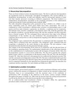
Figure 5-1 shows the UDP header. The fields of the UDP header are defined in
the sections that follow.
Source Port
The source port is a 16-bit number greater than 1023 that is chosen by a user of
a UDP based application. These ports are known as ephemeral ports because
they are only used for the lifetime of the connection (ephemeral means short-
lived). Ephemeral source port numbers are chosen by the IP stack and used by
the transport layer for the delivery of data to upper-layer applications. They
function essentially the same as the Ethernet Ethertype and the IP Protocol ID
field. When a source host sends data using UDP to a destination host, it
chooses an unused source port greater than 1023 to be placed into the UDP
Source Port field. The application on the destination station in turn uses this
port number in the Destination Port field when it sends data back to the host.
Destination Port
The destination port is also a 16-bit number, which may be greater or less than
1023. In the early ages of TCP/IP, most applications used what are called well-
known port numbers. Unlike ephemeral ports, applications will keep a well-
known port open for as long as the application is running. Well-known port
numbers are in the range of 0 to 1023. Hosts using these applications would use
a source (ephemeral) port greater than 1023 and a destination port (well-known)
between 0 and 1023. For example, DNS uses UDP port 53. A DNS server allo-
cates the use of port 53 on the local server. When a client sends a DNS request to
that server, it will use a source ephemeral port and a destination port of 53.
When the DNS server replies to the request, it will use the client’s ephemeral
port as the destination UDP port and port 53 as the source port. So many appli-
cations now use TCP and UDP that the defining line between which ports appli-
cations use is blurred. It is typical to see applications using ports ranging from 0
to 65535. Table 5-1 shows some typical UDP well-known application ports.
Table 5-1 Common UDP Application Ports
APPLICATION UDP PORT
NetBIOS Name Service 137
Simple Network Management Protocol 161
Domain Name Services 53
Routing Information Protocol 521
User Datagram Protocol 157
08 429759 Ch05.qxd 6/26/03 8:58 AM Page 157
Figure 5-1 UDP header.
NOTE A listing of all UDP and TCP ports can be found on the Internet Ports
Database at www.portsdb.org/.
UDP Length
The value of the UDP length field is the sum of the length of the UDP header
(8 bytes) and the length of the data it is carrying. A quick way of determining
the UDP length field is to subtract 20 bytes from the value in the IP length field.
Because the IP header is always 20 bytes long, the resulting value will always be
equal to the length of the UDP header and its data. For example, if IP is carrying
1,480 bytes, you know that UDP is carrying 1,452 bytes (1,480 – 20(IP) – 8(UDP
Header) = UDP data). Of course, you can always look at the UDP length field,
but sometimes it’s easier to just perform the subtraction in your head.
UDP Checksum
The UDP checksum field covers the entire UDP header and the data being car-
ried by UDP. The UDP header checksum is optional; an application does not
have to use it. Eliminating the UDP checksum calculation can sometimes
speed up packet processing on slow hosts. If the checksum is not used, the
sender must transmit the checksum as all ones. When a receiving station sees
all ones in the checksum field, it will not attempt to recalculate the checksum.
WARNING When you are making the decision to turn off UDP checksums,
it is important that an application have the ability to guarantee data integrity.
There is always the possibility that data could become corrupted after it is
received by the MAC layer. In that case, if UDP checksums are not enabled and
the application has no data integrity functions, then the data will be passed to
the application, which will have no knowledge that the data it is receiving is
corrupted.
16 bits
Source Port
UDP Length
Data
16 bits
Destination Port
UDP Checksum
158 Chapter 5
08 429759 Ch05.qxd 6/26/03 8:58 AM Page 158
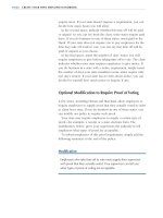
The UDP checksum includes something called the UDP pseudo-header. The
pseudo-header is a virtual extension to the UDP header, which the entire UDP
checksum is computed across. The pseudo-header is not included in the actual
header but used to provide another guarantee that the UDP data has been
received by the correct host. Figure 5-2 shows the UDP psuedo-header. When
a source transmits a UDP packet, it builds a virtual UDP packet including the
source and destination IP addresses, the IP Protocol ID, and the UDP Length
field. The UDP checksum field includes these virtual fields when it calculates
the checksum value. When the destination UDP layer receives the UDP data-
gram, it takes the source IP address, destination IP address, and protocol ID
from the IP header for use in recreating the virtual UDP psuedo-header. The
destination host literally rebuilds the same virtual UDP packet that the source
host used to calculate its UDP checksum. It then compares the checksum it cal-
culated to the checksum received in the packet to make sure they are the same.
Although you never actually see the pseudo-header in the UDP packet, it is
important to understand that this process exists. Psuedo-headers make the
UDP checksum more resilient in guaranteeing data integrity between hosts. By
disabling the UDP checksum, you may gain performance, but lose the ability
to provide data integrity to your applications, unless of course, the application
has a way of providing it.
Data
The data field of the UDP datagram contains the data the destination applica-
tion is to receive, the application being defined by the destination UDP port
number.
Figure 5-2 The UDP psuedo-header.
16 bits
32-Bit Source IP Address
32-Bit Destination IP Address pseudo-header
UDP header
UDP LengthProtocol IDZero
Source Port
UDP Length
Data
16 bits
Destination Port
UDP Checksum
User Datagram Protocol 159
08 429759 Ch05.qxd 6/26/03 8:58 AM Page 159
UDP Communication Process
Communications at the transport layer are sometimes called client/server
communications. Typically one host (the client) needs to use an application on
another host (the server).
NOTE Although there is no requirement for either host to actually be a server-
type machine, it is easier to view the communications processes in terms of a
client and a server.
When a client needs to use an application on a remote host using the UDP
protocol, it needs to know a couple pieces of information.
■■ The IP address of the host where the application resides
■■ The destination UDP port number of the application
There are several different methods through which a host can obtain the IP
address of a destination host. One is the Domain Name System (DNS); another
is the Windows Internet Naming System (WINS).
CROSS-REFERENCE I talk about these methods in Chapters 7 and 8.
For now, assume that a host knows that an application resides on another
host with the IP address of 172.16.1.15. After obtaining the IP address, it now
needs to know what the applications destination UDP port number is. All UDP
and TCP port numbers are stored in a file named the services file. On Unix sys-
tems, the services file is typically located in /etc/services. On Windows 2000
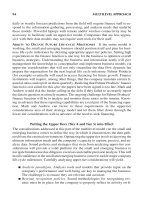
hosts, it can be found in c:\windows\system32\drivers\etc. Figure 5-3 shows
a typical Windows 2000 services file.
The services file contains all mappings of applications to port numbers
for both TCP and UDP. When a host needs to know the destination UDP or
TCP port of an application, it searches the services file to find the correct
port number. Custom applications install their respective UDP or TCP ports in
this file.
160 Chapter 5
08 429759 Ch05.qxd 6/26/03 8:58 AM Page 160
Figure 5-3 Windows 2000 services file. (continues)
# Copyright (c) 1993-1999 Microsoft Corp.
#
# This file contains port numbers for well-known services defined by IANA
#
# Format:
#
# <service name> <port number>/<protocol> [aliases ] [#<comment>]
#
echo 7/tcp
echo 7/udp
discard 9/tcp sink null
discard 9/udp sink null
systat 11/tcp users #Active users
systat 11/tcp users #Active users
daytime 13/tcp
daytime 13/udp
qotd 17/tcp quote #Quote of the day
qotd 17/udp quote #Quote of the day
chargen 19/tcp ttytst source #Character generator
chargen 19/udp ttytst source #Character generator
ftp-data 20/tcp #FTP, data
ftp 21/tcp #FTP. control
telnet 23/tcp
smtp 25/tcp mail #Simple Mail Transfer Protocol
time 37/tcp timserver
time 37/udp timserver
rlp 39/udp resource #Resource Location Protocol
nameserver 42/tcp name #Host Name Server
nameserver 42/udp name #Host Name Server
nicname 43/tcp whois
domain 53/tcp #Domain Name Server
domain 53/udp #Domain Name Server
bootps 67/udp dhcps #Bootstrap Protocol Server
bootpc 68/udp dhcpc #Bootstrap Protocol Client
tftp 69/udp #Trivial File Transfer
gopher 70/tcp
finger 79/tcp
http 80/tcp www www-http #World Wide Web
kerberos 88/tcp krb5 kerberos-sec #Kerberos
kerberos 88/udp krb5 kerberos-sec #Kerberos
hostname 101/tcp hostnames #NIC Host Name Server
iso-tsap 102/tcp #ISO-TSAP Class 0
rtelnet 107/tcp #Remote Telnet Service
pop2 109/tcp postoffice #Post Office Protocol - Version 2
pop3 110/tcp #Post Office Protocol - Version 3
sunrpc 111/tcp rpcbind portmap #SUN Remote Procedure Call
sunrpc 111/udp rpcbind portmap #SUN Remote Procedure Call
auth 113/tcp ident tap #Identification Protocol
uucp-path 117/tcp
nntp 119/tcp usenet #Network News Transfer Protocol
ntp 123/udp #Network Time Protocol
epmap 135/tcp loc-srv #DCE endpoint resolution
epmap 135/udp loc-sr #DCE endpoint resolution
netbios-ns 137/tcp nbname #NETBIOS Name Service
netbios-ns 137/udp nbname #NETBIOS Name Service
netbios-dgm 138/udp nbdatagram #NETBIOS Datagram Service
netbios-ssn 139/tcp nbsession #NETBIOS Session Service
imap 143/tcp imap4 #Internet Message Access Protocol
pcmail-srv 158/tcp #PCMail Server
snmp 161/udp #SNMP
snmptrap 162/udp snmp-trap #SNMP trap
print-srv 170/tcp #Network PostScript
bgp 179/tcp #Border Gateway Protocol
irc 194/tcp #Internet Relay Chat Protocol
ipx 213/udp #IPX over IP
ldap 389/tcp #Lightweight Directory Access Protocol
User Datagram Protocol 161
08 429759 Ch05.qxd 6/26/03 8:58 AM Page 161
Figure 5-3 Windows 2000 services file. (continued)
https 443/tcp MCom
https 443/udp MCom
microsoft-ds 445/tcp
microsoft-ds 445/udp
kpasswd 464/tcp # Kerberos (v5)
kpasswd 464/udp # Kerberos (v5)
isakmp 500/udp ike #Internet Key Exchange
exec 512/tcp #Remote Process Execution
biff 512/udp comsat
login 513/tcp #Remote Login
who 513/udp whod
cmd 514/tcp shell
syslog 514/udp
printer 515/tcp spooler
talk 517/udp
ntalk 518/udp
efs 520/tcp #Extended File Name Server
router 520/udp route routed
timed 525/udp timeserver
tempo 526/tcp newdate
courier 530/tcp rpc
conference 531/tcp chat
netnews 532/tcp readnews
netwall 533/udp #For emergency broadcasts
uucp 540/tcp uucpd
klogin 543/tcp #Kerberos login
kshell 544/tcp krcmd #Kerberos remote shell
new-rwho 550/udp new-who
remotefs 556/tcp rfs rfs_server
rmonitor 560/udp rmonitord
monitor 561/udp
ldaps 636/tcp sldap #LDAP over TLS/SSL
doom 666/tcp #Doom Id Software
doom 666/udp #Doom Id Software
kerberos-adm 749/tcp #Kerberos administration
kerberos-adm 749/udp #Kerberos administration
kerberos-iv 750/udp #Kerberos version IV
kpop 1109/tcp #Kerberos POP
phone 1167/udp #Conference calling
ms-sql-s 1433/tcp #Microsoft-SQL-Server
ms-sql-s 1433/udp #Microsoft-SQL-Server
ms-sql-m 1434/tcp #Microsoft-SQL-Monitor
ms-sql-m 1434/udp #Microsoft-SQL-Monitor
wins 1512/tcp #Microsoft Windows Internet Name Service
wins 1512/udp #Microsoft Windows Internet Name Service
ingreslock 1524/tcp ingres
l2tp 1701/udp #Layer Two Tunneling Protocol
pptp 1723/tcp #Point-to-point tunnelling protocol
radius 1812/udp #RADIUS authentication protocol
radacct 1813/udp #RADIUS accounting protocol
nfsd 2049/udp nfs #NFS server
knetd 2053/tcp #Kerberos de-multiplexor
man 9535/tcp #Remote Man Server
162 Chapter 5
08 429759 Ch05.qxd 6/26/03 8:58 AM Page 162
After an application finds out the destination UDP port of the application,
the following happens:
1. It chooses a port number greater than 1023 for use in the source UDP
port field.
2. Upon reception of the packet, the destination host examines the desti-
nation UDP port number to determine what application should receive
the UDP data.
3. When the application responds to the source host, it reverses the UDP
port numbers, placing the destination stations source UDP port in the
destination UDP port field and its own source UDP port in the source
field.
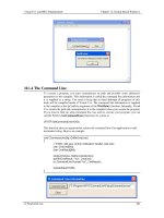
Figure 5-4 illustrates this process.
A DNS name resolution request is sent from host 192.168.1.100 to the DNS
server at 151.197.0.39. In frame 1 of the trace, the source UDP port is 3422 and
the destination port is the well-known DNS port for UDP of 53. In Frame 2 the
response from the DNS server to the client is from the source DNS port 53 to
the client’s UDP port 3422.
User Datagram Protocol 163
MICROSOFT PORT QUERY TOOL
Microsoft has a tool called Port Query (portqry.exe) that allows you to query
other hosts to see if the host is running a specific application over a well-
known UDP or TCP port. This tool is a great way to confirm that an application
is listening on a port and also to confirm that a firewall or router isn’t filtering
out traffic destined to certain ports. It can be downloaded at
www.microsoft.com.The following output shows the Port Query tool being used
to verify that my ISPs DNS server is in fact listening for DNS Name Resolution
Requests on UDP port 53:
C:\apps>portqry -n 151.197.0.39 -e 53 -p UDP
Querying target system called:
151.197.0.39
Attempting to resolve IP address to a name
IP address resolved to home4.bellatlantic.net
UDP port 53 (domain service): LISTENING
08 429759 Ch05.qxd 6/26/03 8:58 AM Page 163
Figure 5-4 UDP communication process.
Case Studies in UDP Communications
As I have discussed, UDP is a very simple protocol, providing only multiplex-
ing and data protection services to upper-layer applications. In a very simple
sense, it either works, or it doesn’t work. Its simplicity makes it very depen-
dent on the lower-layer networking services to operate without errors. UDP
has no methods to retransmit lost data or handle more than minimal flow con-
trol issues via ICMP Source Quench messages.
Client DNS Server
Client DNS Server
192.168.1.100 151.197.0.39 3422 53
Source IP Addr Dest IP Addr Source
UDP Port
Dest
UDP Port
192.168.1.100 151.197.0.393422 53
Dest IP Addr Source IP AddrDest
UDP Port
Source
UDP Port
164 Chapter 5
08 429759 Ch05.qxd 6/26/03 8:58 AM Page 164
Given all that, it is important to understand the reasoning behind why
applications use UDP over TCP when troubleshooting a problem. In this sec-
tion, I take a look at several application protocols that use UDP. I discuss the
basic functionality of the application and try to illustrate how the application
handles reliability services that UDP does not provide.
Name Resolution Services
In Chapters 7 and 8, I discuss two kinds of name resolution services in IP net-
works. One is used to resolve NetBIOS names, and the other is used to resolve
IP host names. Both are similar in nature. Both of these application protocols
use UDP as their method of transport rather than TCP. There are a couple of
reasons that UDP is a good choice for these applications:
■■ The first reason is that they are request/response applications. A single
request is sent and a single response is received. In file transfer applica-
tions, a server often sends multiple segments of data back to a client. A
protocol such as TCP can gather multiple small data segments and
group them into a single large TCP segment. This method of grouping
small segments together into one larger segment prevents wasting net-
work bandwidth on multiple small packets (see the sidebar “Packet
Efficiency” in this chapter). UDP has no such functionality. Every time
an application writes data to the UDP layer, a packet is generated. UDP
doesn’t provide segment assembly services, and therefore, is much
faster. Every time UDP receives data, it creates a UDP header and
passes its data down to the IP layer. For request/response applications,
UDP is fast and efficient because it doesn’t provide any reliability.
■■ Second, most request/response applications will retry their requests
if they don’t receive an answer. For example, if a client sends a DNS
name resolution request to a DNS name server and does not receive a
response, it will attempt the resolution process again and again, until
it eventually gives up. In Figure 5-5, you see a client sending repeated
DNS requests to a DNS server that is not responding. After the first
attempt in Frame 1, the client tries again after 1 second, 2 seconds,
5 seconds, and 9 seconds, and then finally gives up and displays the
Unknown host www.tracemasters.com message. Notice also that
the attempts are roughly doubled after each name resolution request.
The client host waits a little bit longer each time before making another
request in the hope that the network problem, which is preventing
name resolution, will be resolved. Here, the reliability is built into the
protocol itself. There is no need to use a protocol (like TCP) that pro-
vides reliability. The nature of most protocols like DNS is that they will
perform their own retransmissions of data.
User Datagram Protocol 165
08 429759 Ch05.qxd 6/26/03 8:58 AM Page 165
Figure 5-5 No DNS response.
Routing Information Protocol
The Routing Information Protocol, or RIP as it is commonly known, is used to
distribute routing information among routers on an IP network. It operates by
sending routing information in one or more IP broadcast packets. Routers
using the RIP protocol send out routing advertisements every 30 seconds.
Each packet can contain multiple route entries. When there are more route
entries than can fit in a single RIP packet, the routes are sent in consecutive RIP
packets. Each router sends out as many RIP packets during a single advertise-
ment interval as are necessary to advertise its entire routing table.
RIP is what is known as a distance vector routing protocol. A distance vector rout-
ing protocol simply advertises what routes it knows to other routers, with those
routers passing on information they have heard to other routers. The process con-
tinues until all routers have built a routing table of all routes in the network.
Since hosts depend on the network to provide end-to-end routing of data, it
would seem that it would be important enough for routing protocols such as RIP
to use a reliable protocol like TCP for advertising routing information. However,
RIP does not; it uses UDP. If a single RIP packet is lost, UDP will not retransmit
the data. Fortunately, because of the way RIP works, the loss of a single packet
does not affect the routing process. Routers listening to RIP broadcasts will not
automatically flag a route as unreachable if they miss a single RIP packet con-
taining the route entry. Listening routers typically wait a multiple of several
advertisement intervals before declaring a route unreachable. For example, RIP
advertises route entries every 30 seconds. A router listening for RIP advertise-
ments will delete a route from its route table only after not hearing an advertise-
ment for the route after three route advertisement intervals. In the case of RIP,
this amounts to 90 seconds until a router declares a route unreachable.
So why then doesn’t RIP use a reliable protocol like TCP? To understand
why a reliable protocol like TCP is unnecessary, examine Figure 5-6. The router
at 10.239.1.81 is advertising 109 separate route entries every 30 seconds via the
RIP protocol. In its second advertisement, you see only 100 route entries being
advertised, as the last RIP packet containing the last 9 entries is lost. 30 seconds
166 Chapter 5
08 429759 Ch05.qxd 6/26/03 8:58 AM Page 166
later you can again see the full 109 routes being advertised. There is no need to
retransmit this lost RIP broadcast because this is done automatically at the next
advertisement interval.
In essence, the reliability needed for the routing information is already built
into the protocol itself by way of its advertisement interval. Routing protocols
like RIP use UDP because of this built-in “reliability.” By its nature, RIP is
going to broadcast its routes whether or not a destination router receives them.
It simply doesn’t need a reliable transport to do what it is already going to do.
OSPF, another routing protocol, uses neither UDP nor TCP because it runs
directly over IP. Only in the most critical situations does a routing protocol use
a reliable protocol. BGP-4, the routing protocol behind the Internet backbone,
is one such protocol. BGP-4 uses TCP as its reliable transport protocol.
User Datagram Protocol 167
PACKET EFFICIENCY
All packet transmissions over a network have overhead associated with them.
For example, a user’s password may consist of only 20 bytes of data, but it
takes 46 bytes of overhead to transmit it over the network. Each protocol layer
adds its own overhead needed to do its job. Overhead is anything added to a
data transmission besides the data. Here is the amount of overhead at each
layer needed to carry a simple 20 bytes of data across the network using the
UDP protocol.
Ethernet (addressing, Ethertype, CRC) = 18 bytes
Internet Protocol Header = 20 bytes
UDP Header = 8 Bytes
Data = 20 bytes
Total Overhead = 46 bytes
Total Packet Length = 66 bytes
Packet efficiency is the percentage of the total packet length that is being
utilized for data. The more that is utilized, the better the efficiency is. Packet
efficiency is calculated by dividing the data length by the packet length.
10 bytes / 66 bytes = 15% Packet Efficiency
As you increase the amount of data that each packet is carrying, your packet
efficiency increases. If you start carrying the maximum amount of data in each
UDP packet, your efficiency is maximized. Here is the packet efficiency for
1,452 bytes of UDP data.
1,452 bytes / 1,518 bytes = 95% Packet Efficiency
The bottom line is that it is better to fill your packets with as much data as
possible before transmitting them across the network.
08 429759 Ch05.qxd 6/26/03 8:58 AM Page 167
Figure 5-6 Router RIP advertisements.
Frame Time Dst Other Addr Src Other Addr
Protocol Description
1 31.036494 255.255.255.255 10.239.1.81
RIP Response, 25 Entries (ver. 1)
2 32.03772 255.255.255.255 10.239.1.81
RIP Response, 25 Entries (ver. 1)
3 33.042707 255.255.255.255 10.239.1.81
RIP Response, 25 Entries (ver. 1)
4 34.040045 255.255.255.255 10.239.1.81
RIP Response, 25 Entries (ver. 1)
5 35.044908 255.255.255.255 10.239.1.81
RIP Response, 9 Entries (ver. 1)
6 51.632907 255.255.255.255 10.239.1.82
RIP Response, 25 Entries (ver. 1)
7 52.435522 255.255.255.255 10.239.1.80
RIP Response, 25 Entries (ver. 1)
8 52.637429 255.255.255.255 10.239.1.82
RIP Response, 8 Entries (ver. 1)
9 53.436705 255.255.255.255 10.239.1.80
RIP Response, 25 Entries (ver. 1)
10 54.437882 255.255.255.255 10.239.1.80
RIP Response, 25 Entries (ver. 1)
11 55.440118 255.255.255.255 10.239.1.80
RIP Response, 25 Entries (ver. 1)
12 56.443953 255.255.255.255 10.239.1.80
RIP Response, 9 Entries (ver. 1)
13 65.07658 255.255.255.255 10.239.1.81
RIP Response, 25 Entries (ver. 1)
14 66.077872 255.255.255.255 10.239.1.81
RIP Response, 25 Entries (ver. 1)
15 67.078963 255.255.255.255 10.239.1.81
RIP Response, 25 Entries (ver. 1)
16 68.080116 255.255.255.255 10.239.1.81
RIP Response, 25 Entries (ver. 1)
17 82.669596 255.255.255.255 10.239.1.82
RIP Response, 25 Entries (ver. 1)
18 83.674185 255.255.255.255 10.239.1.82
RIP Response, 8 Entries (ver. 1)
19 86.475979 255.255.255.255 10.239.1.80
RIP Response, 25 Entries (ver. 1)
20 87.477196 255.255.255.255 10.239.1.80
RIP Response, 25 Entries (ver. 1)
21 88.478409 255.255.255.255 10.239.1.80
RIP Response, 25 Entries (ver. 1)
22 89.479547 255.255.255.255 10.239.1.80
RIP Response, 25 Entries (ver. 1)
23 90.484427 255.255.255.255 10.239.1.80
RIP Response, 9 Entries (ver. 1)
24 99.121799 255.255.255.255 10.239.1.81
RIP Response, 25 Entries (ver. 1)
25 100.123108 255.255.255.255 10.239.1.81
RIP Response, 25 Entries (ver. 1)
26 101.124185 255.255.255.255 10.239.1.81
RIP Response, 25 Entries (ver. 1)
27 102.125813 255.255.255.255 10.239.1.81
RIP Response, 25 Entries (ver. 1)
28 103.130192 255.255.255.255 10.239.1.81
RIP Response, 9 Entries (ver. 1)
29 113.706383 255.255.255.255 10.239.1.82
RIP Response, 25 Entries (ver. 1)
30 114.710654 255.255.255.255 10.239.1.82
RIP Response, 8 Entries (ver. 1)
31 120.516427 255.255.255.255 10.239.1.80
RIP Response, 25 Entries (ver. 1)
30
second
interval
109 route entries from
10.239.1.81
100 route entries from
10.239.1.81
109 route entries from
10.239.1.81
30
second
interval
168 Chapter 5
08 429759 Ch05.qxd 6/26/03 8:58 AM Page 168
Simple Network Management Protocol
Simple Network Management Protocol (SNMP) is another application-layer
protocol that does not require a reliable transport. Used by network manage-
ment stations to query the status of devices, SNMP actually relies on failures in
the network in order to build its uptime statistics. Like RIP, it queries devices
on the network for information contained in their MIB tables. SNMP can
gather from devices such information as uptime, error counts, and interface
bandwidth statistics. The values it collects are stored in a database on the man-
agement station for further use in reports or alarms. When an SNMP network
management station does not receive a response from an SNMP query, it
attempts to query the device several more times before flagging the device as
down. It then, depending on its configuration, possibly creates an alarm con-
dition and notifies network administrators that the device is down. SNMP, like
RIP, by its nature is going to query network devices regardless of whether or
not they respond. When they respond, the management station knows that it
will be able to continue querying the device for various values in its MIB
tables. When a device stops responding, it will still query the device periodi-
cally to make sure it hasn’t come back online.
UDP and Firewalls
Unlike TCP, UDP is stateless. State refers to the ability of a protocol to provide
information about its connection status with another station. TCP does this
with something called sequence numbers and connection flags. The sequence
numbers and flags make it easy to track a TCP application through a firewall.
It is important to track where conversations are initiated to prevent the spoof-
ing of an application conversation. With UDP, this is difficult to do. Most fire-
wall administrators limit UDP traffic through their firewalls for exactly this
reason. Some applications, though, use UDP. DNS is one important protocol
that uses UDP and that cannot be filtered from most firewalls. Sometimes it is
difficult to determine what protocols and ports an application uses without
manually analyzing a packet trace of the application. Many times I have seen
applications using protocols and ports that the administrators didn’t even
know about. A simple packet capture during the execution of an application
can quickly reveal which protocols and ports it depends on.
CROSS-REFERENCE I talk about TCP sequence and acknowledgement
numbers in Chapter 6.
User Datagram Protocol 169
08 429759 Ch05.qxd 6/26/03 8:58 AM Page 169
TIP When troubleshooting connections through a firewall, a protocol analyzer
is an excellent tool to have on hand because by using it you can immediately
determine what ports and protocols are being blocked by a firewall.
The following case studies illustrate why you sometimes need to utilize
proper analysis techniques in order to diagnose application problems. When
an application fails due to a firewall or router blocking the traffic it requires, I
very often see time-consuming knowledge base searches performed on the
vendor’s Web sites in search of the answer. Sometimes the answer is that a
registry entry or configuration parameter needs to be changed, but it is impor-
tant to first understand what is happening that causes the application to fail. I
illustrate how to use a protocol analyzer to do just that in the following cases.
Case Study: Failed PCAnywhere Session
Upon the implementation of a new third-party firewall, my team and I imme-
diately received calls from the server administration group about their not
being able to access PCAnywhere sessions on their servers.
After getting an administrator on the phone and our protocol analyzer’s fil-
ters set up, we were able to capture a session between the administrator and
the server on which that person was trying to access a PCAnywhere session.
What we saw was several UDP packets from the client with no response from
the server. The UDP packets had a destination UDP port of 5632. It was imme-
diately obvious that the firewall was dropping these UDP packets. Unfortu-
nately, the firewall policy mirrored the corporate security policy that no UDP
packets are allowed through the firewall except for protocols that absolutely
needed UDP, protocols like DNS, which were critical to the functioning of the
network.
After doing a little research on Symantec’s Web site, we discovered that
UDP port 5632 was used only for obtaining the status of the PCAnywhere ser-
vice. The actual PCAnywhere sessions ran over TCP port 5631. We also found
a small registry entry that could be configured on PCAnywhere client
machines that told the software to continue connecting with TCP even if it did
not receive a response on the UDP status port (see the sidebar “PCAnywhere
Registry Fix”). Once the local administrators configured their machines with
this registry entry, they were able to access PCAnywhere because the local
software continued the connection processing using TCP even after never
receiving a UDP status response.
170 Chapter 5
08 429759 Ch05.qxd 6/26/03 8:58 AM Page 170
I’ve seen this situation more times than I care to count on networks that use
PCAnywhere for remote administration. It is a fine example of how under-
standing an application protocols and ports can aid in problem solving. Figure
5-7 illustrates how PCAnywhere sessions work. In Frame 1 the client sends a
UDP status frame to the server running PCAnywhere on port 5632. Only after
the server responds to the status frame does the client continue the connection
process using TCP port 5631.
Case Study: NFS Failures
Network File System (NFS) is another protocol that uses UDP. NFS is primar-
ily used on Unix systems and uses UDP port 2049. Unix systems also use other
UDP port services for several other applications known as Remote Procedure
Calls, or RPC. Clients using these RPC services do not know off-hand what
port the remote service will be running on. They use an RPC feature called
Port Mapper to find out. Figure 5-8 illustrates a situation we ran into after
migrating several Unix systems to a different location and putting them
behind a firewall.
Figure 5-7 PCAnywhere session.
User Datagram Protocol 171
PCANYWHERE REGISTRY FIX
To disable the pcAnywhere UDP status packets you need to modify the
following registry key:
HKEY_LOCAL_MACHINE\SOFTWARE\Symantec\pcAnywhere\CurrentVersion\System
You need to add the DWORD value TCPIPConnectIfUnknown and set the
value of this new entry to 1.
08 429759 Ch05.qxd 6/26/03 8:58 AM Page 171
Figure 5-8 NFS in action.
Unix administrators notified us that they could no longer mount remote
Unix volumes across the network. Figure 5-8 shows a packet capture of what
happened while we watched as they attempted to mount a remote Unix file
system volume.
Since we knew that Unix uses the NFS protocol, we could immediately see
that the firewall was permitting NFS traffic through. Frame 2 of the trace shows
Server B responding to an NFS call from Server A that was sent in Frame 1.
Frames 3, 4, 5, and 6 show some UDP traffic that is not being answered by Server
B. We can even see that the analyzer’s expert mode indicates the presence of one-
way traffic, which means that there is no response from the destination station.
We examined the detail of these one-way packets in Figure 5-9 and noticed
that they were RPC Requests to the Port Mapper service. These packets are
RPC requests asking the server what UDP port the Mount program is running
on. Normally the Port Mapper service would respond with the proper port.
We quickly realized that the firewall that was now between the two servers
was not permitting UDP port 111 (RPC) through the firewall; thus, the Port
Mapper service that relied on the RPC function, would not work. Once we
modified the firewalls ruleset to allow UDP port 111, the Unix administrators
were able to mount remote volumes.
172 Chapter 5
08 429759 Ch05.qxd 6/26/03 8:58 AM Page 172
Figure 5-9 RPC dropped.
I would like to reinforce once again how important it is to properly analyze
an application’s traffic during a problem. The previous case studies clearly
show the definitive diagnosis and solution to the problems. Many times simi-
lar results can be obtained by making multiple configuration changes until the
application starts working. The drawback to this random guesswork is that
when a similar problem occurs, you might try the same fix without any result.
Different problems sometimes manifest themselves with the same symptoms.
Without knowing the real cause of the problem by way of proper analysis, you
will never be able to translate that knowledge to other situations.
Traceroute Caveats
In Chapter 4, I discussed how the PING program uses ICMP Echo and Echo
Reply messages to query if a host is responsive or not. I also show how the
traceroute program uses these ICMP Echo messages to build a list of routers
along the path of the packets using TTL Expired messages. The traceroutes I
use in the Chapter 4 section on TTL are from the tracert program on a Microsoft
Windows 2000 station. If you happen to be analyzing a Unix system trace-
route, you might be scratching your head as to why you don’t see any ICMP
Echo Requests. You don’t see them because most Unix systems use UDP
instead of ICMP for traceroute.
User Datagram Protocol 173
08 429759 Ch05.qxd 6/26/03 8:58 AM Page 173
To explain actually requires some history. The original traceroute program
used ICMP. One of the first times the developers tested the traceroute program
they noticed that routers were not sending back ICMP TTL Expired messages.
After some quick conversations to router vendors, they found out that the
router code was taking the requirement of not sending ICMP error messages to
ICMP error packets quite literally. Instead of not responding to just ICMP error
packets, the routers were not sending ICMP error messages for any ICMP
packets, including ICMP echoes that were really not error packets but simple
diagnostic messages. Because of this problem, the original traceroute pro-
grams written for Unix systems use UDP instead of ICMP.
TIP When analyzing latency from a Unix system, for example, this history is
good to know because you won’t see any ICMP packets. Instead, you will see
UDP packets.
Summary
UDP is a very simple protocol that provides only multiplexing and data pro-
tection functionality. It is important to understand how, when using a nonreli-
able transport protocol, an application must take on the responsibility of
reliability itself. In the next chapter, on TCP, I take a look at how reliability,
flow control, and myriad other features are implemented to provide function-
ality that UDP, or even IP, cannot provide.
174 Chapter 5
08 429759 Ch05.qxd 6/26/03 8:58 AM Page 174
175
As you move up higher and higher into each layer of the OSI model, protocols
become more complex. TCP is no exception to this statement. Its complexity
derives from TCP’s rich set of features and functionality. By not learning its
inner functions, you risk missing the ability to completely understand the pro-
tocol, which, in troubleshooting scenarios, can be deadly. This chapter seeks to
help you understand TCP from the inside out.
Introduction to TCP
Chapter 6 is broken down into four main sections.
■■ First is the one you are reading, the introduction. In it I discuss TCP at
the 10,000-foot level, briefly glancing over its many intricacies. TCP is
a difficult protocol to explain without getting into its many intricate
details. I have purposely left out many of these details in the first sec-
tion. I simply want you to be familiar with their existence before we
talk about their use. Thus, I immediately describe the TCP Header,
which will be the basis for our discussion on the rest of the protocol’s
functionality. I also talk about what a reliable transport protocol does
and what it needs to be able to do its job. Again, these subjects will be
at a very broad level so that the reader may glean a look at what is to
come later in the chapter.
Transmission Control Protocol
CHAPTER
6
09 429759 Ch06.qxd 6/26/03 8:58 AM Page 175
■■ Second, I talk about the connection-oriented nature of TCP, how it
opens, closes, and handles connection problems between hosts.
■■ Third, I talk in depth about how TCP handles flow control between two
hosts and what happens if packets are lost during a data transfer.
■■ Finally, I wrap up the chapter on TCP with examples analyzing applica-
tions that run over TCP.
Each of these four sections includes numerous case studies. The best way to
illustrate a protocol is by example. Many a skilled network administrator has
gained his experience from configuring workstations, building servers, and
configuring routers. As you move up into the higher layers, however, there is
often nothing to configure. The only way to learn is by example, by watching
the protocols themselves in action. TCP cannot be understood without taking
the time to analyze packet by packet the transactions occurring between hosts.
TCP takes time.
NOTE I whole-heartedly encourage readers to pick up a copy of W. Richard
Stevens’ TCP/IP Illustrated, Volume 1 (Addison-Wesley January 1994). Stevens
does an excellent job of extrapolating on almost every nuance of the TCP
protocol. The book is an invaluable reference for the protocol and should be
a part of any network analyst’s book collection.
Requirements for a Reliable Transport Protocol
In Chapter 5, I discussed how UDP provides only multiplexing and data
protection services to upper-layer protocols and data. TCP also provides the
same services as UDP, using source and destination port numbers, a TCP
checksum, and even the same pseudo-header that UDP uses to verify the
data’s destination endpoint and to ensure data integrity. However, unlike
UDP, TCP is a connection-oriented, reliable transport protocol. TCP has the
ability to track data transmissions and, if necessary, retransmit them. It has the
ability to manage flow control between a sender and receiver. Unlike UDP,
which was only able to utilize ICMPs Source Quench message, TCP can inform
an endpoint of its data reception capabilities in a very granular manner. TCP
has other functionality that allows it to provide better service to applications
regardless of their traffic type. The next sections present several scenarios that
a reliable, connection-oriented transport protocol needs to handle.
176 Chapter 6
09 429759 Ch06.qxd 6/26/03 8:58 AM Page 176
Fast Sender and Slow Receiver
A host that is receiving data from another host may need to inform the send-
ing host of the need to adjust its rate of transmission. There may be several
reasons that a host cannot receive data at the same rate as a sender transmits it.
■■ The host may have less processing power than the sender.
■■ Its TCP/IP stack may be busy servicing many other concurrent
communications.
■■ It also may have an application that is not retrieving data from the
transport layers buffers quickly enough.
An application using UDP has only the ability to use the ICMP Source
Quench message to inform a host to slow down its rate of transmission. Unfor-
tunately, the ICMP Source Quench message does not contain any information
that would allow it to tell a host how long it needs it to slow down for. Conges-
tion conditions inside of a host can change very quickly. Ahost unable to receive
any data could be ready to receive more data in under a half a second. ICMP
Source Quench messages are a brute force method of congestion control. A
reliable transport protocol needs a granular feedback mechanism to inform
senders of exactly how much data they are able to accept at any given time. With
this information, a sending host can adjust its rate of transmission to suit the
needs of a receiving host. Later in the chapter, you will see how TCP’s window
size advertisement does just this.
Packet Loss
In some of the previous chapters I mention several conditions, such as conges-
tion or media errors, that may cause packets to be dropped on their way from
a sender to a receiver. Any number of circumstances could cause packet loss on
a network. Whether packet loss occurs on the network, inside of a router, or on
the way up the stack to an application is not a concern to the transport layer. A
reliable transport layer is concerned only with the end-to-end data transfer.
Reliability by the transport layer is provided by its ability to retransmit data
that has not been received by a destination host. So, in order for a host’s TCP
stack to recognize packet loss, it must have a method of tracking individual
segments of data that it transmits. It does this by sending with every segment
a unique sequence number. When a destination host’s TCP stack receives the
data segment, it sends back an acknowledgment message telling the sender
that it received the data segment sent by the host. This acknowledgment mes-
sage tells the source that the host’s TCP stack, in fact, received the data with a
specific sequence number. If a sending host does not receive an acknowledg-
ment for a sequenced data segment, it assumes that the data segment was lost
in route to the destination. After waiting a certain time interval, the sending
host’s TCP stack will retransmit the last data segment.
Transmission Control Protocol 177
09 429759 Ch06.qxd 6/26/03 8:58 AM Page 177
NOTE Remember, however, that reliability in a reliable protocol does not
mean that data transmission is guaranteed. Although a reliable protocol will do
its best to mitigate problem conditions on a network, it cannot handle every
situation that is likely to occur. For example, an interface on a router may be
intermittently dropping data packets. If a packet is dropped, the TCP protocol
will retransmit the packet. Assuming that the interface problem is intermittent,
there is a good chance that the retransmitted packet will make it to the
destination host. If the interface fails completely and stops passing all traffic,
the TCP protocol on the sending host can retransmit lost data indefinitely and it
will not be successful until the routers interface module is replaced. This
situation is what we call best effort. A reliable transport protocol can really
only provide a best effort attempt at data transmission because it, like other
protocols, also relies on the layers below it to do their job correctly.
Data Duplication
I want to expand on the topic of packet loss. Assume that a packet on a
network is lost. TCP retransmits the lost data segment, and all is well. Maybe.
What happens if the destination host receives the original segment a split
second after TCP retransmits the lost segment? Now the destination host is
going to receive the same data twice, and unless the application has some way
of also sequencing data, it is also going to receive the same data twice. This sit-
uation could possibly corrupt an application if there isn’t some way to detect
duplicate data. Fortunately, there is. As I said previously, TCP sends every data
segment with a unique sequence number. When a receiving host’s TCP stack
notices the same sequence number being received a second time, it simply
drops the duplicate data. This example is a fine illustration of the types of
services that TCP provides to an application. If not for TCP’s data sequencing
function, an application would have to provide the same functionality. And in
order for an application to perform the same services as TCP, the programmers
would have to include code in the application that would, in effect, do the
exact same thing that TCP does already. So, why not just write applications to
take advantage of the services that TCP already offers?
Priority Data
Often when two hosts are transferring data between them it is through an
interactive user application. Telnet is a fine example of an interactive applica-
tion. Telnet uses control characters to handle screen formatting, keystroke
echoing functions, and other data manipulation. It is sometimes imperative for
real-time applications like Telnet to prioritize certain data, such as control
characters, over regular data. The TCP protocol allows an application to do
178 Chapter 6
09 429759 Ch06.qxd 6/26/03 8:58 AM Page 178
this with something called the urgent pointer. The urgent pointer lets an appli-
cation specify data that is urgent. The application then is able to retrieve that
data and process it before other data in the stream. Applications that make use
of data that is by nature a priority would never be able to operate over a sim-
ple unreliable transport protocol like UDP. The urgent pointer is not often
used because TCP has a function called the Push bit that provides similar func-
tionality to the urgent pointer. I discuss the Push bit in a later section of this
chapter.
Out-of-Order Data
In redundant networks, it is not uncommon to have more than one possible
network path between a sender and receiver. Because of this, it is quite possi-
ble that packets could take different paths upon traveling to their final desti-
nation. Some networks utilize parallel links that transmit packets in a
round-robin fashion across both links. This type of transmission allows equal
distribution of traffic over both links.
Assume that an application that transmits files between a source and desti-
nation host is using UDP as its transport protocol. Further, assume that the
network between the source and destination has multiple network paths.
What happens when a stream of data packets arrives in a different order from
which they were sent? Unless the source application provided some method of
numbering each data segment with a unique sequence number, the destina-
tion application will have no way of telling that the data segments it has
received are in the wrong order. This situation could lead to serious data cor-
ruption because the data will be written to the application in the wrong order.
Imagine a situation where each packet contains financial bank data for indi-
vidual bank accounts. It’s pretty easy to see what a disastrous affect this could
have on application data. A requirement for the proper ordered delivery of
data is precisely why application developers choose to write their applications
over a reliable protocol like TCP. TCP adds a sequence number to each seg-
ment of data before sending it. These sequence numbers allow the receiver to
easily reorder the data segments into the proper order before delivering them
to the upper-layer application.
Each of the situations discussed in the previous sections has led to the
requirements for developing the TCP protocol as it exists today. In the next sec-
tion, I discuss where these requirements are implemented in the TCP packet
header. Then, after you understand where these services are implemented, I
discuss how each of them actually works.
The TCP Header
The TCP header is 20 bytes long and contains a number of data fields. Figure 6-1
illustrates these fields. Their descriptions are given in the sections that follow.
Transmission Control Protocol 179
09 429759 Ch06.qxd 6/26/03 8:58 AM Page 179
Figure 6-1 TCP header.
Source Port
The source port is a 16-bit number greater than 1023 that is chosen by a user of
a TCP-based application. As is the case with UDP, these ports are ephemeral
ports—they are short-lived. The source port number is used by the transport
layer in delivering data to upper-layer applications. It functions essentially the
same way as the Ethernet Ethertype and the IP Protocol ID field. When a
source host uses TCP to send data to a destination host, it chooses an unused
port number over 1023, which is placed in the TCP Source Port field. The
application on the destination station will, in turn, use this port number in the
Destination Port field when it sends data back to the host.
Destination Port
The destination port is also a 16-bit number, which may be greater or less than
1023. In the early ages of TCP/IP, most applications used what are called well-
known port numbers. Well-known port numbers were in the range of 0 to
1023. In early versions of TCP on Unix systems, only superuser or root-level
users were able to create ports in the well-known range (0–1023). Although not
a standard, this convention has stayed with developers of TCP applications.
Users of these applications running on well-known port numbers will use
ephemeral port numbers greater than 1023. Table 6-1 shows some typical TCP
well-known application ports.
32-bit Acknowledgment Number
TCP Options
Data
16-bit Window Size
Destination Port
32-bit Sequence Number
16 bits 16 bits
Source Port
16-bit Urgent Pointer16-bit TCP Checksum
4-bit header
length
reserved
(6 bits)
Connection
Flags
180 Chapter 6
09 429759 Ch06.qxd 6/26/03 8:58 AM Page 180
Table 6-1 Example of TCP Ports
APPLICATION TCP PORT
Hypertext Transport Protocol (HTTP) 80
File Transfer Protocol 21, 20
Telnet 23
NetBIOS session 139
NOTE Due to the growth in the number of applications running over TCP, it is
not uncommon for applications to run on ports outside of the 0–1023 range.
You will, however, usually only see clients allocate source ports that are greater
than 1023.
Sequence Number
The sequence number is a 32-bit number that identifies the first byte of data
being sent in a TCP data segment. Unlike other block-based transport proto-
cols that sequence packets, TCP sequences bytes. Each byte being transmitted
contains its own unique sequence number.
Acknowledgment Number
The acknowledgment number is a 32-bit number that indicates to a sending
station the next byte sequence that it expects to receive from the sender. When
TCP receives a sequence of bytes from a sender, it adds the data segment’s
sequence number to the amount of bytes received to come up with the
acknowledgment number.
Header Offset
The Header Offset field is 4 bits long and represents the length of the TCP
header in the number of 32-bit words (4 bytes). A TCP header without any
options has a length of 20 bytes, which would be indicated by a header offset
value of 5 (5 × 4 = 20 bytes).
Reserved Bits
The current IP version 4 specification reserves the 6 bits after the 4-bit header
offset. These reserved bits are usually set to all zeros. There is a current pro-
posal to use these bits for the purposes of Explicit Congestion Notification.
Transmission Control Protocol 181
09 429759 Ch06.qxd 6/26/03 8:58 AM Page 181