The Art of Error Correcting Coding phần 9 potx
Bạn đang xem bản rút gọn của tài liệu. Xem và tải ngay bản đầy đủ của tài liệu tại đây (455.85 KB, 27 trang )
COMBINING CODES AND DIGITAL MODULATION 209
For systems that require high spectral efficiency, uncoded bits may be assigned to parallel
branches in the trellis.
9.2.1 Set partitioning and trellis mapping
Bit labels assigned to the signal points are determined from a partition of the constellation.
A2
ν
-th modulation signal set S is partitioned in ν levels. For 1 ≤ i ≤ ν,atthei-th
partition level, the signal set is divided into two subsets S
i
(0) and S
i
(1) such that the
intraset distance, δ
2
i
, is maximized. A label bit b
i
∈{0, 1} is associated with the subset
choice, S
i
(b
i
),atthei-th partition level. This partitioning process results in a labeling
of the signal points. Each signal point in the set has a unique ν-bit label b
1
b
2
b
ν
,
and is denoted by s(b
1
,b
2
, ,b
ν
). With this standard (Ungerboeck) partitioning of a
2
ν
-th modulation signal constellation, the intraset distances are in nondecreasing order
δ
2
1
≤ δ
2
2
≤···≤δ
2
ν
. This strategy corresponds to a natural labeling for M-PSK modulations,
that is, binary representations of integers whose value increases clockwise (or counterwise).
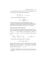
Figure 9.8 shows a natural mapping of bits to signals for the case of 8-PSK modulation,
with δ
2
1
= 0.586, δ
2
2
= 2, and δ
2
3
= 4.
Ungerboeck regarded the encoder “simply as a finite-state machine with a given number
of states and specified state transitions”. He gave a set of pragmatic rules to map signal
subsets and points to branches in a trellis. These rules can be summarized as follows:
Rule 1:
All subsets should occur in the trellis with equal frequency.
Rule 2:
State transitions that begin and end in the same state should be assigned subsets
separated by the largest Euclidean distance.
Rule 3:
Parallel transitions are assigned signal points separated by the largest Euclidean dis-
tance (the highest partition levels).
The general structure of a TCM encoder is shown in Figure 9.9. In the general case of a
rate (ν −1)/ν TCM system, the trellis structure is inherited from a k/(k +1) convolutional
encoder. The uncoded bits introduce parallel branches in the trellis.
Example 9.2.1 In this example, a 4-state rate-2/3 TCM system is considered. A constellation
for 8-PSK modulation is shown in Figure 9.8. The spectral efficiency is µ = 2 bits/symbol.
A block diagram of the encoder is shown in Figure 9.10. The binary convolutional code is
the same memory-2 rate 1/2 code that was used in Chapter 5. Note from Figure 9.11 that
the trellis structure is the same as that of the binary convolutional code, with the exception
that every branch in the original diagram is replaced by two parallel branches associated
with the uncoded bit u
1
.
210 COMBINING CODES AND DIGITAL MODULATION
b = 0
2
b = 0
2
2
000100
1
b =
1
b = 0
312
b b b =
b = 1
2
b = 1
010
110
001011
111101
1
b = 1
3
b = 0
3
b = 0
3
b = 1
3
b = 1
3
b = 0
3
b = 0
3
b = 1
3
Figure 9.8 Natural mapping of an 8-PSK constellation.
(b , , b )
k+2
n
k+12
(b , b , , b )
1
convolutional
encoder
Rate k/(k + 1)
k bits
(coded)
(uncoded)
(x,y)
Selection of
signal subset
Selection of point
in the subset
2 -th modulation
n
−1−k bitsn
Figure 9.9 General encoder of rate-(ν −1)/ν trellis-coded modulation.
COMBINING CODES AND DIGITAL MODULATION 211
0
DD
1
u
u
b
b
b
1
2
3
8-PSK
natural
mapping
x(b), y(b)
1
2
Figure 9.10 Encoder of a 4-state rate-2/3 trellis-coded 8-PSK modulation.
11
00 00
01 01
10 10
000
100
011
111
000
100
011
111
010
110
001
101
11
001 101
010
110
Figure 9.11 Trellis structure of a rate-2/3 trellis-coded 8-PSK modulation based on the
encoder of Figure 9.10.
9.2.2 Maximum-likelihood decoding
The Viterbi algorithm
2
can be applied to decode the most likely TCM sequences, provided
the branch metric generator is modified to include parallel branches. Also, the selection of
the winning branch and surviving uncoded bits should be changed. The survivor path (or
trace-back) memory should include the (ν −1 −k) uncoded bits as opposed to just one
bit for rate 1/n binary convolutional codes. It is also important to note that in 2
ν
-th PSK
or QAM modulation, the correlation metrics for two-dimensional symbols are of the form
x
p
x
r
+ y
p
y
r
,where(x
p
,y
p
) is a reference signal point in the constellation and (x
r
,y
r
) is
2
The Viterbi algorithm is discussed in Sections 5.5 and 7.2.
212 COMBINING CODES AND DIGITAL MODULATION
the received signal point. All other implementation issues discussed in Sections 5.5 and 7.2
apply to TCM decoders.
9.2.3 Distance considerations and error performance
The error performance of TCM can be analyzed in the same way as for convolutional
codes. That is, a weight-enumerating sequence can be obtained from the state diagram of
the TCM encoder, as in Section 5.3. The only difference is that the powers are not integers
(Hamming distances) but real numbers (Euclidean distances). Care needs to be taken of the
fact that the state transitions contain parallel branches. This means that the labels of the
modified state diagram contain two terms. See Biglieri et al. (1991).
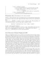
Example 9.2.2 Figure 9.12 shows the modified state diagram for the 4-state TC 8-PSK
modulation of Example 9.2.1. The branches in the trellis have been labeled with integers
corresponding to the eight phases of the modulation signals. To compute the weight enu-
merating sequence T(x), the same procedure as in Section 5.3 is applied. Alternatively,
by directly analyzing the trellis structure in Figure 9.13, it can be deduced that the MSED
between coded sequences is
D
2
C
= min{D
2
par
,D
2
tre
}=3.172,
which, when compared to an uncoded QPSK modulation system with the same spectral
efficiency of 2 bits/symbol, gives an asymptotic coding gain of 2 dB.
1,5
0,4
3,7
0,4
1,5
2,6
3,7
2,6
2
4
31
5
6
0
7
a = d(0,4) = 2
b = d(0,1) = 0.765
c = d(0,2) = 1.414
d = d(0,3) = 1.848
S
SS
mm
m
T(x)
S
1
init
(0)
(2)
(1)
(3)
3
21
S
final
(0)
(x)
(x)
(x)
4x
2 + 2x
a
2x + 2x
d
4x
d
b
2x + 2x
bc
2x + 2x
bc
c
2x + 2x
bc
Figure 9.12 The modified state diagram of a 4-state TC 8-PSK modulation scheme.
COMBINING CODES AND DIGITAL MODULATION 213
11 11 11
00
01
10
11
00
01
10
000
100
011
111
000
100
011
111
010
110
001
101
001 101
010
110
00
01
10
000
100
011
111
000
100
011
111
010
110
001
101
001 101
010
110
00
01
10
000
100
011
111
000
100
011
111
010
110
001
101
001 101
010
110
D = 4
par
2
2
D = 0.586 + 2 + 0.586 = 3.172
tre
Figure 9.13 Two paths at minimum squared Euclidean distance in the trellis of
Example 9.2.1.
9.2.4 Pragmatic TCM and two-stage decoding
For practical considerations, it was suggested in Viterbi et al. (1989), Zehavi and Wolf
(1995) that the 2
ν
-th modulation signal constellations be partitioned in such a way that
the cosets at the top two partition levels are associated with the outputs of the standard
memory-6 rate-1/2 convolutional encoder. This mapping leads to a pragmatic TCM system.
With respect to the general encoder structure in Figure 9.9, the value of k = 1 is fixed,
as shown in Figure 9.14. As a result, the trellis structure of pragmatic TCM remains the
same, as opposed to Ungerboeck-type TCM, for all values of ν>2. The difference is that
the number of parallel branches ν −2 increases with the number of bits per symbol. This
suggests a two-stage decoding method in which, at the first stage, the parallel branches in the
trellis “collapse” into a single branch and a conventional off-the-shelf Viterbi decoder (VD)
used to estimate the coded bits associated with the two top partition levels. In a second
decoding stage, based on the estimated coded bits and the positions of the received symbols,
the uncoded bits are estimated. Figure 9.15 is a block diagram of a two-stage decoder of
pragmatic TCM.
In Morelos-Zaragoza and Mogre (2001), a symbol transformation is applied to the input
symbols that enables the use of a VD without changes in the branch metric computation
stage. The decoding procedure is similar to that presented in Carden et al. (1994), Pursley
and Shea (1997), with the exception that, with symbol transformation, the Viterbi algorithm
can be applied as if the signals were BPSK (or QPSK) modulated. This method is described
below for M-PSK modulation.
Specifically, let (x, y) denote the I and Q coordinates of a received M-PSK symbol with
amplitude r =
x
2
+ y
2
and phase φ = tan
−1
(y/x). On the basis of φ, a transformation is
214 COMBINING CODES AND DIGITAL MODULATION
2 -ary
n
Memory-6 Rate-1/2
convolutional encoder
g = (1111001)
0
1
g = (1011011)
1 bit
n − 2 bits
bits-to-signal
mapping for
modulation
x
y
u
u
v
v
2
1
1
2
Figure 9.14 Block diagram of an encoder of pragmatic TCM.
Sector
delay
Rate-1/2
viterbi
decoder
Coset
mapping
x
y
x’
y’
LUT
Sector
mapping
Sector
Rate-1/2
encoder
Intra-coset
select
(LUT)
Coset
index
u
u
1
2
Figure 9.15 Block diagram of a two-stage decoder of pragmatic TCM.
applied such that the M-PSK points are mapped into “coset” points labeled by the outputs
of a rate-1/ 2 64-state convolutional encoder.
For TCM with M-th PSK modulation, M = 2
ν
, ν>2, let ξ denote the number of coded
bits per symbol,
3
where ξ = 1, 2. Then the following rotational transformation is applied
to each received symbol, (x, y), to obtain an input symbol (x
,y
) to the VD,
x
= r cos
2
ν−ξ
(φ − )
,
y
= r sin
2
ν−ξ
(φ − )
, (9.5)
where is a constant phase rotation of the constellation that affects all points equally.
Under the transformation (9.5), a 2
m−ξ
-PSK coset in the original 2
m
-PSK constellation
“collapses” into a coset point in a 2
ξ
-PSK coset constellation in the x
− y
plane.
Example 9.2.3 A rate-2/3 trellis-coded 8-PSK modulation with 2 coded bits per symbol is
considered. Two information bits (u
1
,u
2
) are encoded to produce three coded bits (u
2
,v
2
,v
1
),
3
The case ξ = 2 corresponds to conventional TCM with 8-PSK modulation. The case ξ = 1isusedinTCM
with coded bits distributed over two 8-PSK signals, such as the rate-5/6 8-PSK modulation scheme proposed in
the DVB-DSNG specification (ETSI 1997).
COMBINING CODES AND DIGITAL MODULATION 215
which are mapped onto an 8-PSK signal point, where (v
2
,v
1
) are the outputs of the standard
rate-1/2 64-state convolutional encoder.
4
The signal points are labeled by bits (u
2
,v
2
,v
1
)
and the pair (v
2
,v
1
) is the index of a coset of a BPSK subset in the 8-PSK constellation, as
shown at the top of Figure 9.16.
In this case φ
= 2φ and, under the rotational transformation, a BPSK subset in the
original 8-PSK constellation collapses to a coset point of the QPSK coset constellation in
the x
− y
plane, as shown in Figure 9.16. Note that both points of a given BPSK coset
have the same value of φ
. This is because their phases are given by φ and φ +π .
The output of the VD is an estimate of the coded information bit, u
1
. To estimate the
uncoded information bit, u
2
, it is necessary to reencode u
1
to determine the most likely coset
index. This index and a sector in which the received 8-PSK symbol lies can be used to decode
u
2
. For a given coset, each sector S gives the closest point (indexed by u
2
) in the BPSK pair
to the received 8-PSK symbol. For example, if the decoded coset is (1,1) and the received
symbol lies within sector 3, then u
2
= 0, as can be verified from Figure 9.16.
001
000
011
010
111
100
x
y
S = 0
S = 1S = 2
S = 3
S = 4
S = 5 S = 6
S = 7
101 110
000100
x
y
001
x
y
011
111
x
y
010
x
y
101 110
000100
x
y
001
x
y
011
111
x
y
010
x
y
101 110
COSET 00 COSET 01 COSET 11 COSET 10
Figure 9.16 Partitioning of an 8-PSK constellation (ξ = 2) and coset points.
4
v
1
and v
2
are the outputs from generators 171 and 133, in octal, respectively.
216 COMBINING CODES AND DIGITAL MODULATION
1
e
-05
1
e
-04
1
e
-03
1
e
-02
6 6.5 7 7.5 8 8.5 9 9.5 10 10.5 11 11.5 12 12.5 13
BER
Es
/
No
(dB)
"TC8PSK_23_SSD"
"TC8PSK_23_TSD"
"QPSK"
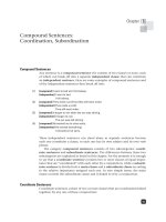
Figure 9.17 Simulation results of MLD versus two-stage decoding for pragmatic 8-PSK
modulation.
Figure 9.17 shows simulation results of MLD (with the legend “TC8PSK
23 SSD”) and
two-stage decoding of pragmatic TC-8PSK (legend “TC8PSK
23 TSD”). With two-stage
decoding, a loss in performance of only 0.2 dB is observed compared with MLD.
A similar transformation can be applied in the case of M-QAM; the difference is that
the transformation is based solely on the I-channel and Q-channel symbols. That is, there
is no need to compute the phase. An example is shown in Figure 9.18 for TC 16-QAM
with ξ = 2 coded bits per symbol. The coded bits are now the indexes of cosets of QPSK
subsets. The transformation of 16-QAM modulation (ξ = 2) is given by a kind of “modulo
4” operation:
x
=
x, |x|≤2;
(x − 4), x ≥ 2;
(x + 4), x < 2,
y
=
y, |y|≤2;
(y − 4), y ≥ 2;
(y + 4), y < 2.
Finally, it is interesting to note that a pragmatic TCM system with a turbo code as
component code was recently proposed in Wahlen and Mai (2000).
COMBINING CODES AND DIGITAL MODULATION 217
x
y
00110111
1111
1011
00100110
1110
1010
00010101
1101 1001
00000100
1100 1000
1
3
–1–3
–3
–1
13
S = 0
S = 1
S = 2
S = 3
S = 4
S = 5
S = 6
S = 7
S = 8
Figure 9.18 16-QAM constellation for pragmatic TCM with two-stage decoding.
9.3 Multilevel coded modulation
The idea in the MCM scheme of Imai and Hirakawa (1977) is to do a binary partition of
a2
ν
-ary modulation signal set into ν levels. The components of codewords of ν binary
component codes C
i
,1≤ i ≤ ν, are used to index the cosets at each partition level. One of
the advantages of MCM is the flexibility of designing coded modulation schemes by coordi-
nating the intraset Euclidean distances, δ
2
i
, i = 1, 2, ,ν, at each level of set partitioning,
and the minimum Hamming distances of the component codes. Wachsmann et al. (1999)
have proposed several design rules that are based on capacity (by applying the chain rule
of mutual information) arguments. Moreover, multilevel codes with long binary component
codes, such as turbo codes or LDPC codes, were shown to achieve capacity (Forney 1998;
Wachsmann et al. 1999).
It is also worthwhile noting that while binary codes are generally chosen as component
codes, that is, the partition is binary, the component codes can be chosen from any finite field
GF(q) matching the partition of the signal set. Another important advantage of multilevel
coding is that (binary) decoding can be performed separately at each level. This multistage
decoding results in greatly reduced complexity, compared with MLD for the overall code.
9.3.1 Constructions and multistage decoding
For 1 ≤ i ≤ ν,letC
i
denote a binary linear (n, k
i
,d
i
) code. Let ¯v
i
= (v
i1
,v
i2
, ,v
in
) be
a codeword in C
i
,1≤ i ≤ ν. Consider a permuted time-sharing code π(|C
1
|C
2
| |C
ν
|),
with codewords
¯v =
v
11
v
21
v
ν1
v
12
v
22
v
ν2
v
1n
v
2n
v
νn
.
Each ν-bit component in ¯v is the label of a signal in a 2
ν
-ary modulation signal set S.
Then
s(¯v) = (s(v
11
v
21
v
ν1
), s(v
12
v
22
v
ν2
), . . . , s(v
1n
v
2n
v
νn
)
is a sequence of signal points in S.
218 COMBINING CODES AND DIGITAL MODULATION
The following collection of signal sequences over S,
=
{
s(¯v) :¯v ∈ π(|C
1
|C
2
| |C
ν
|)
}
,
forms a ν-level modulation code over the signal set S or a ν-level coded 2
ν
-ary modulation.
The same definition can be applied to convolutional component codes.
The rate (spectral efficiency) of this coded modulation system, in bits/symbol, is
R = (k
1
+ k
2
+···+k
ν
)/n.
The MSED of this system, denoted by D
2
C
(), is given by Imai and Hirakawa (1977)
D
2
C
() ≥ min
1≤i≤ν
{d
i
δ
2
i
}. (9.6)
Example 9.3.1 In this example, a three-level block coded 8-PSK modulation system is con-
sidered. The encoder structure is depicted in Figure 9.19. Assuming a unit-energy 8-PSK
signal set, and with reference to Figure 9.8, note that the MSED at each partition level is
δ
2
1
= 0.586, δ
2
2
= 2 and δ
2
3
= 4.
The MSED of this coded 8-PSK modulation system is
D
2
C
() = min{d
1
δ
2
1
,d
2
δ
2
2
,d
3
δ
2
3
}=min{8 ×0.586, 2 ×2, 1 ×4}=4,
and the coding gain is 3 dB with respect to uncoded QPSK. The trellises of the component
codes are shown in Figure 9.20. The overall trellis is shown in Figure 9.21.
As mentioned in the preceding text, one of the advantages of multilevel coding is that
multistage decoding can be applied. Figures 9.22 (a) and (b) show the basic structures used
in the encoding and decoding of multilevel codes. Multistage decoding results in reduced
complexity (e.g., measured as number of branches in trellis decoding), compared to MLD
decoding (e.g., using the Viterbi algorithm and the overall trellis.) However, in multistage
decoding, the decoders at early levels regard the later levels as uncoded. This results in more
codewords at minimum distance, that is, an increase in error multiplicity or the number of
nearest neighbors. The value of this loss depends on the choice of the component codes and
the bits-to-signal mapping, and for BER 10
−2
∼ 10
−5
can be in the order of several dB.
Example 9.3.2 In this example, multistage decoding of three-level coded 8-PSK modulation
is considered. The decoder in the first stage uses the trellis of the first component code
(8,1,8)
(8,7,2)
encoder
encoder
encoder
(8,8,1)
b
b
3
2
b
1
sequence
8 signal-point
7 bits
1 bit
8 bits
Natural
mapping
8-PSK
Figure 9.19 Example of MCM with 8-PSK modulation.
COMBINING CODES AND DIGITAL MODULATION 219
1
2
3
0
1
(8,1,8)
(8,7,2)
(8,8,1)
b
b
b
Figure 9.20 Trellises of component codes of an example MCM with 8-PSK modulation.
0
1
2
3
4
5
6
7
0,4
2,6
1,5
3,7
Figure 9.21 Overall trellis of an example MCM with 8-PSK modulation.
C
1
. Branch metrics are the distances (correlations) from the subsets selected at the first
partitioning level to the received signal sequence, as illustrated in Figure 9.23.
Once a decision is made in the first stage, it is passed on to the second stage. The
decoder in the second stage uses the trellis of the second component code with information
from the first stage. For 8-PSK modulation, if the decoded bit in the first stage is b
1
= 0,then
220 COMBINING CODES AND DIGITAL MODULATION
v
Delay D
n−1
Decoder 1
Decoder 2
Decoder n
Delay D
1
Delay T
1
Delay T
2
u
n
u
2
u
1
^
^
^
(b) Multistage Decoder
r
Encoder 1
Encoder 2
2 -th modulation
n
(a) Multilevel Encoder
Encoder n
u
u
u
1
2
n
mapping
Bits-to-signal
Figure 9.22 Basic structures of an encoder and a decoder of multilevel coded modulation
systems.
(8,1,8)
1
b = 0:
1
b = 1
Figure 9.23 Trellis and symbols used in metric computations in the first decoding stage.
COMBINING CODES AND DIGITAL MODULATION 221
SIGNAL POINT
OR ROTATE THE RECEIVED
b b = 01 (−45 deg)
b b = 11 (–135 deg)
12
12 12
12
b b = 11:
b b = 00: b b = 01:
b b = 10:
b b = 1: (−90 deg)
b b = 00 (0 deg)
1
21
2
21
2
1
Figure 9.24 Trellis and symbols used in metric computations in the third decoding stage.
the received signal sequence is unchanged. If the decoded bit is b
1
= 1, then the received
signal is rotated by 45
◦
. Again, branch metrics are distances (correlations) from the subsets
selected at the second partitioning stage – given the decision at the first decoding stage – to
the received signal sequence.
Finally, on the basis of the decisions in the first two decoding stages, the decoder of the
third component is used. The branch metrics are the same as for BPSK modulation. There
are four rotated versions of the BPSK constellation, in accordance with the decisions in the
first two decoding stages. Therefore, one approach is to rotate the received signal according
to the decisions on b
1
b
2
and use the same reference BPSK constellation. This is illustrated
in Figure 9.24.
For medium to large code lengths, hybrid approaches may be the way to go for ultimate
MCM performance, with powerful turbo codes used in the top partition levels and binary
codes with hard-decision decoding assigned to lower partition levels. These combinations
can achieve excellent performance (Wachsmann et al. 1999).
9.3.2 Unequal error protection with MCM
Because of its flexibility in designing the minimum Euclidean distances between coded
sequences at each partition level, MCM is an attractive scheme to achieve unequal error
protection (UEP). However, great care has to be exercised in choosing the bits-to-signal
222 COMBINING CODES AND DIGITAL MODULATION
mapping so that the desired UEP capabilities are not destroyed. This issue was investi-
gated in Isaka et al. (2000), Morelos-Zaragoza et al. (2000), where several partitioning
approaches were introduced that constitute generalizations of the block (Wachsmann et al.
1999) and (Ungerboeck 1982) partitioning rules.
In these hybrid partitioning approaches, some partition levels are nonstandard while at
other levels partitioning is performed using Ungerboeck’s rules (Ungerboeck 1982). In this
manner, a good trade-off is obtained between error coefficients and intralevel Euclidean
distances. To achieve UEP capabilities, the Euclidean distances at each partition level are
chosen such that
d
1
δ
2
1
≥ d
2
δ
2
2
≥···≥d
ν
δ
2
ν
. (9.7)
For 1 ≤ i ≤ ν,let ¯v
i
( ¯u
i
) be the codeword of C
i
in correspondence to a k
i
-bit message
vector ¯u
i
,andlet¯s = ¯s(¯u) and ¯s
= ¯s(¯u
) denote coded 2
ν
-th modulation signal sequences
corresponding to message vectors ¯u = (¯u
1
, ¯u
2
, , ¯u
ν
) and ¯u
= ( ¯u
1
, ¯u
2
, , ¯u
ν
), respec-
tively. The Euclidean separations (Yamaguchi and Imai 1993) between coded sequences at
the i-th partition level, for i = 1, ,ν, are defined as
s
i
= min
d
¯s, ¯s
:¯u
i
= ¯u
i
, ¯u
j
= ¯u
j
,j < i
, (9.8)
with s
1
= d
1
δ
2
1
, s
2
= d
2
δ
2
2
, , s
ν
= d
ν
δ
2
ν
. For transmission over an AWGN channel, the
set of inequalities (9.7) results in message vectors with decreasing error protection levels.
It is known (Wachsmann et al. 1999) that Ungerboeck’s partitioning rules (Ungerboeck
1982) are inappropriate for multistage decoding of MCMs, at low to medium signal-to-
noise ratios, because of the large number of nearest neighbor sequences (NN) in the first
decoding stages.
Example 9.3.3 Figure 9.25 shows simulation results of the performance of a three-level
coded 8-PSK modulation with the (64, 18, 22), (64, 57, 4) and (64, 63, 2) extended BCH
codes (ex-BCH codes) as component codes C
i
, i = 1, 2, 3, respectively. The Euclidean sep-
arations are s
1
= 12.9, s
2
= s
3
= 8, for 18 and 120 information bits, respectively (asymptotic
coding gains of 8.1 dB and 6 dB, respectively). The adverse effects of the number of NN
(or error coefficient) in the first decoding stage are such that the coding gains are greatly
reduced.
In the following text, a UEP scheme based on nonstandard partitioning is presented. The
reader is referred to (Isaka et al. 2000; Morelos-Zaragoza et al. 2000; Wachsmann et al.
1999) for details on multilevel coding design for both conventional (equal error protection)
and UEP purposes.
Nonstandard partitioning
The block partitioning (Wachsmann et al. 1999) shown in Figure 9.26 (a) is used to con-
struct three-level coded 8-PSK modulation schemes with UEP. In the figure, the color black
is used to represent signal points whose label is of the form 0b
2
b
3
, with b
2
,b
3
∈{0, 1}.
Similarly, the color white is used for points with labels 1b
2
b
3
. A circle indicates that the
label is of the form b
1
0b
3
, b
1
,b
3
∈{0, 1}, while a square is used to represent signal points
with labels b
1
1b
3
.
COMBINING CODES AND DIGITAL MODULATION 223
–6
–5
–4
–3
–2
–1
0
0 2 4 6 8 10 12
log_10(BER)
Eb
/
No
(dB)
"Sim(64,18)"
"Sim(64,57)"
"Sim(64,63)"
"QPSK"
Figure 9.25 Simulation results of a three-level coded 8-PSK modulation with Ungerboeck
mapping.
It can be seen from Figure 9.26 (b) that to determine the value of the first label bit,
b
1
, only the X-coordinate is sufficient. If a signal point is on the left half plane (X<0),
then it corresponds to b
1
= 0; otherwise it corresponds to b
1
= 1.Inthesameway,the
Y -coordinate is sufficient to determine the value of the second label bit b
2
. If a signal point
lies in the upper half plane (Y>0), then b
2
= 0; otherwise b
2
= 1. This property of block
partitioning allows the first and second levels to be decoded independently or in parallel.A
similar observation led to the development of parallel decoding (PD) for multilevel codes
with Gray mapping in Schramm (1997).
Multistage decoding
In the first and second decoding stages, the decision variable is just the projection of the
received signal sequence onto the X or Y axis, respectively. Figure 9.26 (c) shows a block
diagram of a multistage decoder for a three-level coded 8-PSK modulation with block
partitioning. The decoders for the first and second stages operate independently on the in-
phase and quadrature component of the received signal sequences, ¯r
x
and ¯r
y
, respectively.
Once decisions are made as to the estimates of the corresponding codewords, ˆv
1
and ˆv
2
,
they are passed on to the third decoding stage.
Let ˆv
i
= ( ˆv
i1
, ˆv
i2
, , ˆv
in
) ∈ C
i
be the decoded codeword at the i-th stage, i = 1, 2.
Before the third-stage decoding, each two-dimensional coordinate (r
xj
,r
yj
) of the received
224 COMBINING CODES AND DIGITAL MODULATION
Figure 9.26 An 8-PSK constellation with block partitioning: (a) labeling; (b) X coordinate
projections; (c) decoder structure. ( ¯c
i
denote estimated codewords in C
i
, i = 1, 2, 3.)
Table 9.1 Transformation of
received values for third-stage
decoding.
ˆv
1j
ˆv
2j
r
xj
00−
√
2/2
r
xi
− r
yi
01−
√
2/2
r
xi
+ r
yi
11
√
2/2
r
xi
− r
yi
10
√
2/2
r
xi
+ r
yi
signal ¯r = (¯r
x
, ¯r
y
) is projected onto a one-dimensional coordinate r
xj
,1≤ j ≤ n.Theser
xj
values are the decision variables used by the decoder of C
3
. The projection depends on the
decoded quadrant, which is indexed by the pair (ˆv
1j
, ˆv
2j
),1≤ j ≤ n, as shown in Table 9.1.
This is a scaled rotation of ¯r by π/4, so that the rotated sequence ¯r
= (r
x1
,r
x2
, ,r
xn
)
can be decoded using a soft-decision procedure for component code C
3
. Note that, unlike
Ungerboeck partitioning, the independence between the first and second levels in block
partitioning results in no error propagation from the first decoding stage to the second.
COMBINING CODES AND DIGITAL MODULATION 225
For i = 1, 2, ,ν,letA
(i)
w
denote the number of codewords in C
i
of weight w. Assum-
ing systematic encoding, a union bound on the bit error probability of the first decoding
stage can be written as (Isaka et al. 2000; Morelos-Zaragoza et al. 2000)
P
(NS)
b1
≤
n
w=d
1
w
n
A
(1)
w
2
−w
w
i=0
w
i
Q
2RE
b
N
0
d
2
P
(i)
, (9.9)
where d
2
P
(i) =
1
w
[
i
1
+ (w − i)
2
]
2
. The probability of a bit error in the second decoding
stage upper is also bound by (9.9) using the same arguments above.
The bound (9.9) can be compared with a similar one for the Ungerboeck’s partitioning
(UG) strategy:
P
(UG)
b1
≤
n
w=d
1
w
n
A
(1)
w
2
w
Q
2RE
b
N
0
w
2
1
. (9.10)
From (9.9) and (9.10), it is observed that while Ungerboeck’s partitioning increases expo-
nentially the effect of the nearest neighbor sequences by a factor of 2
w
, the block partitioning
has for d
2
P
(w) = w
2
1
an error coefficient term, 2
−w
,thatdecreases exponentially with the
distances of the first-level component code. As a result, for practical values of E
b
/N
O
,the
block partitioning may yield, at the first stage, a real coding gain even greater than the
asymptotic coding gain. This is a desirable feature of the coded modulation with UEP.
For nonstandard partitioning (NS), the second level is generally designed to have a
larger coding gain than the third level. Under this assumption, a good approximation is
obtained by assuming that decoding decisions in the first and the second decoding stages
are correct.
P
(NS)
b3
<
∼
n
w=d
3
w
n
A
(3)
w
Q
2RE
b
N
0
w
2
1
. (9.11)
Example 9.3.4 A three-level 8-PSK modulation for UEP can be constructed using extended
BCH (64, 18, 22), (64, 45, 8) and (64, 63, 2) codes as the first-, second- and third-level
codes, respectively. This coding scheme has a rate equal to 1.97 bits per symbol and can be
compared with uncoded QPSK modulation, which has approximately the same rate (a differ-
ence of only 0.06 dB). Simulation results are shown in Figure 9.27. S1(n, k) and UB(n, k)
denote simulations and upper bounds. A large coding gain of 8.5 dB is achieved at the BER
of 10
−5
for 18 most important bits (14.3%) encoded in the first level. In the second and third
stages, the corresponding values of coding gain are 2.5 dB and −4.0 dB, respectively.
5
9.4 Bit-interleaved coded modulation
In Caire et al. (1996, 1998) the ultimate approach to pragmatic coded modulation is pre-
sented. The system consists of binary encoding followed by a pseudorandom bit interleaver.
The output of the interleaver is grouped in blocks of ν bits that are assigned, via a Gray
mapping, to points in a 2
ν
-ary modulation constellation. The capacity of this bit-interleaved
5
Note that at this BER, the simulated coding gain at the first decoding stage is even greater than the asymptotic
coding gain (8.1 dB) because of the reduced error coefficients.
226 COMBINING CODES AND DIGITAL MODULATION
–10
–8
–6
–4
–2
0
–5 0 5 10 15 20
log_10(BER)
Eb
/
No
(dB)
"QPSK"
"UB(64,18)"
"S1(64,18)"
"UB(64,45)"
"S1(64,45)"
"UB3(64,63)"
"S1(64,63)"
Figure 9.27 Simulation results of a three-level coded 8-PSK modulation with UEP capa-
bility. BCH component codes and block partitioning.
Encoder
Decoder
π
π
−1
Mapping Modulator
Demodulator
Channel
Figure 9.28 A bit-interleaved coded modulation system.
coded modulation (BICM) scheme has been shown to be surprisingly close to the capacity
of TCM, when Gray mapping is employed. Moreover, over flat Rayleigh fading channels,
BICM outperforms a CM with symbol interleaving (Caire et al. 1998). A block diagram of
a BICM system is shown in Figure 9.28.
Let X denote a 2
ν
-ary signal constellation with minimum distance D
min
.Let
i
(x) be
the i-th bit of the label of a signal point x,andletX
i
b
⊂ X be the subset of signal points
with labels such that the i-th bit has a value b ∈{0, 1},fori = 1, 2, ,ν.
9.4.1 Gray mapping
A one-to-one and onto binary map m from {0, 1}
ν
to X is said to be a Gray mapping if,
for all i = 1, 2, ,ν,andb ∈{0, 1}, each x ∈ X
i
b
has one nearest neighbor y ∈ X
i
b
at the
most at distance D
min
,whereb
= b ⊕ 1. Gray mapping is the key component of a BICM
COMBINING CODES AND DIGITAL MODULATION 227
system. Its main function is – ideally – to produce an equivalent channel that has ν parallel,
independent and memoryless, binary channels. Each channel corresponds to a position in
the label of a signal x ∈ X . For each codeword at the output of the binary encoder, the
interleaver assigns at random a position in the label of the signals to transmit the coded bits.
9.4.2 Metric generation: De-mapping
Before the description of how metrics for an MLD decoder are generated, some notation is
needed. Let r denote the channel output after transmission of x. Assuming uniform input
distribution, the conditional probability of r given
i
(x) = b is
p(r|
i
(x) = b) =
x∈X
p(r|x)p(x|
i
(x) = b) = 2
−(ν−1)
x∈X
i
b
p(r|x). (9.12)
Let i denote the position of the coded bit v
j
in the label of x
π(j)
. At each time j,letv
j
be
a code symbol and x
π(j)
be the interleaved signal point, received as r
π(j)
after transmission
over a noisy channel.
The receiver then produces bit metrics
λ
i
(r
π(j)
,b) = log
x∈X
i
b
p(r
π(j)
|x)
, (9.13)
for b = 0, 1andi = 1, 2, ,ν.
An MLD algorithm, such as the Viterbi algorithm, uses the above metrics and makes
decisions on the basis of the rule
ˆv
i
= arg max
¯v∈C
j
λ
i
(r
π(j)
,v
j
). (9.14)
As before, a max-log approximation of (9.13) is possible, resulting in the approximated
bit metric,
λ
i
a
(r
π(j)
,b) = max
x∈X
i
b
log p(r
π(j)
|x). (9.15)
9.4.3 Interleaving
With transmission over an AWGN channel, a short interleaver will suffice. The main purpose
is to break the correlation introduced by the 2
ν
-ary modulation signal set, which carries
ν bits per signal. Therefore, an interleaver of length equal to a few times ν is enough to
approach best performance (Caire et al. 1998). Note that this interleaver has nothing to do
with the interleaver that a turbo code or a block product code would use.
9.5 Turbo trellis-coded modulation
Conceptually, there are various approaches to the combination of turbo codes, or product
codes with interleaving, and digital modulation: pragmatic coded modulation (Le Goff et al.
1994), turbo TCM with symbol interleaving (Robertson and W
¨
orz 1995, 1998) and turbo
TCM with bit interleaving (Benedetto et al. 1996).
228 COMBINING CODES AND DIGITAL MODULATION
9.5.1 Pragmatic turbo TCM
Motivated by the extraordinary performance of turbo coding schemes, another pragmatic
coded modulation scheme was introduced by Le Goff et al. (1994). Its block diagram is
shown in Figure 9.29. The main feature is, as in pragmatic TCM, the use of the turbo
encoder and decoder operating as in binary transmission mode. This requires careful com-
putation of the bit metrics, as in the case of BICM.
9.5.2 Turbo TCM with symbol interleaving
In Robertson and W
¨
orz (1995), recursive systematic convolutional encoders such as those
in Ungerboeck (1982) are proposed to be used as components in an overall coding system
similar to that of turbo codes. A block diagram of this scheme is shown in Figure 9.30.
As can be seen from the diagram, interleaving operates on symbols of ν bits, instead of on
bits for binary turbo codes. There is a need to puncture redundant symbols, because of the
two paths of modulated signal points. A careful component code (no parallel transitions)
and interleaver design (even positions to even positions, odd-to-odd; or even-odd and odd-
even) are required. In terms of iterative decoding, it should be noted that the systematic
component cannot be separated from the extrinsic one since they are transmitted together in
’
n – k
Puncturing
function
mapping
Bits-to-signal
x
y
u
encoder
Turbo
Store and
distribute
outputs
k
Π
n – k
n – k
n – k
Figure 9.29 Combination of a turbo encoder and digital modulation (Le Goff et al. 1994).
RSC 2
RSC 1
Π
s
Mapping
Mapping
Π
s
−1
even-to-even
odd-to-odd
k
n − 1 − k
Figure 9.30 The encoder structure of a turbo TCM scheme with symbol interleaving.
COMBINING CODES AND DIGITAL MODULATION 229
one symbol. However, the log-likelihood ratio (LLR) can be separated into an a priori and
a systematic-and-extrinsic part. Care must be taken so that the information is not used more
than once in the component decoders. This is the reason why redundant symbol puncturing,
in the form of a selector, is needed at the output of the encoder (Robertson and W
¨
orz 1998).
Figure 9.31 shows a block diagram of an iterative decoder for turbo TCM.
9.5.3 Turbo TCM with bit interleaving
In 1996, (Benedetto et al. 1996) proposed symbol puncturing rules such that the outputs
of the encoder contain the information bits only once. Moreover, as opposed to symbol
interleaving and puncturing of redundant symbols, in this scheme multiple bit interleavers
are employed. A block diagram of the encoder structure is shown in Figure 9.32, for the
case of two component codes.
Π
s
Π
s
Π
s
−1
Decoder 1
Decoder 2
u
^
Λ
2e
Λ
1e
r
Figure 9.31 An iterative decoder for turbo TCM with symbol interleaving.
Π
1
(n – 1 – k )/2
(n – 1 – k )/2
Π
2
RSC 1
RSC 2
Mapping
x
y
bits
bits
n
bits
Figure 9.32 Encoder for turbo TCM with bit interleaving.
230 COMBINING CODES AND DIGITAL MODULATION
MAP decoding and bit metrics
The decoder structure for turbo TCM with bit interleaving is similar to that of binary turbo
codes. The main difference is that conversion of LLR values from bits to symbols, and from
symbols to bits, needs to be performed between decoders (Benedetto et al. 1996; Vucetic
and J. Yuan 2000). For decoding of turbo TCM with bit interleaving, the LLR values that
are computed per bit need to be converted to a symbol level a priori probability. Also, the
a priori probabilities per symbol need to be converted to bit level extrinsic LLR values as
follows:
Let X denote the 2
ν
-ary modulation signal set. The extrinsic information of a bit b
i
,
with i = 1, 2, ,ν, of a symbol x(
¯
b) ∈ X with label
¯
b = (b
1
,b
2
, ,b
ν
), is computed as
e
(b
i
) = log
x(
¯
b),b
i
=1
e
e
(x(
¯
b))
x(
¯
b),b
i
=0
e
e
(x(
¯
b))
. (9.16)
Similarly, the a priori symbol probability can be computed from the extrinsic LLR value
at the bit level through the expression,
Pr
¯
b = (b
1
,b
2
, ,b
ν
)
=
ν
i=1
e
b
i
e
(b
i
)
1 +e
e
(b
i
)
. (9.17)
Problems
1. Enumerate all coded sequences for the block coded QPSK modulation in Exam-
ple 9.1.2.
2. Compute the WES of the 4-state TC 8-PSK modulation scheme of Example 9.2.2.
Estimate the performance of this scheme over an AWGN channel.
3. Consider the 4-state encoder of Example 9.2.2 and the 8-PAM constellation shown
in Figure 9.33.
(a) Design a TC 8-PAM modulation scheme. Determine the value of D
2
C
.
(b) Express d as a function of E
s
, the average energy-to-noise ratio. Using the
WES, estimate the performance of this TCM scheme over an AWGN channel.
I
−7d −5d −3d −d d 3d 5d 7d
Figure 9.33 An 8-PAM signal constellation.
4. Design a 4-state 8-PSK TCM scheme with µ = 2 bits/symbol and D
2
C
= 4.
5. Design a block coded QPSK modulation scheme of length 16 and µ = 1 bit/symbol
with D
2
min
= 16. What is the coding gain of this scheme? (Hint: Consider codes of
length 32.)
COMBINING CODES AND DIGITAL MODULATION 231
6. Construct a three-level modulation code of the shortest length using 8-PSK mod-
ulation with µ ≥ 1.5andD
2
C
() ≥ 16.
7. Construct a four-level modulation code using a unit-energy 16-QAM signal con-
stellation and four component binary extended BCH (ex-BCH) codes of length 16
with the highest possible rate µ. Determine the MSED D
2
C
() and the coding gain
of this system.
8. Repeat the previous problem with ex-BCH codes of length 32.
9. One way to provide UEP capabilities is to design an asymmetric signal constel-
lation. This is done, for example, in the European DVB-T standard for terrestrial
broadcasting of digital TV.
(a) Determine the average energy E
s
of the 16-QAM constellation shown in
Fig. 9.34. Assume that d
2
= 2d
1
. Express d
1
and d
2
as a function of E
s
.
(b) For 1 ≤ i ≤ 4, compute the probabilities of error P {e}
i
for each label bit b
i
in the 16-QAM constellation shown in Fig. 9.34. Assume transmission over an
AWGN channel with double-sided power spectral density N
0
/2.
(c) Plot P {e}
i
,1≤ i ≤ 4, as a function of the energy-to-noise ratio E
s
/N
0
in dB.
b
0
b
1
b
2
b
3
=1000
Q
I
00000001
00100011
01000101
01100111
11001101
11101111
1001
10101011
d
2
d
−
2
d
−
1
d
1
d
2
d
−
1
d
−
2
d
1
Figure 9.34 An asymmetric 16-QAM signal constellation.
10. Asymmetric signal constellations provide an additional parameter in MCM for UEP.
Design an MCM scheme that provides two-levels of UEP, using ex-BCH codes
of length 32 and the 16-QAM signal constellation shown in Fig. 9.34. Specify the
number of bits and associated coding gain, for each error protection level.
Appendix A
Weight distributions of extended
BCH codes
In this appendix, the weight distributions of all extended BCH codes of length up to 128
are presented. The first row of a table indicates the parameters of the code “n,k,d” (this is
also the name of a file containing the w eight distribution in the ECC web site.) Subsequent
rows of a table list the weight w and the number of codewords of this weight A
w
.These
codes are symmetric, in the sense that the relation A
w
= A
n−w
,for0≤ w ≤ n/2, holds.
Consequently, only half of the distribution is listed.
A.1 Length 8
wd.8.1.8
81
wd.8.4.4
414
81
wd.8.7.2
228
470
A.2 Length 16
wd.16.05.08
830
wd.16.07.06
The Art of Error Correcting Coding, Second Edition Robert H. Morelos-Zaragoza
2006 John Wiley & Sons, Ltd. ISBN: 0-470-01558-6
234 WEIGHT DISTRIBUTIONS OF EXTENDED BCH CODES
648
830
wd.16.11.04
4 140
6 448
8 870
wd.16.15.02
2 120
4 1820
6 8008
8 12870
A.3 Length 32
wd.32.06.16
16 62
wd.32.11.12
12 496
16 1054
wd.32.16.08
8 620
12 13888
16 36518
wd.32.21.06
6 992
8 10540
10 60512
12 228160
14 446400
16 603942
wd.32.26.04
4 1240
6 27776
8 330460
10 2011776
12 7063784
14 14721280
16 18796230
wd.32.31.02
2 496
4 35960