Radio network planning and optimisation for umts 2nd edition phần 2 pptx
Bạn đang xem bản rút gọn của tài liệu. Xem và tải ngay bản đầy đủ của tài liệu tại đây (13.97 MB, 66 trang )
Introduction to WCDMA for UMTS 33
The meaning of the CCHs can be summarised as follows:
. Broadcast Control Channel (BCCH), for broadcasting system control information in
the downlink.
. Paging Control Channel (PCCH), for transferring paging information in the
downlink (used when the network does not know the cell location of the UE, or
when the UE is in cell-connected state).
. Common Control Channel (CCCH), for transmitting control information between
the network and UEs in both directions (commonly used by UEs having no RRC
connection with the network and by UEs using common transport channels when
accessing a new cell after cell reselection ).
. Dedicated Control Channel (DCCH), a point-to-point bidirectional channel for
transmitting dedicated control information between the network and a UE
(established through the RRC connection setup procedure).
The TCHs can be described as:
. Dedicated Traffic Channel (DTCH), a point-to-point channel dedicated to one
UE for transfer of user information (a DTCH can exist in both uplink and
downlink directions).
. Common Traffic Channel (CTCH), a point-to-multi-point unidirectional channel for
transfer of dedicated user information for all or a group of specified UEs.
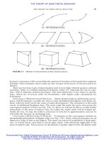
The mapping between logical and transport channels is depicted in Figure 2.15.
FACHRACH
BCCH CCCHPCCH
Logical
Channels
MAC SAPs
CPCH
(FDD only)
CTCH
DCH
CCCH DTCH/DCCH DTCH/DCCH
Transport
Channels
Uplink Downlink
BCCH Broadcast Control Channel
BCH Broadcast Channel
CCCH Common Control Channel
CCH Control Channel
CPCH Common Packet Channel
CTCH Common Traffic Channel
DCCH Dedicated Control Channel
DCH Dedicated Channel
DSCH Downlink Shared Channel
DTCH Dedicated Traffic Channel
FACH Forward Access Channel
HS-DSCH High Speed DSCH
PCCH Paging Control Channel
PCH Paging Channel
RACH Random Access Channel
BCH PCH DSCHDCH
HS-DSCH
Transport
Channels
RACH CPCH DCH
(FDD only)
BCH
PCH
FACH
DSCHDCH HS-DSCH
(y)
BCCH Broadcast Control Channel
BCH Broadcast Channel
CCCH Common Control Channel
CCH Control Channel
CPCH Common Packet Channel
CTCH Common Traffic Channel
DCCH Dedicated Control Channel
DCH Dedicated Channel
DSCH Downlink Shared Channel
DTCH Dedicated Traffic Channel
FACH Forward Access Channel
HS-DSCH High Speed DSCH
PCCH Paging Control Channel
PCH Paging Channel
RACH Random Access Channel
High-speed DSCH
Figure 2.15 Mapping between logical channels and transport channels in uplink and downlink
directions (for UTRA FDD only – i.e., without TDD channels).
2.4.2.3 Radio Link Control (RLC) Protocol
The RLC protocol provides segmentation/reassemble (Payloads Units, PU) and
retransmission services for both user (RB) and control data (Signalling RB) [6].
Each RLC instance is configured by RRC to operate in one of three modes. These are
Transparent Mode (TM), where no protocol overhead is added to higher layer data;
Unacknowledged Mode (UM), where no retransmission protocol is in use and data
delivery is not guaranteed; and Acknowledged Mode (AM), where the Automatic
Repeat reQuest (ARQ) mechanism is used for error correction. For all RLC modes,
Cyclic Redundancy Check (CRC) error detection is performed at the physical layer and
the result of the CRC is delivered to the RLC together with the actual data.
Some of the most important functions of the RLC protocol are segmentation and
reassembly of variable length higher layer PDUs into/from smaller RLC PUs; error
correction, by means of retransmission in the acknowledged da ta transfer mode; in-
sequence delivery of uppe r layer PDUs; flow control – i.e., rate control at which the
peer RLC transmitting entity may send information; protocol error detection and
recovery; Service Data Unit (SDU) discard, polling, ciphering and maintenance of
the QoS as defined by upper layers.
As shown in Table 2.1, the RLC transfer mode indicates the data transfer mode
supported by the RLC entity configured for that particular RB. The transfer mode
for a RB is the same in both uplink and downlink directions, and is determined by the
admission control in the SRNC from the RAB attributes and CN domain information.
The RLC transfer mode affects the configuration parameters of the outer-loop power
control in the RNC and the user bit rate. The quality target is not affected if TM or UM
RLC is used, while the numb er of retransmissions should be taken into account during
34 Radio Network Planning and Optimisation for UMTS
Table 2.1 RLC transfer modes for UMTS Quality of Service classes.
UMTS QoS class
a
Domain Source statistics Service type RLC transfer
descriptor mode
Conversational CS Speech CS speech TM
Unknown CS T data TM
PS Speech PS speech UM
Unknown PS RT data UM
Streaming CS Speech CS speech N/A
Unknown CS NRT data TM
PS Speech PS speech N/A
Unknown PS RT data AM or UM
b
Interactive CS N/A — N/A
PS N/A PS NRT data AM
Background CS N/A — N/A
PS N/A PS NRT data AM
a
Type of application for which the UMTS bearer service is optimised [10].
b
Transfer mode depends on the value of RAB attribute Transfer delay.
radio network planning if AM RLC is employed. The user bit rate is affected by the
transfer mode of the RLC protocol, since the length of the L2 headers is 16 bits for AM,
8 bits for UM and 0 bits for TM. Hence, the user bit rate for radio network dimension-
ing is given by the L1 bit rate reduced by the L2 header bit rate.
2.4.2.4 Packet Data Convergence Protocol
This protocol exists only in the U-plane and only for services from the Packet Switched
(PS) domain. The main PDCP functions are compression of redundant protocol control
information (e.g., TCP/IP and RTP/UDP/IP headers) at the transmitting entity and
decompression at the receiving entity; transfer of user data – i.e., receiving a
PDCP_SDU from NAS and forwarding it to the appropriate RLC entity and vice
versa; and multiplexing RBs into one RLC entity [7].
2.4.2.5 Broadcast Multicast Control Protocol
Like the PDCP, the BMC protocol exists only in the U-plane. This protocol provides a
broadcast/multi-cast transmission service on the radio interface for common user data
in TM or UM. It utilises UM RLC using the CTCH LoCH mapped onto the Forward
Access Channel (FACH). The CTCH has to be configured and the TrCH used by the
network has to be indicated to all UEs via RRC system information broadcast on the
BCH [8].
2.4.2.6 Radio Resource Control (RRC) Protocol
RRC signalling is used to control the mobility of the UE in Connected Mode; to
broadcast the information related to the NAS and AS; and to establish, reconfigure
and release RBs. The RRC protocol is further used for setting up and controlling UE
measurement-reporting criteria and the downlink outer-loop power control. Paging,
control of ciphering, initial cell selection and cell reselection are also part of RRC
connection management procedures. RRC messages carry all parameters requ ired to
set up, modify and release L2 and L1 protocol entities [9].
After power on, UEs stay in Idle Mode until a request to establish an RRC
connection is transmitted to the network. In Idle Mode the connection of the UE is
closed on all layers of the AS. In Idle Mode the UE is identifi ed by NAS identities such
as International Mobile Subscriber Identity (IMSI), Temporary Mobile Subscriber
Identity (TMSI) and Packet-TMSI. The RNC has no information about any
individual UE, and it can only address, for example, all UEs in a cell or all UEs
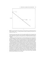
monitoring a paging oc casion [9]. The transitions between Idle Mode and UTRA
Connected Mode are shown in Figure 2.16.
The UTRA Connected Mode is entered when an RRC connection is established. The
RRC connection is defined as a point-to-point bidirectional connection between RRC
peer entities in the UE and in the UTRAN. A UE has either none or a single RRC
connection. The RRC connection establishment procedure can only be initiated by the
UE sending an RRC connection request message to the RAN. The event is triggered
either by a paging request from the network or by a request from upper layers in the
Introduction to WCDMA for UMTS 35
UE. When the RRC connection is established, the UE is assigned a Radio Network
Temporary Identity (RNTI) to be used as its own identity on CTCHs. When the
network releases the RRC connection, the signalling link and all RBs between the
UE and the UTRAN are released [9]. As depicted in Figure 2.16, the RRC states are
as follows:
. Cell_DCH. In this state the Dedicated Physical Channel (DPCH), plus eventually the
Physical Downlink Shared Channel (PDSCH), is allocated to the UE. It is entered
from Idle Mode or by establishing a DTCH from the Cell_FACH state. In this state
the terminal performs measurements according to the RRC MEASUREMENT
CONTROL message. The transition from Cell_DCH to Cell_FACH can occur via
explicit signalling – e.g., through expiration of an inactivity timer.
. Cell_FACH. In this state no DPCH is allocated to the UE; the Random Access
transport Channel (RACH) and the FACH are used for transmitting signalling
and a small amount of user data instead. The UE listens to the BCH system
information and moves to the Cell_PCH substate via explicit signalling when the
inactivity timer on the FACH expire s.
. Cell_PCH. In this state the UE location is known by the SRNC on a cell level, but it
can only be reached via a paging message. This state allows low battery consumption.
The UE may use Discontinuous Reception (DRX), reads the BCH to acquire valid
system information and moves to Cell_FACH if paged by the network or through
any uplink access – e.g., initiated by the terminal for cell reselection (cell update
procedure).
. URA_PCH. This state is similar to Cell_PCH, except that the UE executes the cell
update procedure only if the UTRAN Registration Area (URA) is changed. One cell
can belong to one or several URAs in order to avoid ping-pong effects. When the
36 Radio Network Planning and Optimisation for UMTS
GSM
Connected
Mode
GSM - UTRA intersystem handover
UTRA Connected Mode
(Allowed transitions)
Establish RRC
connection
Release RRC
connection
Initiation of
temporary
block flow
Release of
temporary
block flow
Cell reselection
Release RRC
connection
Only by paging
Establish RRC
connection
Release RRC
connection
Camping on a UTRAN cell
Idle Mode
Camping on a GSM / GPRS cell
GPRS Packet Idle Mode
GPRS Packet
Transfer Mode
URA_PCH
CELL_XXX
CELL_XXX
CELL_XXX
Establish RR
C
connection
Only by paging
Cell_XXX
URA_PCH
Cell_XXX
Cell_XXX
Figure 2.16 Radio resource control states and state transitions, including GSM Connected
Mode for PSTN/ISDN domain services and GSM/GPRS Packet Modes for IP domain services.
number of cell updates exceeds a certain limit, the UE may be moved to the
URA_PCH state via explicit signalling. The DCCH cannot be used in this state,
and any activity can be initiated by the network via a paging request on PCCH or
through uplink access by the terminal using RACH.
The understanding of RRC functions and signalling procedures is essential for radio
network tuning and optimisation. Through RRC protocol analysis, it is possible to
monitor the system information broadcast in the cell, paging messages, cell selection
and reselection pro cedures, the establishment, maintenance and release of the RRC
connection between the UE and UTRAN, the UE measurement reporting criteria
and their control, and downlink open-loop and outer-loop power control.
2.4.3 Transport Channels
In UTRAN, data generated at higher layers is carried over the air interface using
TrCHs mapped onto different physical channels. The physical layer has been
designed to support variable bit rate transport channels, to offer bandwidth-on-
demand services, and to be able to multiplex several services within the same RRC
connection into one Coded Composite Transport Channel (CCTrCH). A CCTrCH is
carried by one physical CCH and one or more physical data channels. There can be
more than one downlink CCTrCH, but only one physical CCH is transmitted on a
given connection [4].
In 3GPP all TrCHs are defined as unidirectional – i.e., uplink, downlink or relay link.
Depending on services and state, the UE can have simultaneously one or several TrCHs
in the downlink, and one or more TrCHs in the uplink.
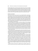
As shown in Figure 2.17, for each TrCH, at any Transmission Time Interval (TTI)
the physical layer receives from higher layers a TBS and the corresponding Transport
Format Indicator (TFI). Then L1 combines the TFI information received from
different TrCHs into one Transport Format Combination Indicator (TFCI). The
TFCI is transmit ted in the physical CCH to inform the receiver about what TrCHs
Introduction to WCDMA for UMTS 37
Transport Block
Transport Block
TFI
Physical
Control CHannel
Physical
Data CHannel
Higher Layers
Physical Layer
Physical
Control CHannel
Physical
Data CHannel
TB & Error Indication
TFI
TB & Error IndicationTransport Block
Transport Block
TFI
TB & Error Indication
TFI
TB & Error Indication
TFCI
Coding & Multiplexing
TFCI
Decoding
Demultiplexing & Decoding
TrCH 1 TrCH 2
TrCH 1 TrCH 2
Figure 2.17 Interface between higher layers and the physical layer [19].
38 Radio Network Planning and Optimisation for UMTS
are simultaneously active in the current radio frame. In the downlink, in the case of
limited TFCSs the TFCI signalling may be omitted and Blind Transport Format
Detection (BTFD) can be employed, where decoding of TrCHs can be done so as to
verify which position of the output block is matched with the CRC results [4].
Two types of TrCHs exist: dedicated channels and common channels. A common
channel is a resource divided between all users or a group of users in a cell, wher eas a
dedicated channel is by definition reserved for a single user. The connections and
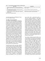
mapping between transpo rt channels and physical channels are depicted in Figure 2.18.
2.4.3.1 Dedicated Transport Channels
The only dedicated TrCH specified in 3GPP is the Dedicated Channel (DCH), which
supports variable bit rate and service multiplexing. It carries all user information
coming from higher layers, including data for the actual service (speech frames, data,
etc.) and control information (measurement control commands, UE measurement
reports, etc.). It is mapped onto the Dedicated Physical Data Channel (DPDCH).
The DPCH is characterised by closed-loop power control and fast data rate change
on a frame-by-frame basis; it can be transmitted to part of the cell and supports soft/
softer handover [4].
Physical Channels
Dedicated Physical Data Channel (DPDCH)
Dedicated Physical Control Channel (DPCCH)
Physical Random Access Channel (PRACH)
Physical Common Packet Channel (PCPCH)
Common Pilot Channel (CPICH)
Primary Common Control Physical Channel (P-CCPCH)
Secondary Common Control Physical Channel (S-CCPCH)
Synchronisation Channel (SCH)
Physical Downlink Shared Channel (PDSCH)
Acquisition Indicator Channel (AICH)
Access Preamble Acquisition Indicator Channel (AP-AICH)
Paging Indicator Channel (PICH)
CPCH Status Indicator Channel (CSICH)
Collision-Detection/Channel-Assignment Indicator Channel (CD/CA-ICH)
Transport Channels
DCH
RACH
CPCH
BCH
FACH
PCH
DSCH
HS-DSCH High Speed Physical Downlink Shared Channel (HS-PDSCH)
HS-DSCH - related Shared Control Channel (HS-SSCH)
Dedicated Physical Control Channel (uplink) for HS-DSCH (HS-DPCCH)
High-speed
Figure 2.18 Mapping of transport channels onto physical channels.
Introduction to WCDMA for UMTS 39
2.4.3.2 Common Transport Channels
The common TrCHs are a resourc e divided between all users or a group of users in a
cell (an in-band identifier is needed). They do not support soft/softer handover, but
some of them can have fast power control – for example, the Common Packet Channel
(CPCH) and Downlink Shared Channel (DSCH). As depicted in Figures 2.15 and 2.18,
the common TrCHs are as follows ([4], [2]):
. Broadcast Channel (BCH). This is used to transmit information (e.g., random
access cod es, cell access slots, cell-type transmit diversity methods, etc.) specific
to the UTRA network or to a given cell; it is mapped onto the Primary
Common Control Physical Channel (P-CCPCH), which is a downlink data
channel only.
. Forward Access Channel (FACH). This carries downlink control information to
terminals known to be located in the given cell. It is further used to transmit a
small amount of downlink packet data. There can be more than one FACH in a
cell, even multiplexed onto the same Secondary Common Control Physical Channel
(S-CCPCH). The S-CCPCH may use different offsets between the control and data
field at different symbol rates and may support slow power control.
. Paging Channel (PCH). This carries data relevant to the paging procedure. The
paging message can be transmitted in a single cell or several cells, according to the
system configuration. It is mapped onto the S-CCPCH.
. Random Access Channel (RACH). This carries uplink control information, such as a
request to set up an RRC connection. It is further used to send small amounts of
uplink packet data. It is mapped onto the Physical Random Access Channel
(PRACH).
. Uplink Common Packet Channel (CPCH). This carries uplink packet-based user
data. It supports uplink inn er-loop power control, with the aid of a downlink
Dedicated Physical Control Channel (DPCCH). Its transmission may span over
several radio frames and it is mapped onto the Physical Common Packet Channel
(PCPCH).
. Downlink Shared Channel (DSCH). This carries dedicated user data and/or control
information and can be shared in time between several users. As a pure data channel,
it is always associated with a downlink DCH. It supports the use of downlink inner-
loop power control, based on the associated uplink DPCCH. It is mapped onto the
Physical DL Shared Channel (PDSC H).
. High-speed Downlink Shared Channel (HS-DSCH). This downlink channel is
shared between UEs by allocation of individual codes from a common pool of
codes reserved for the HS-DSCH. The HS-DSCH is defined as an extension to
DCH transmission. Physical channel signalling is used for indicating to a UE
when it has been scheduled including the necessary signalling information for the
UE to decode the High-speed Physical Downlink Shared Channel (HS-PDSCH) as
well.
The common TrCHs needed for basic cell operation are RACH, FACH and PCH,
while the DSCH, CPCH and HS-DSCH may or may not be used by the operator.
2.4.3.3 Formats and Config urations
In order to describe how the mapping of TrCHs is performed and controlled by L1,
some generic definitions and terms valid for all types of TrCH are introduced in this
section. Further information can be found in [4].
. Transport Block (TB) is the basic unit exchanged between L1 and MAC for L1
processing; a TB typically corresponds to an RLC PDU or corresponding unit.
L1 adds a CRC to each TB.
. Transport Block Set (TBS) is defined as a set of TBs that are exchanged between L1
and MAC at the same time instant using the same TrCH.
. Transport Block Size is defined as the number of bits in a TB and is always fixed
within a given TBS – i.e., all TBs within a TBS are equally sized.
. Transport Block Set Size is defined as the number of bits in a TBS.
. Transmission Time Interval (TTI) is defined as the inter-arrival time of TBSs, and is
equal to the periodicity at which a TBS is transferred by the physical layer on the
radio interface. It is always a multiple of the minimum interleaving period (i.e., 10 ms,
the length of one radio frame, an exception is HS-DSCH with TTI ¼2ms as
discussed in Section 2.4.5). MAC delivers one TBS to the physical layer every
TTI.
. Transport Format (TF) is the format offered by L1 to MAC (and vice versa) for the
delivery of a TBS during a TTI on a given TrCH. It consists of one dynamic part (TB
Size, TBS Size) and one semi-static part (TTI, type of error protection– i.e., turbo
code, convolutional code or no channel coding – coding rate, static Rate Matching
parameter, size of CR C). An empty TF is defined as a TF that has a TBS size equal
to zero.
. Transport Format Set (TFS) is a set of TFs associated with a TrCH. The semi-static
parts of all TFs are the same within a TFS. TB size, TBS size and TTI define the
TrCH bit rate before L1 processing. As an example, for a DCH, assuming a TB size
of 336 bits (320 bits payload þ16 bits RLC header), a TBS size of 2 TBs per TTI, and
a TTI of 10 ms, the DCH bit rate is given by 336 Ã2/10 ¼67.2 kbps, whereas the
DCH user bit rate, which is defined as the DCH bit rate reduced by the RLC headers,
is given by 320 Ã 2/10 ¼64 kbps. Depending on the type of service carried by the
TrCH, the variable bit rate may be achieved by changing between TTIs either the
TBS size only, or both the TBS and TBS size.
. Transport Format Combination (TFC) is an authorised combination of the currently
valid TFs that can be simultaneou sly submitted to L1 on a CCTrCH of a UE –
i.e., containing one TF from each TrCH that is part of the combination. An empty
TFC is defined as a TFC that is only made up of empty TFs.
. Transport Format Combination Set (TFCS) is defined as a set of TFCs on a CCTrC H
and is produced by a proprietary algori thm in the RNC. The TFCS is what is given
to MAC by L3 for control. When mapping data onto L1, MAC chooses between the
different TFCs specified in the TFCS. MAC has only control over the dynamic part
of the TFC, since the semi-static part corresponds to the service attributes (quality,
transfer delay) set by the admission control in the RNC. The selection of TFCs can
be seen as the fast part of the RRC dedicated to MAC, close to L1. Thereby the bit
rate can be changed very quickly and with no need of L3 signalling. An example of
40 Radio Network Planning and Optimisation for UMTS
data exchange between MAC and the physical layer when two DCHs are multiplexed
in the connection is illustrated in Figure 2.19.
. Transport Format Indicator (TFI) is a label for a specific TF within a TFS. It is used
in the inter-layer communication between MAC and L1 each time a TBS is
exchanged between the two layers on a TrCH.
. Transport Format Combination Indicator (TFCI) is used to inform the receiving side
of the currently valid TFC, and hence how to decode, demultiplex and transfer the
received data to MAC on the appropriate TrCHs. MAC indicates the TFI to L1 at
each delivery of TBSs on each TrCH. L1 then builds the TFCI from the TFIs of all
parallel TrCHs of the UE, processes the TBs appropriately and appends the TFCI to
the physical control signalling (DPCCH). Through the de tection of the TFCI the
receiving side is able to identify the TFC.
The TFCS may be produced as shown in Figure 2.20 – i.e., as a Cartesian product
between TFSs of the TrCHs that are multiplexed onto a CCTrCH, each considered as a
vector. In theory every TrCH can have any TF in the TFC, but in practice only a
limited number of possible combinations are selected.
Introduction to WCDMA for UMTS 41
Transport
Block Set
(TBS)
DCH2
T T I
DCH1
T T I
T B
T B
T B
T B
Transport Block
Transport Block
Transport Block
T B
T B
Transmission Time Interval
T T I
T T I
T T I
Transport Format
(TF)
Transport Format Set
(TFS)
Transport Format Combination
(TFC)
Transport Format Combination Set
(TFCS)
Transport Format Set
(TFS)
Transport Format Combination Set
(TFCS)
Transport Format Combination
(TFC)
Transport Format
(TF)
Transport
Block Set
(TBS)
Figure 2.19 Example of data exchange between Medium Access Control and the physical layer
when two Dedicated Channels are employed.
TrCH1 TrCH2 TrCHn
Transport
format set
Transport
format
Transport Format
Combination x
Transport Format
Combination x+1
Figure 2.20 Relations of transport format, transport format set and transport format
combination.
2.4.3.4 Functions of the Physical Layer
One UE can transmit only one CCTrCH at a time, but multiple CCTrCHs can be
simultaneously received in the downlink direction. In the uplink one TFCI represents
the current TFs of all DCHs of the CCTrCH. RACHs are always mapped one-to-one
onto physical channels (PRACHs) – i.e., there is no physical layer multiplexing of
RACHs. Further, only a single CPCH of a CPCH set is mapped onto a PCPCH,
which employs a subset of the TFCs derived by the TFS of the CPCH set. A CPCH
set is characterised by a set-specific scrambling code for access preamble and collision
detection, and is assigned to the terminal when a service is configured for CPCH
transmission [4].
In the downlink the mapping between DCHs and physical channel data streams
works in the same way as in the uplink direction. The current configuration of the
coding and multiplexing unit is either signalled (TFCI) to the UE, or optionally
blindly (BTFD) detected. Each CCTrCH has only zero or one corresponding TFCI
mapped (each 10 ms radio frame) on the same DPCCH used in the connection. A PCH
and one or several FACHs can be encod ed and multiplexed together forming a
CCTrCH, one TFCI indicates the TFs used on each FACH and PCH carried by the
same S-C CPCH. The PCH is always associated with the Paging Indicator Channel
(PICH), which is used to trigger off the UE reception of S-CCPCH where the PCH
is mapped. A FACH or a PCH can also be individually mapped onto a separate
physical channel. The BCH is always mapped onto the P-CCPCH, with no multiplexing
with other TrCHs [4].
The main functions of the physical layer are Forward Error Correction (FEC)
encoding and decoding of TrCHs, measurements and indication to higher layers
(e.g., BER, SIR, interference power, transmission power, etc.), macro-diversity
distribution/combining and softer handover execution, error detection on TrCH s
(CRC), multiplexing of transport channels and demultiplexing of CCTrCHs, rate
matching, mapping of CCTrCHs onto physical channels, modulation/ demodulation
and spreading/despreading of physical channels, frequency and time (chip, bit, slot,
frame) synchronisation, closed-loop (inner-loop) power control, power weighting,
combining of physical channels and RF pro cessing.
The multiplexing and channel coding chain is depict ed in Figures 2.21 and 2.22 for
the uplink and downlink direction, respectively. As shown in these figures, data arrive
at the coding/multiplexing unit in the form of TBSs once every TTI. The TTI is TrCH-
specific from the set (10 ms, 20 ms, 40 ms, 80 ms) [12].
Error detection is provided on transport blocks through a CRC. The CRC length is
determined by the admission control in the RNC and can be 24, 16, 12, 8 or 0 bits [12].
Regardless of the result of the CRC, all TBs are delivered to L2 along with the
associated error indications. This estimation is then used as quality information for
UL macro-diversity selection/combining in the RNC, and may also be used directly as
an error indication to L2 for each erroneous TB in TM, UM and AM RLC, provided
that RLC PDUs are mapped one-to-one onto TBs.
Depending on whether the TB fits in the available code block size (channel coding
method), the TBs in a TTI are either concatenated or segmented to coding blocks of
suitable size.
42 Radio Network Planning and Optimisation for UMTS
Channel coding and radio frame equalisation is performed on the coding blocks after
the concatenation or segmentation operation. Only the channel-coding schemes
reported in Table 2.2 can be applied to TrCHs – i.e., either convolutional coding,
turbo coding or no coding (no limitation to coding block size).
Introduction to WCDMA for UMTS 43
Rate
matching
Physical channel
segmentation
Radio frame segmentation
2
nd
Interleaving / RF
Channel coding
Rate matching
CRC attachment / TB
Radio frame equalisation
1
st
Interleaving / TTI
TrCH Multiplexing
CCTrCH
PhCH #1
PhCH #2
TrCH
#1
MAC and
higher layers
Spreading/Scrambling
and Modulation
TrBk concatenation /
Code block segmentation
Physical channel mapping
Figure 2.21 Uplink multiplexing and channel coding chain.
Rate
matching
Physical channel
segmentation
1st interleaving / TTI
2
nd
Interleaving / RF
Channel coding
Rate matching
CRC attachment / TB
Radio frame segmentation
1st insertion of DTX
indication
TrCH Multiplexing
CCTrCH
PhCH #1
PhCH #2
TrCH
#1
Spreading/Scrambling
and Modulation
TrBk concatenation /
Code block segmentation
Physical channel mapping
2nd insertion of DTX
indication
MAC and
higher layers
Figure 2.22 Downlink multiplexing and channel coding chain.
Table 2.2 Transport Channel coding schemes.
Type of TrCH Coding scheme Coding rate
BCH, PCH, RACH Convolutional coding 1/2
CPCH, DCH, DSCH, FACH Convolutional coding 1/3, 1/2
Turbo coding 1/3
No coding
44 Radio Network Planning and Optimisation for UMTS
Convolutional coding is typically used with relative low data rates – e.g., the BTFD
using the Viterbi decoder is much faster than turbo coding – whereas turbo coding is
applied for higher data rates and brings performance benefits when a large enough
block size is achieved for a significant interleaving effect [19]. For example, the
Adaptive Multi Rate (AMR) speech service (coordinated TrCHs, multiplexed in the
FP) uses Unequal Error Protection (UEP): class A bits, strong protection (1/3 convolu-
tional coding and 12 bits CRC); class B bits, less protected (1/3 convolutional coding);
and class C bits, least protection (1/2 convolutional coding).
The function of radio frame equalisation (padding) is to ensure that data arriving
after channel coding can be divided into blocks of equal length when transmitted over
more than a single 10 ms radio frame. Such radio frame equalisation is only performed
in the uplink, because in the downlink the rate matching output block length is already
produced in blocks of equal size per frame.
The first interleaving (or the first radio frame interleaving) is used when the delay
budget allows more than 10 ms of interleaving period. The first interleaving period is
related to the TTI.
The rate matching procedure is used to match the number of bits to be transmitted to
the number available on a single frame (DPCH), either by puncturing or by repetition.
The amount of puncturing or repetition depends on the particular service combination
and their QoS requirements.
Rate matching takes into account the number of bits of all TrCHs active in that
frame. The admission control located in the RNC provides a semi-static parameter, the
rate matching attribute, to control the relative rate matching between different TrCHs.
The rate matching attribute is used to calculate the rate matc hing value when multi-
plexing several TrCHs for the same fram e. With the aid of the rate matching attribute
and TFCI, the receiver can back-calculate the rate matching parameters used and
perform the inverse operation. By adjusting the rate matching attribute, admission
control of the RNC fine-tunes the quality of different services in order to reach an
equal or nearly equal symbol power-level requirement for all services.
Variable rate handling is performed after TrCH multiplexing for matching the total
instantaneous rate of the multiplexed TrCHs to the channel bit rate of the DPDCH
(when the TBSs do not contain the maximum number of DPDCH bits). The number of
bits on a TrCH can vary between different TTIs.
In the downlink, transmission is interrupted if the number of bits is less than the
maximum allowed by the DPDCH. As shown in Figure 2.23(a), a fixed position TrCH
always uses the same symbols in the DPCH. If the transmission rate is below the
maximum, Discontinuous Transmission (DTX) indica tion is then used for those
symbols. The different TrCHs do not have a dynamic impact on the rate matching
values applied for the other channel, and all TrCHs can use the maximum bit rate
simultaneously (the space taken always depends on the maximum TF of the TFS). A
fixed position TrCH allows easier blind detection. If TrCH positions were flexible when
mapped onto the physical channel, as shown in Figure 2.23(b), the channel bits not
being used by one service might be used by another. Blind detection is possible (for low
data rates an d for a few possibly higher data rates) but is not required by the specifica-
tions [19].
Introduction to WCDMA for UMTS 45
In the uplink, bits are repeated or punctured to ensure that the total bit rate after
TrCH multiplexing is identical to the total channel bit rate of the allocated DPCHs.
Rate matching is performed in a more dynamic way and may vary on a frame-by-frame
basis.
Multicode transmission is employed when the total bit rate to be transmitted on a
CCTrCH exceeds the maximum bit rate of the DPCH. Multicode transmission depends
on the multi-code capabilities of the UE and Node B, and consists of several parallel
DPDCHs transmitted for one CCTrCH using the same Spreading Factor (SF):
. In the downlink, if several CCTrCHs are employed for one UE, each CCTrCH can
have a different spreading factor, but only one DPCCH is used for them in the
connection.
. In the uplink, the UE can use only one CCTrCH simultaneously. M ulticode
operation is possible if the maximum allowed amount of puncturing has already
been applied. For the different codes it is mandatory for the terminal to use
SF ¼4. Up to six parallel DPDCHs and only one DPCCH per connection can be
transmitted.
The second interleaving is also called intra-frame interleaving (10 ms radio frame
interleaving). It consists of block inter-column permutations, separately applied for
each physical channel (if more than a single code channel is trans mitted).
2.4.4 Physical Channels and Mapping of Transport Channels (FDD)
In this section the dedicated physical channel structure is described. Further explana-
tion can be found in [11]. A physical channel is identified by a specific carrier frequency,
scrambling code, channelisation code (opti onal), duration and, on the uplink, relative
phase (0 or /2). In UMTS the transmission of a physical channel in normal mode is
continuous, but in compressed mode it is interrupted to allow the UE to monitor cells
on other FDD frequencies and those from other radio access technologies, such as
GSM.
TrCH BTrCH A TPC
DL DPCH slot
TFCI
DTX
TFCI TrCH A TPC TrCH B
Pilot
Pilot
(a)
TrCH BTrCH A TPC
DL DPCH slot
TFCI
TFCI TrCH A TPC TrCH B
Pilot
Pilot
TrCH B
(b)
Figure 2.23 Example of (a) fixed position and (b) flexible position Transport Channels.
2.4.4.1 Dedicated Physical Channel Structure
The dedicated physical channel structure is depicted in Figure 2.24. In this model each
2-bit pair represents an I/Q pair of Quaternary Phase Shift Keying (QPSK) modulation
(symbol). As shown in the figure, the frame structure consists of a sequence of radio
frames, one radio frame corresponding to 15 slots (10 ms or 38400 chips) and one slot
corresponding to 2560 chips (0.667 ms), which equals one power control period.
2.4.4.2 Dedicated Uplink Physical Channel
The dedicated uplink physical channel structure for one power control period is shown
in Figure 2.24. The dedicated higher layer information, including user data and
signalling, is carried by the uplink DPDCH, and the control information generated
at L1 is mapped onto the uplink DPCCH. The DPCCH comprises pre-defined Pilot
symbols (used for channel estimation and coherent detection/averaging), power control
commands, Feedback Information (FBI) for closed-loop mode transmit diversity and
Site Selection Diversity Technique (SSDT), and optionally a TFCI. There can be zero,
one or several uplink DPDCHs on each radio link, but only one uplink DPCCH is
transmitted. DPDCH(s) and DPCCH are I/Q-code-multiplexed with complex
scrambling. Further, as shown in Table 2.3, the uplink DPDCH can have a
spreading factor from 256 (15 ksps) down to 4 (960 ksps), whereas the uplink
DPCCH is always transmitted with a spreading factor of 256 (15 ksps). Table 2.3
also shows the uplink physical channel parameters for multiplexing of data, speech
and Signalling Radio Bearer (SRB) [11].
Admission control in the RNC produces the TFCS and estimates the minimum
allowed SF. As already pointed out, in the uplink for variable rate handling the
DPDCH bit rate (spreading factor) may vary frame by frame. The parallel transmission
of DPDCH and DPCCH, as depicted in Figure 2.25, allows continuous transmission
regardless of the bit rate and data transmission (DTX ). Audible interference to other
equipment is then reduced without affecting spectral efficiency.
46 Radio Network Planning and Optimisation for UMTS
Radio frame (10 ms)
#1#0 #71
#0 #1 #14
Slot (0.667 ms)
Data
Pilot TFCI TPCFBI
TPC TFCI PilotDataData
DPCCH
DPDCH
Uplink
Structure
Downlink
Structure
I/Q code multiplexed with
complex scrambling
Time multiplexed with complex scrambling
DPDCH DPCCH DPCCHDPDCH
Figure 2.24 Structure of the dedicated physical channels, in the uplink and downlink directions.
Introduction to WCDMA for UMTS 47
Table 2.3 Uplink Dedicated Physical Data Channel symbol rates and examples of services
multiplexing.
SF Channel User bit rate Example of Transport format
symbol rate services multiplexing (semi-static part)
[ksps]
a
[kbps]
256 15 3.4 Standalone mapping of SRB (TTI 40 ms,
DCCH 3.4 kbps CC coding rate 1/3)
128 30 — — —
64 60 12.2 þ3.4 AMR speech 12.2 kbps, AMR (TTI 20 ms,
DCCH 3.4 kbps CC 1/3 for TrCH dA
and dB; CC 1/2 for
TrCH dC) and SRB
(as above)
32 120 28.8 þ3.4 Modem 28.8 kbps, CS data (TTI 40 ms,
DCCH 3.4 kbps turbo coding 1/3) and
SRB (as above)
16 240 (12.2)
b
þ64 þ3.4 (AMR speech 12.2 kbps), Packet data 64 kbps
packet data 64 kbps, (TTI 20 ms, turbo
DCCH 3.4 kbps coding 1/3), AMR and
SRB (as above)
16 240 64 þ3.4 ISDN 64 kbps, CS data (TTI 40 ms,
DCCH 3.4 kbps turbo coding 1/3) and
SRB (as above)
16 240 57.6 þ3.4 Fax 57.6 kbps, CS data (TTI 40 ms,
DCCH 3.4 kbps turbo coding 1/3) and
SRB (as above)
8 480 (12.2) þ128 þ3.4 (AMR speech 12.2 kbps), Packet data 128 kbps
packet data 128 kbps, (TTI 20 ms, turbo
DCCH 3.4 kbps coding 1/3), AMR and
SRB (as above)
8 480 (12.2) þ144 þ3.4 (AMR speech 12.2 kbps), Packet data 144 kbps
packet data 144 kbps, (TTI 20 ms, turbo
DCCH 3.4 kbps coding 1/3), AMR and
SRB (as above)
4 960 (12.2) þ384 þ3.4 (AMR speech 12.2 kbps), Packet data 384 kbps
packet data 384 kbps, (TTI 20 ms, turbo
DCCH 3.4 kbps coding 1/3), AMR and
SRB (as above)
a
In the uplink 1 symbol ¼1 bit.
b
AMR speech when shown in brackets does not affect the spreading factor.
2.4.4.3 Dedicated Downlink Physical Channel
In the downlink the downlink DPCH consists of a downlink DPDCH and a downlink
DPCCH time-multiplexed with complex scrambling. Therefore the dedicated data
generated at higher layers carried on DPDCH are time-multiplexed with pilot bits,
TPC commands and TFCI bits (optional) generated by the physical layer. As
pointed out in Section 2.4.3.4, the DPCH may or may not include the TFCI; if the
TFCI bits are not transmitted, DTX is used in the corresponding field. The dedicated
downlink physical channel structure for one power control period is shown in Figure
2.24. The I/Q branches ha ve equal power and the SFs range from 512 (7.5 ksps) down
to 4 (960 ksps) [11]. Examples of services multiplexing are shown in Table 2.4.
As introduced in Section 2.4.3.4, when the total bit rate to be transmitted on one
downlink CCTrCH exceeds the maximum bit rate of the downlink physical channel,
multi-code transmission is employed and several parallel code channels are transmitted
for one CCTrCH using the same spreading factor. Different spreading factors can be
used when several CCTrCHs are mapped onto different DPCHs transmitted to the
same UE. As illustrated in Figure 2.26, the L1 control information is only transmitted
on the first DPCH and the transmission is interrupted during the corresponding time
period of the additional DPCHs [11].
2.4.4.4 Common Uplink Physical Channels
The common uplink physical channels are the PRACH and the PCPCH, which are used
to carry RACH and CPCH, respectively. The RACH is transmitted using open-loop
power control. The CPCH is transmitted using inner-loop power control and is alw ays
associated with a downlink DPCCH carrying power control commands [11].
Physical Random Access Channel (PRACH)
Random access transmission is based on a slotted ALOHA approach with fast
acquisition indication. There are 15 access slots per two frames spaced 5120 chips
apart, as shown in Figure 2.27. Information concerning which access slots are
available in the cell for random access transmission is broadcast on the BCH [11].
Random access transmission consists of one or several preambles and a message part.
The structure of the RACH transmission is illustrated in Figure 2.28. The preamble
48 Radio Network Planning and Optimisation for UMTS
DPCCH
DPDCH
Lower bit rate
Higher bit rate
Medium bit rate
10 ms frame 10 ms frame 10 ms frame
Power
Transmission
power
Figure 2.25 Parallel transmission of Dedicated Physical Data Channel and Dedicated Physical
Control Channel.
Introduction to WCDMA for UMTS 49
Table 2.4 Downlink Dedicated Physical Data Channel symbol rates and examples of services
multiplexing.
SF Channel User bit rate Example of services Transport format
symbol rate multiplexing (semi-static part)
[ksps]
a
[kbps] (RBs and SRB)
512 7.5 — — —
256 15 3.4 Standalone mapping of SRB (TTI 40 ms,
DCCH 3.4 kbps CC coding rate 1/3)
128 30 12.2 þ3.4 AMR speech 12.2 kbps, AMR (TTI 20 ms,
DCCH 3.4 kbps CC 1/3 for TrCH dA
and dB; CC 1/2 for
TrCH dC) and SRB
(as above)
64 60 28.8 þ3.4 Modem 28.8 kbps, CS data (TTI 40 ms,
DCCH 3.4 kbps turbo coding 1/3) and
SRB (as above)
32 120 57.6 þ3.4 Fax 57.6 kbps, CS data (TTI 40 ms,
DCCH 3.4 kbps turbo coding 1/3) and
SRB (as above)
32 120 (12.2)
b
þ64 þ3.4 (AMR speech 12.2 kbps), Packet data 64 kbps
packet data 64 kbps, (TTI 20 ms, turbo
DCCH 3.4 kbps coding 1/3), AMR and
SRB (as above)
32 120 64 þ3.4 ISDN 64 kbps, CS data (TTI 40 ms,
DCCH 3.4 kbps turbo coding 1/3), SRB
(as above)
16 240 (12.2) þ128 þ3.4 (AMR speech 12.2 kbps), Packet data 128 kbps
packet data 128 kbps, (TTI 20 ms, turbo
DCCH 3.4 kbps coding 1/3), AMR and
SRB (as above)
16 240 (12.2) þ144 þ3.4 (AMR speech 12.2 kbps), Packet data 144 kbps
packet data 144 kbps, (TTI 20 ms, turbo
DCCH 3.4 kbps coding 1/3), AMR and
SRB (as above)
8 480
c
(12.2) þ384 þ3.4 (AMR speech 12.2 kbps), Packet data 384 kbps
packet data 384 kbps, (TTI 20 ms, turbo
DCCH 3.4 kbps coding 1/3), AMR and
SRB (as above)
4 960 — — —
a
In the downlink 1 symbol ¼2 bits.
b
AMR speech when shown in brackets does not affect the spreading factor.
c
Or multicode 3 Ã 240 ksps.
50 Radio Network Planning and Optimisation for UMTS
Transmission
Power
One Slot (2560 chips)
Data
TPC TFCI
Transmission
Power
Transmission
Power
Physical Channel 1
Physical Channel 2
Physical Channel N
Data
Pilot
Data Data
Data Data
DPDCHDPDCH DPCCH DPCCH
Figure 2.26 Downlink slot format in case of multicode transmission, showing N parallel
physical channels.
Radio frame (10 ms)
Radio frame (10 ms)
Random Access Transmission
Access Slot #7
Access Slot #8
Access Slot #1
Access Slot #0
#0 #1 #2 #3 #4 #5 #6 # 7 #8 #9
#10 #11 #12 #13 #14
Access slot #14
5120 chips
Figure 2.27 Random Access Channel access slot numbers and spacing between consecutive
access slots.
AICH Access Slot
Acquisition
Indicator
Rx at UE
AICH access slots
Preamble
Power Ramp Step
Preamble
Message part
Tx at UE
PRACH access slots
P
p-m
Preamble Retrans Max
Figure 2.28 Physical Random Access Channel ramping and message transmission.
comprises 4096 chips, being made up of 256 repetitions of a signature of length 16 chips
(256 Ã16 ¼4096) [14].
The slot structure of the PRACH message is illustrated in Figure 2.29. It consists of
two parts, a data part where the RACH transport channel is mapped and a control part
where the L1 control information is carried. The data and control parts are transmitted
in parallel. The SFs of the data part are 256, 128, 64 and 32. The control part consists of
Pilot and TFCI bits and has a spreadi ng factor of 256. The TFCI field indicates the TF
of the RACH mapped onto the data part of the radio frame and is repeated in the
second radio frame if the message part lasts for 20 ms [11].
A RACH sub-channel is defined as a subset of the total set of the uplink access slots.
The 12 RACH sub-channels available for each cell can be found in [14].
Each cell is configured during radio network planning setting the preamble
scrambling code, the message length in time (either 10 or 20 ms), the Acquisition
Indicator Channel (AICH) Transmission Timing parameter (0 or 1, for setting the
preamble-to-AI distance), the set of available signatures and the set of available
RACH sub-channels for each Access Service Class (ASC).
2
As depicted in Figure
2.28, other essential parameters that need to be set during radio network planning
are the power ramping factor (‘Power Ramp Step’), the maximum number of
preamble retransmissions (‘Preamble Retrans Max’), and the power offset between
the power of the last transmitted preamble and the control part of the PRACH
message (Power offset P
p-m
¼ P
message-control
À P
preamble
). The UE receives these data
from the system information broadcast on the BCH, which may be updated by the
RNC before any physical random access procedure is initiated. The physical random
access procedure is illustrated in Figure 2.28 and may be summarised as follows (more
information can be found in [14]):
. The UE derives the available uplink access slots (in the next full access slot set) from
the set of available RACH sub-channels within the given ASC.
. The UE randomly selects one access slot from among those previously determined
Introduction to WCDMA for UMTS 51
TFCIPilot
Data
T
slot
= 2560 chips
Data
Control
Figure 2.29 Structure of the random access message part radio frame.
2
In order to provide different priorities of RACH usage when the RRC connection is set up,
PRACH resources (access slots and preamble signatures) can be divided between eight different
ASCs numbered from 0 (highest priority, used in case of emergency call or for reasons with
equivalent priority) to 7 (lowest priority). The PRACH partitioning and the one-to-one corre-
spondence (mapping) between the terminal Access Class (AC) and ASC are specified in [9]. If the
UE is a member of several ACs, then it selects the ASC for the highest AC number. An ASC
defines a certain partition of the PRACH resources and is always associated with a persistence
value computed by the terminal as a function of a dynamic persistence level (1–8) and a
persistence-scaling factor (seven values, from 0 to 1 for ASC 2-7) set during radio network
planning.
and randomly selects a signature from the set of available signatures within the given
ASC.
. The UE transmits the first preamble using the selected uplink access slot, signature
and preamble transmission power, calculated as explained in Section 4.2.1.1.
. If no positive or negative Acquisition Indicator (AI 6¼þ1 nor À1) corresponding to
the selected signature is detected in the downlink access slot corresponding to the
selected uplink access slot, then the terminal selects the next available access slot in
the set of available RACH sub-channels within the given ASC, randomly selects a
new signature from the set of available signatures within the given ASC and increases
the preamble power by DP
0
¼Power Ramp Step [dB].
. If the number of retransmissions exceeds the ‘Preamble Retrans Max’ value or if a
negative AI corresponding to the selected signature is detected, then the UE exits the
physical random access procedure. Otherwise, the UE transmits the random access
message three or four uplink access slots after the uplink access slot of the last
transmitted preamble, depending on the AICH transmission-timing parameter. The
transmission power of the control part of the random access message is P
p-m
[dB]
higher than the power of the last transmitted preamble. The transmission power of
the data part of the rando m access message is set according to the corresponding gain
factor. The meaning of the gain factors is further explained in Se ction 2.4.7.
Physical Common Packet Channel (PCPCH)
The PCPCH is used to carry the CPCH TrCH. Briefly, CPCH is like RACH with fast
power control and longer allocation time, and with the possibility of using higher bit
rates to transfer larger amounts of data with a more controlled access method.
CPCH is intended to carry packet switched user data in the uplink direction. One of
its main advantages is a short access delay with a high bit rate, which makes it especially
suitable for bursty data. Compared with DCH, CPCH is a good alternative, because it
can be better multiplexed in the time domain and it can also better adapt to data rate
changes. On the other hand, CPCH may also degrade capacity, owing to its lack of soft
handover. For longer uplink packet data transmission, it is better to use DCH. The lack
of soft handover makes CPCH coverage inferior when compared with DCH. Since
CPCH uses fast power control, it gives a better spectrum efficiency and thus a better
capacity than RACH , which is not power-controlled. The effect of this advantage on
overall network capacit y depends on the extent to which these channels are used for
data transmission.
If CPCH is used, it should be possible to use high bit rates. This means that CPCH
can contribute to uplink noise rise. In that case, CPCH load should be taken into
account in radio network planning.
CPCH transmission is based on the Collision Detection–Digital Sense Multiple
Access (CD-DSMA) approach with fast AI. The UE can start transmission at the
beginning of a number of well-defined time intervals. Access slot timing and
structure are identical to those of RACH.
The structure of CPCH access transmission is shown in Figure 2.30. It consists of one
or several Access Preambles (APs), one Collision Detection (CD) preamble, a PCPC H
power control preamble and a message of variable length.
The structure of the PCPCH data part is shown in Figure 2.31.
52 Radio Network Planning and Optimisation for UMTS
For the data part of the PCPCH message part, the permitted spreading factors may
vary from 4 to 256, whereas the control part of the PCPCH message has a fixed
spreading factor of 256. The spreading factor of the downlink DPCCH is fixed at
512. The maximum length of the message part – i.e., the maximum CPCH allocation
time – can vary between 20 and 640 ms. It is a higher layer parameter and can be set by
radio network planning as well as channel configurations including allowed spreading
factors and bit rates.
The PCPCH AP part, the PCPCH collision detection/channel assignment preamble
part and the PCPCH power control preamble part are UL physical signals associated
with the PCPCH, which also carries CPCH transport channel data. A set of downlink
physical channels are needed for the CPCH access procedure:
. CPCH Status Indicator Channel (CSICH);
. Access Preamble Acquisition Indicator Channel (AP-AICH);
. Collision Detection/Channel Assignment Indicator Channel (CD/CA-ICH).
Based on the availability information of each PCPCH that the CSICH indicates, the
UE initiates the CPCH access procedure on an unus ed channel. A CSICH is always
associated with an AP-AICH and uses the same channelisation code. The AP-AICH is
used to carry access preamble acquisition indicators of the CPCH to the UE. The
AP-AICH and the AICH are identical and may use the same channelisation code.
The CD/CA-ICH is used to carry collision detection and channel assignment
indicators to the UE.
The CPCH access procedure is fairly similar to the RACH access procedure. The
main difference is the additional collision de tection procedure. The extra step includes
Introduction to WCDMA for UMTS 53
AP
AP CD
AP-AICH CD/CA-ICH
DPCCH (DL)
PCPCH (UL)
power control, pilot and CPCH control commands
Uplink
Downlink
power
control
preamble
information and control data
T
0
0 or 8 time slots
Figure 2.30 Structure of the Common Packet Channel access transmission.
Pilot
Data
TFCI
T
slot
= 2560 chips
FBI TPC
Data
Control
Figure 2.31 Structure of the Physical Common Packet Channel message part radio frame.
collision detection preamble transmission on PCPCH in the uplink, and transmission of
collision detection and channel assignment on the CD/CA-ICH in the downlink.
Each cell is configured during radio network planning setting the AP and CD
preamble scrambling codes, signature sets and sub-channels defining the available
access slots, AP-AICH and CD/CA-ICH preamble channelisation codes, CPCH
scrambling code and downlink DPCCH channelisation cod e. Other essential
parameters that need to be set during radio network planning are the power ramp-
up, access and timing parameters. The UE receives these data from the system informa-
tion broadcast on the BCH. The CPCH access procedure may be summarised as
follows; more information can be found in [14]:
. The UE selects a CPCH transport channel from the available CPCH set in the
CSICH chan nel and builds a TB for the next TTI. The TB is sent to the physical
layer, and the initial power value is set. The AP retransmission counter is set to its
maximum value.
. The UE randomly selects a CPCH AP signatu re from the signature set of the CPCH
channel and one available access slot.
. The UE transmits an AP.
. If the UE does not detect any AI corresponding to the selected signature in the
downlink access slot corresponding to the selected upl ink access slot, the UE
selects the next available access slot and retransmits the AP.
. If the UE detects a negative acquisition indication in the AP-AICH in the
corresponding slot with the selected signature, it ab orts access.
. When the UE detects a positive acquisition indication in the AP-AICH, the
contention segment starts. The UE randomly selects a CD signature and a CD
access slot sub-channel, then transmits the CD preamble.
. If the UE does not receive the CD-AICH in the designated slot with the correspond-
ing signature, it aborts access.
. If the UE receives the CD-AICH in the correct timeslot with the matching signature,
it transmits the PC preamble; immediately thereafter data transmission starts.
The collision in the CPCH means that two UEs have selected the same access channel
and preamble at the same time. After that it is unlikely, but not impossible, that they
select again the same CD preamble. The Node B responds to only one CD preambl e –
i.e., the strongest. Although the channels are defined since Release ’99 in 3GPP, another
method High-speed Uplink Packet Access (HSUPA) is coming with Release 6 in 3GPP
[37] as a more efficient and easy way to implement high bit rate packet data traffic access
in the uplink.
2.4.4.5 Common Downlink Physical Channels
Most of the common downlink physical channels are used for transmitting signalling
messages generated by the entity above the physical layer. The other common physical
channels requir ed for system operation are the physical layer control channels and the
PDSCH, which is used for transmitting high peak rate data with a low activity cycle in
the downlink like the HS-PDSCH .
54 Radio Network Planning and Optimisation for UMTS
Common Pilot Channel (CPICH)
There are two types of common pilot channels, the Primary and the Secondary CPICH.
They are transmitted at a fixed rate (15 kbps, SF ¼256) and carry only a pre-defined
symbol sequence. The slot structure for the common pilot channels is illustrated in
Figure 2.32.
The Primary Common Pilot Channel (P-CPICH) is characterised by a fixed
channelisation code (C
ch;256;0
) and is always scrambled using a primary scrambling
code; see Section 2.4.7 for further explanation. There is one P-CPICH per cell and
it is broadcast over the entire cell. The P-CPICH is the phase reference for the
Synchronisation Channel (SCH), Primary Common Control Physical Channel
(P-CCPCH), AICH, PICH, DL DPCCH for CPCH, S-CCPCH and by default for
the DL DPCH [11].
The Secondary Common Pilot Channel (S-CPICH) is characterised by an arbitrary
channelisation code with a spreading factor of 256, scrambled by either a primary or a
secondary scrambling code. In a cell there may be no, one or several S-CPICHs. Each
S-CPICH may be transmitted over the entire cell or over only a part of the cell [11].
If the P-CPICH is not used as a phase reference for the downlink DPCH, the UE is
informed about it by the network. In that case for channel estimation it may use the
S-CPICH or the pilot bits on the DL DPCCH [9].
Primary Common Control Physical Channel (P-CCPCH)
The P-CCPCH is a fixed rate (15 ksps, SF ¼256) DL physical channel used to carry the
BCH. It is a pure data channel characterised by a fixed channelisation code (C
ch;256;1
).
The P-CCPCH is broadcast over the entire cell and is not transmitted during the first
Introduction to WCDMA for UMTS 55
#0
Radio frame (10 ms)
Slot (2560 chips)
20 bits
S-CCPCH
Any CPICH
256 chips
P-CCPCH
#1
#0 #1 #14
Pre-defined pilot sequence
Data only (18 bits)(Tx OFF)
20 bits
PilotsDataTFCI
20 x 2
k
bits (k = 0, …, 6)
15 ksps; SF = 256
C
ch,256,0
(P-CPICH
15 ksps; SF = 256
C
ch,256,1
15-960 ksps;
SF = 256-4
)
Figure 2.32 Slot structure of the Common Pilot Channel, Primary Common Control Physical
Channel and Secondary Common Control Physical Channel.
256 chips of each slot, where the Primary SCH and the Secondary SCH are transmitted
instead (see Figure 2.32) [11].
Secondary Common Control Physical Channel (S-CCPCH)
The S-CCPCH is used to carry the FACH and PCH, which can be mapped onto the
same S-CCPCH (same frame) or onto separate S-CCPCHs. The slot structure for the
S-CCPCH is depicted in Figure 2.32. The S-CCPCH spreading factor ranges from 256
(15 ksps) down to 4 (960 ksps). Fast power control is not allowed, but the power of the
S-CCPCH carrying only the FACH may be slowly power-controlled by the RNC. The
S-CCPCH supports multiple transport format combinations (variable rate) using TFCI
and it is on air only when there are data to transmit [11].
Synchronisation Channel (SCH)
The SCH is a pure physical channel used in the cell search procedure. It consists of two
sub-channels transmitted in parallel, the Primary SCH and the Secondary SCH [11].
The Primary SCH consists of a modulated code of length 256 chips, the Primary
Synchronisation Code (PSC), denoted C
p
in Figure 2.33. The PSC is transmitted once
every slot; it allows downlink slot synchronisation in the cell and is identical in every
cell of the system.
Primary SCH
Secondary SCH
256 chips
2560 chips
SCH radio frame (10 ms)
aC
p
Slot #0 Slot #1 Slot #14
aC
p
aC
p
aC
s
i,0
aC
s
i ,1
aC
s
i,14
Same code in each
slot for every cell in
the network; for slot
synchronisation
Same code in each
slot for every cell in
the network; for slot
synchronisation
64 possible code
sequences; for frame
synchronisation and
scrambling code group
identification
64 possible code
sequences; for frame
synchronisation and
scrambling code group
identification
Figure 2.33 Structure of Synchronisation Channel (SCH); the symbol a indicates the presence or
absence of Space Time Transmit Diversity (STTD) on the P-CCPCH; C
p
and C
i;k
s
are the Primary
and Secondary Synchronisation Codes (PSC and SSC), respectively.
The Secondary SCH consists of a sequence of repeatedly transmitted modulated
codes of length 256 chips, the Secondary Synchronisation Codes (SSCs), denoted C
i;k
s
in Figure 2.33, where i ¼ 0; 1; ; 63 is the number of the scrambling code group, and
k ¼ 0; 1; ; 14 is the slot number. This sequence permits downlink frame synchroni sa-
tion and indicates from which of the code groups the cell got assigned its downlink
primary scrambling code. This narrows down the search for the primary scrambling
code to eight codes.
Physical Downlink Shared Channel (PDSCH)
The PDSCH is used to carry the DSCH TrCH. The DSCH offers fast power control
and effective scheduling possibilities, but no soft handover.
The DSCH is targeted to transfer bursty non-real time packet switched data. The
basic idea of the DSCH is to share a single downlink physical channel – i.e., orthogonal
downlink channelisation code – between several users. DSCH scheduling can be
56 Radio Network Planning and Optimisation for UMTS
considered as multiplexing of several DTCH logical channels of the same or different
UEs to the DSCH transport channel in time division.
Faster allocation of the PDSCH will use potential capacity better than slower
allocation of the DCH. As a result, QoS differentiation and prioritisation can be
utilised effectively. From coverage point of view, the DSCH is not advantageous due
to its lack of soft handover. The DSCH can be planned to be used over the whole cell,
when hard handover is acceptable, or it can be planned not to cover the whole cell, in
which case channel- type switching from the DSCH to the DCH is required when the
DSCH coverage ends.
When data are transmitted with low activity on the DCH and inactive periods occur,
a dedicated downlink channelisation code is still reserved, which may cause codes to
run out. Since one code is shared between several users in the case of the DSCH, other
users can take advantage of a user’s inactive periods. Thus, downlink channelisation
code usage is more efficient with the DSCH than with the DCH. Code blocking is less
likely when the DSCH is used, and the capacity can be higher.
A PDSCH, which is used to carry the DSCH, corresponds to a channelisation code
below or at a PDSCH root channelisation code. Figure 2.34 shows the PDSCH code
resource allocation from the OVSF code tree.
A PDSCH is allocated on a radio frame basis to a single UE. Within one radio frame,
the RAN may allocate different PDSCHs under the same PDSCH root channelisation
code to different UEs based on code multiplexing. Within the same radio frame,
multiple parallel PDSCHs with the same spreading factor may be allocated to a
single UE. For the PDSCH the allowed permitted spreading factor may vary from 4
to 256.
For each radio frame, ea ch PDSCH is associated with one downlink DPCH in order
to support fast power control and to inform the UE of the arrival of data on the DSCH.
The PDSCH and associated DPCH do not necessarily have the same spreading factor
and are not necessarily frame-aligned. All relevant physical layer control is transmitted
on the DPCCH part of the associated DPCH. The PDSCH itself does not carry any
Introduction to WCDMA for UMTS 57
SF = n/4
SF = n/2
SF = n
SF = 2n
SF = 4n
SF = 8n
SF = 16n
SF = n/8
= Channelisation code
PDSCH root channelisation code
. . .
. . .
. . .
. . . . . .
. . .
reserved
subtree
higher bit rate
lower SF
lower bit rate
higher SF
Figure 2.34 Physical Downlink Shared Channel code resource allocation from the orthogonal
variable spreading factor code tree.