Wcdma for umts radio access for third genergation mobile communacations phần 2 pdf
Bạn đang xem bản rút gọn của tài liệu. Xem và tải ngay bản đầy đủ của tài liệu tại đây (1.17 MB, 48 trang )
other hand, crucial. A tolerable delay between taking a picture and showing it to the peer end
could be in the order of some seconds (<5 s). When it comes to bit rate requirements it is
very much dependent on mobile station display sizes. Based on initial results from video
streaming in current networ ks, a lower bit rate limit for a 3.5 cm times 4 cm mobile phone
display is around 40 to 64 kbps. However, note that the required bit rate to use is a non-
straightforward function of the tolerable delay, the image update rates and the applied coding
schemes.
From a network point of view, the one-way video streaming service has one obvious
property that is different from many other proposed services: it requires a fairly high uplink
bit rate. The UMTS network must be able to deliver a high and reasonably constant bit rate
in order to support the low delay streaming connection as well as the voice connection if the
voice connection is mapped over the packet switched domain. These bit rate and delay
requirements may be met in a cost efficient way by utilising the QoS differentiation features
that are available in UMTS. From a technical perspective, the peer-to-peer connections are in
the packet switched domain set up by using the IMS system and by utilising the session
initiation protocol (SIP) [9]. From a network and end user perspective this sets require ments
on the SIP signalling, that it is fast enough not to disturb the user when setting up the
additional video stream connection. Fast SIP signalling may be obtained by supporting one
of multiple compression algorithms for SIP.
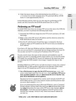
In Figure 2.7 a simple service evolution path is depicted starting from simple packet
switched services like MMS and going towards more demanding services like video
telephony. Video telephony has even tighter requirements on the delays than one-way
video streaming and a one-way end-to-end delay of less than 400 ms is needed for the
connection, while less than 150 ms is preferable [10].
2.3.2 Push-to-Talk over Cellular (PoC)
Push-to-talk over cellular (PoC) service is instant in the sense that the voice connection is
established by simply pushing a single button and the receiving user hears the speech
without even having to answer the call. While ordinary voice is bi-directional, the PoC
service is a one directional service. The basic PoC application may hence be described as a
walkie-talkie application over the packet switched domain of the cellular network. In
CS voice call +
PS MMS still pictures and videos
CS voice call +
PS real time 1-way video sharing
No CS component
2-way PS video telephony
<1 minute MMS delivery
Background delay requirements
<5 second video delay
Streaming requirements
<400 ms e2e delay
Conversational requirements
Packet switched
delay requirements
Person-to-person video
service evolution
Figure 2.7. Evolution of person-to-person video service
UMTS Services and Applications 19
addition to the basic voice communication functionality, the PoC application provides the
end user with complementary features like, for example:
Ad hoc and predefined communication groups;
Access control so that a user may define who is allowed to make calls to him/her;
‘Do-not-disturb’ in case immediate reception of audio is not desirable.
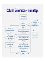
With ordinar y voice calls a bi-directional communication channel is reserved between
the end users throughout the duration of the call. In PoC, the channel is only set up to
transfer a short speech burst from one to possibly multiple users. Once this speech burst has
been transferred, the packet switched communication channel can be released. This
difference is highlighted in Figure 2.8.
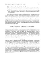
The speech packets are in the PoC solution carried from the sending mobile station to
the server by the OPRS/UMTS network. The server then forwards the packets to the
receiving mobile stations. In the case of a one-to-many connection, the server multiplies
the packets to all the receiving mobile stations. This is illustrated in Figure 2.9. The PoC
service is independent of the underlying radio access network. However, as we will see later
in this section as well as in Chapter 10, the characteristics of the PoC service also set tight
requirements on the underlying radio access network.
Telephone communication
One hour session Three minute airtime One hour session One hour airtime
Push-to-Talk
Figure 2.8. Push-to-talk versus ordinary telephone communication
Figure 2.9. Push to talk solution architecture
20 WCDMA for UMTS
In order for the PoC service to be well perceived by the end users it must meet multiple
requirements. Some examples of end user requirements are:
Simple user interface, for example, a dedicated push-to-talk button;
High voice quality and enough sound pressure in the speaker to work also in noisy
environments;
Low delay from pressing the push-to-talk button until it is possible to start talking, called
‘start-to-talk time’;
Low delay for the voice packets to receive the peer end, called voice through delay.
The end user is expected to be satisfied with the interactivity of the PoC service if the
start-to-talk delay is around or below two seconds, while the speech round trip time should
be kept lower than 1.5 seconds. The voice quality is usually evaluated by the mean opinion
score (MOS) and is naturally dependent on both the mobile station and the network
characteristics. A radio network that hosts PoC connections must, for example, be able to:
Provide always on packet data connections;
Reserve and release radio access resources fast in order to keep start-to-talk and speech
round trip times low;
Deliver a constant bit rate with low packet jitter during the duration of one speech burst.
Chapter 10 includes an investigation of the PoC service performance in a WCDMA
network.
2.3.3 Voice over IP (VoIP)
The driver for Voice-over-IP, VoIP, in fixed networks has been access to low cost long
distance and international voice calls. The driver for VoIP in cellular networks is rather to
enable rich calls. A rich call can be defined as a real time communication session between
two or more persons which consists of one or more media types. VoIP connection can be
complemented with 2-way vide o, streaming video, images, content sharing, gaming etc., see
Figure 2.10. VoIP and rich calls can be carried over WCDMA as the end-to-end network
Figure 2.10. VoIP as a building block for rich calls
UMTS Services and Applications 21
delay is low enough to meet the conversational service requirements. The QoS differentia-
tion and IP header compression are important to make an efficient VoIP service in WCDMA.
2.3.4 Multiplayer Games
We first group the existing multiplayer games into key categories based on their end user
requirements. Three reasonable categories are, according to the study in [11, 12], real time
action games, real time strategy games and turn based strategy games, see Figure 2.11. The
different categories are characterised by the properties and requirements given in Table 2.1.
Note that these requirements have been derived from studies using a fixed network
connection and not a cellular network connection. Although cellular networks behave
somewhat differently than fixed networks, and although mobile station displays are much
smaller than computer displays, the results give indications for what the maximum delay
may be in order to generate a nice gaming experience for the end user.
It can be noted that for experienced players it is an advantage to have significantly lower
end-to-end network delays than what is given by the requirement in Table 2.1; end-to-end
network delays down to as low as 70 to 80 ms are needed to satisfy the most demanding
Figure 2.11. Multiplayer game classification
Table 2.1. Multiplayer game delay and bit rate requirements [11, 12]
Gaming category End user delay requirements for average player
Real time action games End to end network delays < 300 ms
Real time strategy games End to end network delays < 900 ms
Turn based strategy games End to end network delays < 40 s
22 WCDMA for UMTS
users. The end-to-end networ k delay is particularly noticea ble for the users if some users
have low delays, like 70 ms, while others have higher delays, like 200 ms. Bearing in mind
that today’s WCDMA networks provide round trip times of 150–200 ms it is possible to
provide real time strategy and turn based strategy games, and even real time action games
over WCDMA.
The real time action games are constantly transmitting and receiving packets with typical
bit rates of 10–20 kbps. Such bit rates can be easily delivered over cellular networks.
However, these packets must be delivered with a very low delay which sets high require-
ments for the network performance. For real time strategy and tur n based strategy games
both the requirements on the bit rate and the end-to-end network delays are looser and there
is more freedom on how to map these services to radio channels. This mapping is discussed
in detail in Chapter 10.
2.4 Content-to-person Services
2.4.1 Browsing
During the early launch and development of WAP for mobile browsing, there were huge
expectations that browsing via the mobile station would take off rapidly. Because of several
reasons the take off did not happen as fast as expected. However, with better mobile station
displays – resolution and colour – and with higher bit rates and increased content, the
browsing experience on mobile station devices is increasing rapidly and service usage is
going up. There have been several releases of the WAP protocol stack, of which the most
important releases are WAP1.1 and WAP2.0; see further Figure 2.12. The WAP version
denoted WAP1.1 was approved in June 1999 and the first products based on this version
were launched later in the same year. The WAP2.0 version was released in July 2001 by the
WAP forum, which is currently part of the Open Mobile Alliance (OMA). The most
important difference between WAP1.1 and WAP2.0 is that WAP2.0 is based on the standard
Internet transport protocols (TCP/IP, HTTP/XHTML), while the WAP1.1 release utilises
WAP1.1 specific transport protocols. From an end user point of view, the TCP/IP protocols
provide faster download of large content size.
The focus in WAP1.1 development was to make browsing perform well in systems with
large packet round trip times and with limited bit rates. That is, WAP1.1 enables the
WAP 1.1 WAP 2.0
WML WML + XHTML
UDP TCP
IP IP
Figure 2.12. Evolution of the WAP protocol stacks
UMTS Services and Applications 23
transmitter to send the packets almost at once, witho ut waiting for connection establishment
between the communication peers. This makes WAP1.1 fast for small packets over
unreliable links. The weakness is that the link will usually not be fully utilised if the file
to transfer is large. The decreased link utilisation lowers the end user bit rate for large files if
the air interface bit rate is high.
WAP2.0 introduces standard Internet protocols to the WAP protocol stacks. Because the
TCP/IP protocols have well developed link and congestion management algorithms, this
makes WAP2.0 more efficient when transferring large files over radio links with high bit
rates. To make TCP even more efficient for mobile systems, a particular flavour called
wireless TCP (wTCP) has been defined. The wTCP protocol is based on standard TCP
features, but in wTCP the support of certain features is mandatory and recommendations for
parameter values have been aligned to cope with the higher packet round trip time in
wireless networks. The higher link utilisation with TCP/IP for large files is illustrated in
Figure 2.13 assuming WCDMA 128 kbps connection. The difference between WAP1.1 and
WAP2.0 download times is quite small for small page sizes because of the low round trip
time in WCDMA. A low round trip time helps standard Internet protocols perform
satisfactorily over WCDMA without special optimisation.
From a user perspective it is crucial that browsing is easily accessible and fast. Rough
performance requirements for browsing are that the first page download time is lower than
10 s and for the second page download, lower than 4 to 7 s is preferred [10]. However, bear
in mind that end user service requirements are different from market to market and also in
different market segments within the same market. Another user requirement is that it should
be possible to use browsing smoothly when travelling by car, train or bus. This requires
efficient handling of cell reselections in order to prevent connection breaks. Because
WCDMA utilises handover for packet switched data, there are no breaks at cell reselection.
From a network perspective the first page download is different from the secon d page
download. The reason is that the first page download time may include GPRS attach,
security procedures, PDP context activation and radio bearer set-up times depending on how
the network and the mobile station have been configured. For the second and consecutive
pages the download time will be lower because the initial set-up messages have already been
sent. The second page download time is mainly limited by the basic packet round trip time,
0
2
4
6
8
10
12
10 Kbytes 20 Kbytes 100 Kbytes
Page size
Seconds
WAP1.1
WAP2.0
Figure 2.13. Page download time with WAP1.1 and WAP2.0
24 WCDMA for UMTS
the radio channel bit rate, TCP/IP efficiency, HTTP versions and possibly also the radio
bearer set-up time depending on the idle period from the last page download.
2.4.2 Audio and Video Streaming
Multimedia streaming is a technique for transferring data such that it can be processed as a
steady and continuous stream. Streaming technologies are becoming increasingly important
with the growth of the Internet because most users do not have fast enough access to
download large multimedia files quickly. Mobile station memory may also limit the size of
the downloads. With streaming, the client browser or plug-in can start displaying the data
before the entire file has been transmitted.
For streaming to work, the client side receiving the data must be able to collect the data
and send it as a steady stream to the application that is processing the data and converting it
to sound or pictures. Streaming applications are very asymmetric and therefore typically
withstand more delay than more symmetric conversational services. This also means that
they tolerate more jitter in transmission. Jitter can be easily smoothed out by buffering.
Internet video products and the accompanying media industry as a whole are clearly
divided into two different target areas: (1) Web broad cast and (2) video streaming on-
demand. Web broadcast providers usually target very large audiences that connect to a
highly performance-optimised media server (or choose from a multitude of servers) via
the actual Internet. The on-demand services are more often used by big corporations that
wish to store video clips or lectures to a server connected to a higher bandwidth local
intranet – these on-demand lectures are seldom used simultaneously by more than hundreds
of people.
Both application types use basically similar core video compression technology, but the
coding bandwidths, level of tuning within networ k protocol use, and robustness of server
technology needed for broadcast servers differ from the technology used in on-demand,
smaller-scale systems. This has led to a situation where the few major companies developing
and marketing video streaming products have specialised their end user products to meet the
needs of these two target groups. Basically, they have optimised their core products
differently: those directed to the ‘28.8 kbps market’ for bandwidth variation-sensitive
streaming over the Internet and those for the 100–7300 kbps intranet market.
At the receiver the streaming data or video clip is played by a suitabl e independent media
player application or a browser plug-in. Plug-ins can be downloaded from the Web, usually
free of charge, or may be readily bundled to a browser. This depends largely on the browser
and its version in use – new browsers tend to have integrated plug-ins for the most popular
streaming video players.
In conclusion, a client player implementation in a mobile system seems to lead to an
application-level module that could handle video streams independently (with independent
connection and playback activation) or in parallel with the browser application when the
service is activated from the browser. The module would interface directly to the socket
interface of applied packet network protocol layers, here most likely UDP/IP or TCP/IP.
Example terminals supporting streaming services are shown in Figure 2.14.
2.4.3 Content Download
Content download examples are shown in Figure 2.15: application downloads, ringing tone
downloads, video clips and MP3 music. The content size can vary largely from a few kB
UMTS Services and Applications 25
ringing tones to several MB music files. The download times should preferably be low,
which puts high requirements on the radio bit rate, especially for the large downloads with
several 100 kB.
2.4.4 Multimedia Broadcast Multicast Service, MBMS
A new service introduced in 3GPP Release 6 specifications is Multimedia Broadcast
Multicast Service (MBMS). There are two high level modes of operation in MBMS, as
given in [13]
1. Broadcast mode, which allows sending audio and video. The already existing Cell
Broadcast Service (CBS) is intended for messaging only. The broadcast mode is expected
to be a service without charging and there are no specific activation requirements for this
mode.
2. Multicast mode allows sending multimedia data for the end users that are part of a
multicast subscription group. End users need to monitor service announcements regard-
ing service availability, and then they can join the currently active service. From the
network point of view, the same content can be provided in a point-to-point fashion if
there are not enough users to justify the high power transmission. A typical example in
Figure 2.14. Example streaming terminals
Figure 2.15. Example content download
26 WCDMA for UMTS
3GPP has been the sport results service where, for example, ice hockey results would be
available as well as video clips of the key events in different games of the day. Charging
is expected to be applied for the multicast mode.
From the radio point of view, MBMS is considered an application independent way to
deliver the MBMS User Services, which are intended to deliver to multiple users
simultaneously. The MBMS User Services can be classified into three groups as follows
[14]:
1. Streaming services, where a basic example is audio and video stream;
2. File download services;
3. Carousel service, which can be considered as a combination of streaming and file
download. In this kind of service, an end user may have an application which is provided
data repetitively and updat es are then broadcast when there are changes in the content.
For MBMS User Services, an operator controls the distribution of the data. Unlike CBS,
the end user needs first to join the service and only users that have joined the service can see
the content. The charging can then be based on the subscription or based on the keys which
enable an end user to access the data. The MBMS content can be created by the operator
itself or by a third party and, as such, all the details of what an MBMS service should look
like will not be specified by 3GPP, but left for operators and service providers. One possible
MBMS high level architecture is shown in Figure 2.16, where the IP multicast network refers
here to any server providing MBMS content over the Internet.
The example data rates in [14] range from the 10 kbps text-based information to the
384 kbps video distribution on MBMS. The codecs are expected to be the current ones –
such as AMR for voice – to ensure a large interoperability base for different terminals for the
services being provided. The MBMS causes changes mostly to Layer 2/3 protocols as
described in Chapter 7 in more detail.
Figure 2.16. Example MBMS high level architecture
UMTS Services and Applications 27
2.5 Business Connectivity
Business connectivity considers access to corporate intranet or to Internet services using
laptops. We consider shortly two aspects of business connectivity: end-to-end security and
the effect of radio latency to the application performance. End-to-end security can be
obtained using Virtual Private Networks, VPN, for the encryption of the data. One option is
to have a VPN client located on the laptop and the VPN gateway in the corporate premises.
Such an approach is often used by large corporates that are able to obtain and maintain
required equipment for the remote access service. Another approach uses a VPN connection
between the mobile operator core site and the company intranet. The mobile network uses
standard UMTS security procedures. In this case the company only needs to subscribe to the
operator’s VPN service and obtain a VPN gateway. These two approaches are illustrated in
Figure 2.17.
The business connectivity applications can be, for example, web browsing, email access
or file download. The application performance should preferably be similar to the
performance of DSL or WLAN. The application performance depends on the available bit
rate but also on the network latency. The network latency is here measured as the round trip
time. The round trip time is the delay of a small IP packet to travel from the mobile to a
server and back. The effect of the latency is illustrated using file download over Transmis-
sion Control Protocol, TCP, in Figure 2.18. The download process includes TCP connection
establishment and file download, including TCP slow start. The end user experienced bit rate
is defined here as the download file size divided by the total time. The delay components are
illustrated in Figure 2.19.
The user experienced bit rates with round trip times between 0 and 600 ms are shown in
Figure 2.20. This figure assumes that a dedicated channel with 384 kbps already exists and
no channel allocation is required. The curves show that a low round trip time is beneficial,
especially for small file sizes, due to TCP slow start. WCDMA round trip time is analysed in
detail in Chapter 10 and it is typically 150–200 ms. Figure 2.21 shows the download time
with different round trip times. The download time of a less than 100 kB file is below 3 s as
Figure 2.17. Virtual private network architectures
28 WCDMA for UMTS
UE Server
SEQ
SEQ, ACK
ACK
FTP get
File download with slow start
TCP connection
establishment
FTP download
including slow start
Start file download
Complete file received
RNC
User experienced bit rate = File size / total download time
Figure 2.18. Example signalling flow in file download using TCP
384 kbps
TCP slow
start
Download at max
throughout
TCP
connection
establishment
Figure 2.19. Example file download using TCP
0
50
100
150
200
250
300
350
400
10 100 1000
File size [kB]
Bit rate [kbps]
0 ms
50 ms
100 ms
150 ms
200 ms
300 ms
600 ms
End user performance
improves with lower round
trip time
Figure 2.20. Effect of round trip time to the user experienced bit rate with Layer 1 bit rate of 384 kbps
UMTS Services and Applications 29
long as the round trip time is below 300 ms. Low round trip time will be more relevant if we
need to download several small files using separate TCP sessions.
The application performance is also affected by the application protocol, e.g. HTTP 1.1 vs
HTTP 1.0 in web browsing. A web page typically consists of several objects: text and a
number of pictures. In the case of HTTP 1.0 each object is downloaded in a separate TCP
session, while for HTTP 1.1 all objects from the same server can be downloaded in one TCP
connection. The difference is depicted in Figure 2.22. It is beneficial to use HTTP 1.1 to
minimise the effect of TCP slow start on the application performance.
2.6 IP Multimedia Sub-system, IMS
IP Multimedia Sub-system, IMS, allows operators to provide their subscribers with multi-
media services that are built on Internet applications and protocol s [15]. IMS enables IP
connectivity between users using the same control and charging mechanisms. The basic
session initiation capabilities provided by SIP protocol are utilised to establish peer-to-peer
sessions. The IMS concept is shown in Figure 2.23.
0
2
4
6
8
10
12
14
16
10 100 1000
File size [kB]
Download time [s]
600 ms
300 ms
200 ms
100 ms
0 ms
Download time is <3 s for
100 kB file as long as round
trip time <300 ms
Figure 2.21. Effect of round trip time on the download times with Layer 1 bit rate of 384 kbps
HTTP 1.0
HTTP 1.1
TCP Session #1
SLOW
-
START
Object #1
TCP Session #2
SLOW
-
START
Object #2
TCP Session #3
SLOW
-
START
Object #3
TCP Session #1
SLOW
-
START
Object #1
Object #2 Object #3
Figure 2.22. HTTP 1.1 uses one TCP connection for multiple objects
30 WCDMA for UMTS
IMS provides the means for networ k operators to maintain their role in the value chain by
providing new multimedia services and predictable end user performance. The same
platform can be used in both real time serv ices, like VoIP, and non-real time services, like
content sharing. The IMS network elements are introduced in Chapter 5.
2.7 Quality of Service Differentiation
Chapter 10 covers end-to-end application performance assuming that the system load is
reasonably low. When the system load gets higher, it becomes important to prioritise the
different services according to their requirements. This prioritisation is called QoS
differentiation. 3GPP QoS architecture is designed to provide this differentiation [16].
The terminology is shown in Figure 2.24.
The most relevant parameters of the four UMTS QoS classes are summarised in Table 2.2.
The main distinguishing factor between the four traffic classes is how delay-sensitive the traffic
Figure 2.23. Basic principles of the IP Multimedia Sub-system
Figure 2.24. Definition of quality of service differentiation
UMTS Services and Applications 31
is: the conversational class is meant for very delay-sensitive traffic, while the background
class is the most delay-insensitive. There are, further, three different priority categories,
called allocation/retention priority categories, within each QoS class. Interactive has also
three traffic handling priorities. Conversational and streaming class parameters also include
the guaranteed bit rate and the transfer delay parameters. The guaranteed bit rate defines the
minimum bearer bit rate that UTRAN must provide and it can be used in admission control
and in resource allocations. The transfer delay defines the required 95th percentile of the
delay. It can be used to define the RLC operation mode (acknowledged, non-acknowledged
mode) and the number of retransmissions.
The conversational class is characterised by low end-to-end delay and symmetric or nearly
symmetric traffic between uplink and downlink in person-to-person communications. The
maximum end-to-end delay is given by the human perception of video and audio conversa-
tion: subjective evaluations have shown that the end-to-end delay has to be less than 400 ms.
The streaming class requires bandwidth to be maintained like conversational class but
streaming class tolerates some delay variations that are hidden by dejitter buffer in the
receiver. The interactive class is characterised by the request response pattern of the end user.
At the message destination there is an entity expecting the message (response) within a
certain time. The background class assumes that the destination is not expecting the data
within a certain time.
UMTS QoS classes are not mandatory for the introduction of any low delay service. It is
possible to support streaming video or conversational Voice over IP from an end-to-end
performance point of view by using just background QoS class. QoS differentiation becomes
useful for the network efficiency during high load when there are services with different
delay requirements. If the radio networ k has knowledge about the delay requirements of the
different services, it will be able to prioritise the services accordingly and improve the
efficiency of the network utilisation. The qualitative gain of the QoS differentiation is
illustrated in Figure 2.25. Considerable efficiency gains can be obtained in Step 2 just by
introducing a few prioritisation classes within interactive or background class by using
allocation and retention parameters, ARP. The pure prioritisation in packet scheduling is
not alone enough to provide full QoS differentiation gains. Users within the same QoS and
ARP class will share the available capacity. If the number of users is simply too high, they
will all suffer from bad quality. In that case it would be better to block a few users to
guarantee the quality of the existing connections, like streaming videos. That is provided in
Step 3 in Figure 2.25 with guaranteed bit rate streaming. The radio network can estimate the
available radio capacity and block an incoming user if there is no room to provide the
required bandwidth witho ut sacrificing the quality of the existing connections. Finally Step 4
allows further differentiation between guaranteed bit rate services with different delay
Table 2.2. UMTS QoS classes and their main parameters
Conversational Streaming Interactive Background
class class class class
Transfer delay 80 ms – 250 ms – — —
Guaranteed bit rate (kbps) Up to 2 Mbps Up to 2 Mbps — —
Traffic handling priority — — 1,2,3 —
Allocation/retention priority 1,2,3 1,2,3 1,2,3 1,2,3
32 WCDMA for UMTS
requirements. If the delay requirements are known, the WCDMA RAN can allocate suitable
radio parameters – like retransmission parameters – for the new bearer.
An example QoS differentiation scheme is shown in Figure 2.26 with ten different QoS
categories: six guaranteed bit rate categories and four non-real time categories. It is assumed
in this case that traffic handling priority is equal to allocation and retention priority, and there
is no prioritisation within the background class.
The next three figures illustrate Steps 1, 2 and 4. Figure 2.27 shows an example where all
the services have the sam e QoS parameters and the same treatment. In this case, all services
share the network resources equally: they get the same bit rate and experience the same
delay. The network dimensioning must be done so that this bit rate or delay fulfils the most
stringent requirements of the services provided in the network. The background type of
service, like sending of MMS, will get the same quality, which is unnecessarily good and
Network resource utilisation
(Spectrum, hardware, Iub,
RNC, core)
Step 1
No QoS
Step 2
QoS priorities
Step 3
Streaming QoS
Step 4
Conversational
QoS
Prioritise most
delay critical
services
Block users to
guarantee quality
if load high
Low delay (no
retransmission)
Exact gain depends on the service
requirements and on the network
parameters and algorithms
Figure 2.25. Qualitative gain illustration for QoS differentiation
Conversational ARP=1
Conversational ARP=2
Conversational ARP=3
Streaming ARP=1
ARP=2
ARP=3
Streaming
Streaming
ARP=THP=1Interactive
ARP=THP=2Interactive
ARP=THP=3Interactive
ARP=3Background
Guaranteed bit rate
Low delay guaranteed bit rate
Prioritisation
1
10
2
…
Figure 2.26. Example ten categories by taking a subset of UMTS QoS classes
UMTS Services and Applications 33
wastes network resources. Figure 2.28 shows the case where there are three different pipes
with QoS prioritisation in packet scheduling. This approach already provides QoS differ-
entiation and makes the network dimensioning requirements less stringent. Figure 2.29 adds
two further pipes with guaranteed bit rates.
The layered architecture of a UMTS bearer service is depicted in Figure 2.30; each bearer
service on a specific layer offers its individual services using those provided by the layers
below. The QoS parameters are given by the core network to the radio network in radio
access bearer set-up.
Figure 2.31 illustrates the mechanisms to define the QoS parameters in radio access bearer
set-up.
1. The UE can request QoS parameters. In particular, if the application requires guaranteed
bit rate stream ing or conversational class, it has to be requested by UE, otherwise, it
cannot be given by the networ k.
2. The access point node, APN, in GGSN can give QoS parameters according to operator
settings. Some services may be accessed via certain APNs. That allows the operator to
control the QoS parameters for different services and makes it also possible to prioritise
operator hosted services compared to accessing other services.
3. The home location register, HLR, may contain subscriber specific limitations for the QoS
parameters.
4. The WCDMA radio network must be able to provide the QoS differentiation in packet
handling.
Figure 2.27. No QoS differentiation – all services use the same QoS parameters
34 WCDMA for UMTS
Figure 2.28. QoS prioritisation used with three classes
Figure 2.29. QoS differentiation with two guaranteed bit rate classes and three classes for non-real
time prioritisation
UMTS Services and Applications 35
TE UTRANMT TECN
Gateway
CN Iu
EDGE
NODE
End-to-End Service
TE/MT Local
Bearer Service
UMTS Bearer Service
External Bearer
Service
Radio Access Bearer Service
CN Bearer
Service
Iu Bearer
Service
Backbone
Network Service
Radio Bearer
Service
UTRA
FDD/TDD
Service
Physical Bearer
Service
UMTS
Figure 2.30. Architecture of a UMTS bearer service
Figure 2.31. The role of UE, GGSN and HLR in defining QoS class
36 WCDMA for UMTS
2.8 Capacity and Cost of Service Delivery
This section considers the maximum capacity of the radio network in delivering new services
and estimates the cost of the service delivery from the UMTS network equipment point of
view.
2.8.1 Capacity per Subscriber
The maximum capacity per subscriber for data and for voice traffic is presented below. The
data traffic is presented as the maximum amount of downloaded megabytes (MB) of data per
average subscriber per month. The voice traffic is presented as the maximum mobile-to-
mobile voice minutes per average subscriber per month. The following assumptions are used
in the calculations:
WCDMA carrier capacity is 800 kbps/cell or 80 voice channels/cell, see Chapter 12 for
more details;
High-Speed Downlink Packet Access, HSDPA carrier capacity is 2000 kbps/cell, see
Chapter 11 for more details;
Cell capacity utilisation is 80 % during busy hours;
Busy hour carries 20 % of daily traffic.
There are 1000 subscribers per site;
There are three sectors per site;
The percentage of the traffic carried by the busy hour represents how equally the traffic is
distributed during the day. That number is affected by the pricing schemes. Attractive
evening or weekend pricing schemes can make the traffic distribution more equal (busy hour
carries less than 20 % of the traffic) and more traffic can be carried by the same network.
The assumption of 1000 subscribers is a typical average figure for large network operators.
More subscribers per site can be found in dense areas. The capacity per subscriber per day
can be calculated as follows with a 10 MHz WCDMA 2þ2þ2 site configuration:
0:8 Mbps=cell
8 bits=byte
Á 6 cells Á 3600 s=hour
80 %
20 %
1
1000 subs
Á 30 days=month
¼ 260 MB=sub=month ð2:1Þ
The maximum data capacity with WCDMA 10 MHz spectru m allocation is 260 MB/sub/
month and with HSDPA 650 MB/sub/month. The voice capacity is up to 1725 minutes/sub/
month. The data capac ities are shown in Figure 2.32 and voice capacities in Figure 2.33.
Since data and voice share the same spectrum, the final capacity depends on the traffic share
between data and voice traffic. With a 50/50 split, the capacity could be 325 MB þ 862 voice
minutes per month. These capacity numbers indicate that there is a lot of traffic growth
potential with WCDMA on top of today’s traffic numbers. Global average voice traffic is
currently 150–200 minutes per month.
UMTS Services and Applications 37
Most UMTS operators also have GSM900/1800 spectrum that can provide additional
capacity for voice and data services. Also, new spectrum for third generation systems will be
available at around 2.6 GHz. Chapter 1 gives an overview of the spectrum.
2.8.2 Cost of Capacity Delivery
This section presents cost estimates of delivering megabytes of data or voice minutes over
the WCDMA mobile network. The target is to present the calculation methods and to show
approximate cost levels. The cost numbers include the depreciation of the radio and the core
network capital expenditures (capex) without any implementation costs. The following
components are included: base stations, radio transmission, RNC, core network and
operations solutions. The price of all this equipment is calculated per transceiver unit
(TRX). The assumed per TRX prices are between 15 and 40 ks. The pricing depends on a
number of factors and, therefore, a large scale is used. A capex depreciation period of six
years is assumed. The mobile network delivery cost per downloaded MB in s can be
calculated as follows:
Price per TRX½s
0:8 Mbps
8 bits=byte
Á
3600 s=hour Á 80 %
2 %
Á 365 days=year Á 6 years
ð2:2Þ
0
100
200
300
400
500
600
700
WCDMA
1+1+1
WCDMA
2+2+2
HSDPA
1+1+1
HSDPA
2+2+2
MB/sub/month
Figure 2.32. Data capacity MB/subscriber/month
0
200
400
600
800
1000
1200
1400
1600
1800
2000
WCDMA 1+1+1 WCDMA 2+2+2
Voice minutes/sub/month
Figure 2.33. Voice capacity minutes/subscriber/month
38 WCDMA for UMTS
The delivery cost for data is shown in Figure 2.34 and for voice in Figure 2.35. The results
show that it is possible to push the data delivery capex down to approximately 0.01 s/MB,
that means 1 eurocent/MB, and a voice minute below 0.2 eurocent/minute.
The high busy hour utilisation of 80 % can be used for the case when additional capacity is
built. If we calculate the delivery cost over the whole network, the busy hour utilisation will
be lower on average because parts of the sites are built to provide coverage and they do not
collect high traffic volumes.
The mobile network capex depreciation represents only part of the operator costs. Other
costs include, for example, leased line transmission costs, interconnection fees, customer
acquisition, advertising and customer care. Therefore, the sales prices cannot be as low as
the presented produc tion cost figures which only include capex depreciation. The capacity
and the cost calculations above still demonstrate that WCDMA is able to deliver high
amounts of traffic with reas onable cost, which are key requirements for enabl ing new
services.
Delivery cost of downloaded MB
0.000
0.002
0.004
0.006
0.008
0.010
0.012
0.014
14 16 18 20 22 24 26 28 30 32 34 36 38 40
Price per TRX [k
[EURO
Figure 2.34. Delivery cost of downloaded data MB
Delivery cost of mobile-to-mobile voice minute
0.0000
0.0002
0.0004
0.0006
0.0008
0.0010
0.0012
0.0014
0.0016
0.0018
0.0020
14 16 18 20 22 24 26 28 30 32 34 36 38 40
Price per TRX [k
[EURO
Figure 2.35. Delivery cost of mobile-to-mobile voice minute
UMTS Services and Applications 39
2.9 Service Capabilities with Different Terminal Classes
WCDMA does not use the same principle as GSM with terminal class mark. WCDMA
terminals shall tell the network, upon connection set-up, a larger set of parameters indicating
the radio access capabilities of the particular terminal. These capabilities determine, for
example, the maximum user data rate supported in a particular radio configuration, given
independently for the uplink and downlink directions. To provide guidance on which
capabilities should be applied together, reference terminal radio access capability combina-
tions have been specified in 3GPP standardisation, see [17]. The following reference
combinations have been defined for 3GPP Release ’99:
32 kbps class. This is intended to provide a basic speech service, including AMR speech
as well as some limited data rate capabilities up to 32 kbps.
64 kbps class. This is intended to provide a speech and data service, with simulta neous
data and AMR speech capability.
144 kbps class. This class has the air interface capability to provide, for example, video
telephony or various other data services.
384 kbps class is being further enhanced from 144 kbps and has, for example, multicode
capability, which points toward support of advanced packet data methods provided in
WCDMA.
768 kbps class has been defined as an intermediate step between 384 kbps and 2 Mbps
class.
2 Mbps class. This is the state-of-th e-art class and has been defined for the d ownlink
direction only.
These classes are defined so that a higher class has all the capabilities covered by a lower
class. It should be noted that terminals may deviate from these classes when giving their
parameters to the network, thus 2 Mbps is possible for the uplink also, though not covered by
any of the classes directly.
3GPP specifications include performance requirements for the bit rates up to 384 kbps, for
more details see Section 12.5. Therefore, it is expected that terminals up to 384 kbps will be
available in the initial deployment phase.
High-Speed Downlink Packet Access, HSDPA, further enhances the WCDMA bit rate
capabilities. HSDPA terminal capabilities are defined in 3GPP Release 5 and extend beyond
10 Mbps. HSDPA is covered in detail in Chapter 11.
2.10 Location Services in WCDMA
2.10.1 Location Services
Location-based services and applications are expected to become one of the new dimensions
in UMTS. A location-based service is provided either by a teleoperator or by a third party
service provider that utilises available information on the terminal location. The service is
either push (e.g. automatic distribution of local information) or pull type (e.g. localisation of
emergency calls). Other possible location-based services are discount calls in a certain area,
40 WCDMA for UMTS
broadcasting of a service over a limited number of sites (broadcasting video on demand), and
retrieval and display of location-based information, such as the location of the nearest gas
stations, hotels, restaurants, and so on. Figure 2.36 shows an example. Depending on the
service, the data may be retrieved interactively or as background. For instance, before
travelling to an unknown city abroad one may request night-time download of certain points
of interest from the city. The downloaded information typically contains a map and other
data to be displayed on top of the map. By clicking the icon on the map, one gets information
from the point. Information to be downloaded background or interactively can be limited by
certain criteria and personal interest.
The location information can be input by the user or detected by the network or mobile
station. The network architecture of the location services is discussed in Chapter 5. Release
’99 of UMTS specifies the following positioning methods:
the cell coverage based positioning method;
Observed Time Difference Of Arrival – Idle Period DownLink (OTDOA-IPDL);
network-assisted GPS methods.
These methods are complementary rather than competing, and are suited for different
purposes. These approaches are introduced in the following sections.
2.10.2 Cell Coverage Based Location Calculation
The cell coverage based location method is a network based approach, i.e., it does not
require any new functionalities in the mobile. The radio network has the location informa-
tion with a cell level accuracy when the mobile has been allocated a dedicated channel or
when the mobile is in cell_FACH or cell_PCH states. These states are introduced in Chapter
7. If the mobile is in idle state, its location with cell accuracy can be obtained by forcing the
mobile to cell_FACH state with a location update as illustrated in Figure 2.37.
Figure 2.36. 3G concept phone showing location-based service
UMTS Services and Applications 41
The accuracy of the cell coverage based method depends heavily on the cell size. The
typical cell ranges in the urban area are below 1 km and in the dense urban area a few
hundred meters providing fairly accurate location information.
The accuracy of the cell coverage based approach can be improved by using the round trip
time measurement that can be obtained from the base station. That information is available
in cell_DCH state and it gives the distance between the base and the mobile station.
2.10.3 Observed Time Difference Of Arrival, OTDOA
The OTDOA method is based on the mobile measurements of the relative arrival times of the
pilot signals from different base stations. At lea st three base stations must be received by the
mobile for the location calculation, as shown in Figure 2.38. A measurement from two base
stations defines a hyperbola. With two measurement pairs, i.e. with three base stations, the
location can be calculated.
In order to facilitate the OTDOA location measurements and to avoid near–far problems,
the WCDMA standard includes idle periods in downlink, IPDL. During those idle periods
the mobile is able to receive the pilot signal of the neighbour cells even if the best pilot
signal on the same frequency is very strong. A typical frequency of the idle periods is 1 slot
every 100 ms, i.e. 0.7 % of the time . The IPDL–OTDOA measurements are shown in
Figure 2.39.
The network needs to know the relative transmission times of the pilot signals from
different base stations to calculate the mobile location. That relative timing information can
be obtained by:
1. OTDOA measurements by the location measurement unit at the base station. The base
station measures the relative timing of the adjacent cells. The measurement is similar to
the OTDOA measur ements by the mobile.
2. The GPS receiver at the base station.
Figure 2.37. Location calculation with cell coverage combined with round trip time
42 WCDMA for UMTS
The accuracy of the OTDOA measurements can be in the order of up to tens of meters in
very good conditions when several base stations in line-of-sight can be received by the
mobile. In practice, such ideal measurement conditions are not typically available in cellular
networks. The accuracy depends on the following factors:
1. The number of base stations that the mobile can receive. A minimum of three is required.
If more base stations can be received, the accuracy is improved.
2. The relative locations of the base stations. If the base stations are located in different
directions from the mobile, the accuracy is improved.
3. The line-of-s ight. If there is a line-of-sight between the mobile and the base station, the
accuracy is improved.
The requirement of receiving at least three base stations is challenging in the cellular
networks. The target of the network planning is to create clear dominance areas of the cells
Figure 2.38. Location calculation with three base stations
Figure 2.39. IPDL (Idle Period Downlink) – OTDOA (Observed Time Difference of Arrival)
UMTS Services and Applications 43