Wcdma for umts radio access for third genergation mobile communacations phần 3 doc
Bạn đang xem bản rút gọn của tài liệu. Xem và tải ngay bản đầy đủ của tài liệu tại đây (730.65 KB, 48 trang )
The cdma2000 multicarrier option is covered in more detail in Chapter 14, as standardised
by 3GPP2.
4.5.4 TR46.1
The WIMS W-CDMA was not based on work derived from an existing second generation
technology but was a new third generation technology proposal with no direct link to any
second generation standardisation. It was based on the constant processing gain principle
with a high number of multicodes in use, thus showing some fundamental differences, but
also a level of commonality, with WCDMA technology in other forums.
4.5.5 WP-CDMA
WP-CDMA (Wideband Packet CDMA) resulted from the convergence between W-CDMA
N/A of T1P1 and WIMS W-CDMA of TR46.1 in the US. The main features of the WIMS
W-CDMA proposal were merged with the principles of W-CDMA N/A. The merged
proposal was submitted to the ITU-R IMT-2000 process towards the end of 1998, and to
the 3GPP process at the beginning of 1999. Its most characteristic feature, compared with
the other WCDMA-based proposals, was a common packet mode channel operation for the
uplink direction, but there were also a few smaller differences.
4.6 Creation of 3GPP
As similar technologies were being standardised in several regions around the world, it
became evident that achieving identical specifications to ensure equipment compatibility
globally would be very difficult with work going on in parallel. Also, having to discuss
similar issues in several places was naturally a waste of resources for the participating
companies. Therefore, initiatives were made to create a single foru m for WCDMA
standardisation for a common WCDMA specification.
The standardisation organisations involved in the creation of the 3 rd Generation Partner-
ship Project (3GPP) [9] were ARIB (Japan), ETSI (Europe), TTA (Korea), TTC (Japan) and
T1P1 (USA). The partners agreed on joint efforts for the standardisation of UTRA, now
standing for Universal Terrestrial Radio Access, as distinct from UTRA (UMTS Terrestrial
Radio Access) from ETSI, also submitted to 3GPP. Companies such as manufacturers and
operators are members of 3GPP through the respective standardisation organisation to which
they belong, as illustrated in Figure 4.2.
Later during 1999, CWTS CWTS (the China Wireless Telecommunication Standard
Group) also joined 3GPP and contributed technology from TDSCDMA, a TDD-based
CDMA third generation technology already submitted to ITU-R earlier.
Figure 4.2. 3GPP organisational partners
Background and Standardisation of WCDMA 67
3GPP also includes market representation partners: GSM Association, UMTS Forum,
Global Mobile Suppliers Association, IPv6 Forum and Universal Wireless Communications
Consortium (UWCC).
The work was initiated formally at the end of 1998 and the detailed technical work was
started in early 1999, with the aim of having the first version of the common specification,
called Release ’99, ready by the end of 1999.
Within 3GPP, four different technical specification groups (TSGs) were set up as follows:
Radio Access Network TSG;
Core Network TSG;
Service and System Aspects TSG;
Terminals TSG.
Within these groups the one most relevant to the WCDMA technology is the Radio Access
Network TSG (RAN TSG), which has been divided into four different working groups as
illustrated in Figure 4.3.
The RAN TSG will produce Release ’99 of the UTRA air interface specification. The
work done within the 3GPP RAN TSG working groups has been the basis of the technical
description of the UTRA air interface covered in this book. Without such a global initiative,
this book would have been forced to focus on a single regional specification, though with
many similarities to those of other regions. Thus, the references throughout this book are to
the specification volumes from 3GPP.
During the first half of 1999 the inputs from the various participating organisations were
merged in a single standard, leaving the rest of the year to finalise the detailed parameters for
the first full release, Release ’99, of UTRA from 3GPP. The member organisations have
undertaken individually to produce standard publications based on the 3GPP specification.
Thus, for example, the Release ’99 UMTS specifications from ETSI are identical to the
Release ’99 specifications produced by 3GPP. The latest specifications can be obtained from
3GPP [9].
During 2000, further work on GSM evolution was moved from ETSI and other forums to
3GPP, including work on GPRS and EDGE. A new TSG, TSG GERAN was set up for this
purpose.
Figure 4.3. 3GPP RAN TSG working groups
68 WCDMA for UMTS
4.7 How does 3GPP Operate?
In 3GPP the work is organised around work items, which basically define the justification
and objective for a new feature. For a smaller topic there need be only a single work item
in one working group if the impacts are limited to that group, or at least are mainly for
the specifications under the responsibility of that group. For bigger items, such as HSDPA,
there were work tasks done for each of the four RAN working groups and these work tasks
were under a common work item, a building block, named HSDPA.
Of the currently on-going items, MBMS is a having a feature-level description, as that is
also covering other groups than TSG RAN, and, respectively, TSG RAN is having a work
item as a building block for the feature.
The work item sheets also usually contain the specifications to be impacted as well as the
expected schedule of the work the latter is usually rather optimistic though. A work item
needs to have four supporting companies but also it needs to have justification that can be
agreeable at the respective TSG RAN level. (Note that some variations in the way of working
exist between TSGs). For a larger topic, quite often a feasibility study (or study item in TSG
RAN) is needed before the decision of actually creating a work item. A feasibility study will
simply focus on the pain vs. gain ratio of the new feature, comparing the advantages and the
resulting impacts on the equipment and existing features (the latter is known as backwards
compatibility).
For each work item a raporteur is nominated, who has the responsibility of coordinating
the work and reporting the progress from WGs to TSG level. At TSG level, every meeting
(called a plenary) monitors progress every three months and makes any necessary
synchronisation between working groups and TSGs. Sometimes a work item is determined
not to have reached the expected target and it may be altered or removed from the work
program. Once the work item is completed in all working groups, Change Requests (CRs)
are brought to the plenary for approval. CRs contain the changes needed in each particular
specification and once the plenary level approval is obtained, the specification will be
updated to a new version with the changes resulting from the new feature. The simplified
illustration of the process from feasibility study to specification finalisation is shown in
Figure 4.4. The latest work item descriptions can be found from [9].
Figure 4.4. Example of 3GPP standardisation process
Background and Standardisation of WCDMA 69
Creation of the specification does not necessarily mean that everything is 100%
completed. Typically, some meeting rounds are then taken for potential corrections, which
usually emerge as implementations proceed and details are being verified in implementation
and testing. The CRs are used to introduce the corrections, they are agreed in working
groups and, once approved by the following TSG plenary meeting, the CRs are then include d
in the specification.
4.8 Creation of 3GPP2
Work done in TR45.5 and TTA was merged to form 3GPP2, focused on the development of
cdma2000 Direct-Sequence (DS) and Multicarrier (MC) mode for the cdma2000 third
generation component. This activity has been running in parallel with the 3GPP project, with
participation from ARIB, TTC and CWTS as member organisations. The focus shifted to
MC-mode after global harmonisation efforts, but later work started to focus more on the
narrowband IS-95 evolution, as reflected in the IS-2000 standards series.
4.9 Harmonisation Phase
During 1999, efforts were made to bring further harmonisation and convergence between the
CDMA-based third generation solutions. For the 3GPP framework the ETSI, ARIB, TTA
and T1P1 concepts had already been merged to a single WCDMA specification, while
cdma2000 was still on its own in TR45.5. Eventually, the manufacturers and operators
agreed to adopt a harmonised global third generation CDMA standard consisting of three
modes: Multicarrier (MC), Direct Spread (DS) and Time Division Duplex (TDD). The MC
mode was based on the cdma2000 multicarrier option, the DS mode on WCDMA (UTRA
FDD), and the TDD mode on UTRA TDD.
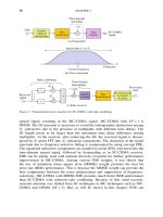
The main technical impacts of these harmonisation activities were the change of UTRA
FDD and TDD mode chip rate from 4.096 Mcps to 3.84 Mcps and the inclusion of a
common pilot for UTRA FDD. The work in 3GPP2 focused on the MC mode, and the DS
mode from cdma2000 was abandoned. Eventually, the work in 3GPP2 resumed on the
1.28 Mcps evolution and development of the MC mode has been stopped. The result is that
globally there is only one Direct Spread (DS) wideband CDMA standard, WCDMA.
4.10 IMT-2000 Process in ITU
In the ITU, recommendations have been developed for third generation mobile commu-
nications systems, the ITU terminology being called IMT-2000 [10], formerly FPLMTS. In
the ITU-R, ITU-R TG8/1 has worked on the radio-dependent aspects, while the radio-
independent aspects have been covered in ITU-T SG11.
In the radio aspects, ITU-R TG8/1 received a number of different proposals during the
IMT-2000 candidate submission process. In the second phase of the process, evaluation
results were received from the proponent organisations as well as from the other evaluation
groups that studied the technologies. During the first half of 1999 recommendation
IMT.RKEY, which describes the IMT-2000 multimode concept, was created.
70 WCDMA for UMTS
The ITU-R IMT-2000 process was finalised at the end of 1999, when the detailed
specification (IMT-RSCP) was created and the radio interface specifications were approved
by ITU-R [11]. The detailed implementation of IMT-2000 will continue in the regional
standards bodies. The ITU-R process has been an important external motivation and timing
source for IMT-2000 activities in regional standards bodies. The requirements set by ITU for
an IMT-2000 technology have been reflected in the requirements in the regional standar ds
bodies, for example in ETSI UMTS 21.01 [5], in order for the ETSI submission to fulfil the
IMT-2000 requirements. The ITU-R interaction between regional standardisation bodies in
the IMT-2000 process is reflected in Figure 4.5.
The ITU-R IMT-2000 grouping, with TDMA- and CDMA-based groups, is illustrated in
Figure 4.6. The UTRA FDD (WCDMA) and cdma2000 are each part of the CDMA
Figure 4.5. ITU-R IMT-2000 grouping
Figure 4.6. Relationship of ITU-R to the regional standards bodies
Background and Standardisation of WCDMA 71
interface, as CDMA Direct Spread and CDMA Multicarrier respectively. UWC-136 and
DECT are part of the TDMA-based interface in the concept, as TDMA Single Carrier and
TDMA Multicarrier respectively. The TDD part in CDMA consists of UTRA TDD from
3GPP and TD-SCDMA from CWTS. For the FDD part in the CDMA interface, harmonisa-
tion has been completed, and the harmonisation process for the CDMA TDD modes within
3GPP resulted in the 1.28 Mcps TDD being included in the 3GPP Release 4 specifications,
completed 03/2001.
4.11 Beyond 3GPP Release ’99
Upon completion of the Release ’99 specifications, work will concentrate on specify ing new
features as well as making the necessary corrections to Release 1999. Typically such
corrections arise as implementation proceeds and test systems are updated to include the
latest changes in the specifications. As experience in various forums has shown, a major step
forward in system capabilities with many new features requires a phasing-in period for the
specifications. Fortunately, the main functions have been verified in the various test systems
in operation since 1995, but only the actual implementation will reveal any errors and
inconsistencies in the fine detail of the specifications.
In 3GPP the next version of the specifications was originally considered as Release 2000,
but in the meantime the Release naming was adjusted, so that the next release in March 2001
was called Release 4. Release 4 cont ained only minor adjustments with respect to Release
1999. Bigger items that were included in Release 5 were High-Speed Downlink Packet
Access (HSDPA) and IP-based transport layer, see Chapters 11 and 5 respectively. Release 5
was completed 03/2002 for the WCDMA radio aspects. Release ’99 specifications have a
version number starting with 3 while Release 4 and 5 specifications have version numbers
starting logically with 4 and 5 respectively.
On the TDD side, the narrowband (1.28 Mcps) TDD mode originally from CWTS (China)
was included in 3GPP Release 4. The 1.28 Mcps UTRA TDD mode, or TD-SCDMA, is
covered in Chapter 13.
Besides the IP-based transport option in Release 5 the protocols developed by the Int ernet
Engineering Task Force (IETF) have also influenced the WCDMA specifications. Release 4
specifications contain robust IP header compression suitable for cellular transmission to
enable an efficient Voice over IP (VoIP) service.
The next step in the evolution is Release 6, which now has first versions of the
specifications available (RAN side), but all features are currently scheduled to be available
by 2H/2004. For Release 6, work has been done, e.g., on Multimedia Broadcast Multicast
Service (MBMS), feasibility of HSDPA-related enhancements for uplink, radio resource
management supporting measurements for beamforming and on other features to enhance
the system performance .
Work will then continue for Release 7. The exact timing for Release 7 has not been fixed
yet, but it is expected to be towards the end of 2005. Which Release a particular feature will
end up in will be determined only once the feature is mature enough to enable a change
request to be written for the specifications.
72 WCDMA for UMTS
References
[1] Pajukoski, K. and Savusalo, J., ‘Wideband CDMATest System’, Proc. IEEE Int. Conf. on Personal
Indoor and Mobile Radio Communications, PIMRC’97, Helsinki, Finland, 1–4 September 1997,
pp. 669–672.
[2] Nikula, E., Toskala, A., Dahlman, E., Girard, L. and Klein, A., ‘FRAMES Multiple Access for
UMTS and IMT-2000’, IEEE Personal Communications Magazine, April 1998, pp. 16–24.
[3] Klein, A., Pirhonen, R., Sko
¨
ld, J. and Suoranta, R., ‘FRAMES Multiple Access Mode 1 –
Wideband TDMA with and without Spreading’, Proc. IEEE Int. Conf. on Personal Indoor and
Mobile Radio Communications, PIMRC’97, Helsinki, Finland, 1–4 September 1997, pp. 37–41.
[4] Ovesjo
¨
, F., Dahlman, E., Ojanpera
¨
, T., Toskala, A. and Klein, A., ‘FRAMES Multiple Access Mode
2 – Wideband CDMA’, Proc. IEEE Int. Conf. on Personal Indoor and Mobile Radio Commu-
nications, PIMRC’97, Helsinki, Finland, 1–4 September 1997, pp. 42–46.
[5] Universal Mobile Telecommunications System (UMTS), Requirements for the UMTS Terrestrial
Radio Access System (UTRA), ETSI Technical Report, UMTS 21.01 version 3.0.1, November
1997.
[6] Universal Mobile Telecommunications System (UMTS), Selection Procedures for the Choice of
Radio Transmission Technologies of the UMTS, ETSI Technical Report, UMTS 30.03 version
3.1.0, November 1997.
[7] Universal Mobile Telecommunications System (UMTS), UMTS Terrestrial Radio Access System
(UTRA) Concept Evaluation, ETSI Technical Report, UMTS 30.06 version 3.0.0, December 1997.
[8] ETSI Press Release, SMG Tdoc 40/98, ‘Agreement Reached on Radio Interface for Third
Generation Mobile System, UMTS’, Paris, France, January 1998.
[9]
[10] />[11] ITU Press Release, ITU/99-22, ‘IMT-2000 Radio Interface Specifications Approved in ITU
Meeting in Helsinki’, 5 November 1999.
Background and Standardisation of WCDMA 73
5
Radio Access Network Architecture
Fabio Longoni, Atte La
¨
nsisalmi and Antti Toskala
5.1 System Architecture
This chapter gives a wide overview of the UMTS system architecture, including an
introduction to the logical network elements and the interfaces. The UMTS system utilises
the same well-known architecture that has been used by all main second generation systems
and even by some first generation systems. The reference list contains the related 3GPP
specifications.
The UMTS system consists of a number of logical network elements that each has a
defined functionality. In the standards, network elements are defined at the logical level, but
this quite often results in a similar physical implementati on, especially since there are a
number of open interfaces (for an interface to be ‘open’, the requirement is that it has been
defined to such a detailed level that the equipment at the endpoints can be from two different
manufacturers). The network elements can be grouped based on similar functionality, or
based on which sub-network they belong to.
Functionally the network elements are grouped into the Radio Access Network (RAN,
UMTS Terrestrial RAN ¼ UTRAN) that handles all radio-related functionality, and the Core
Network, which is responsible for switching and routing calls and data connections to
external networks. To complete the system, the User Equipment (UE) that interfaces with the
user and the radio interface is defined. The high-level system arch itecture is shown in
Figure 5.1.
From a specification and standardisation point of view, both UE and UTRAN consist of
completely new protocols, the design of which is based on the needs of the new WCDMA
radio technology. On the contrary, the definition of Core Network (CN) is adopted from
GSM. This gives the system with new radio technology a global base of known and rugged
CN technology that accelerates and facilitates its introduction, and enables such competitive
advantages as global roaming.
Another way to group UMTS network elements is to divide them into sub-networks. The
UMTS system is modular in the sense that it is possible to have several network elements of
the same type. In principle, the minimum requirement for a fully featured and operational
WCDMA for UMTS, third edition. Edited by Harri Holma and Antti Toskala
# 2004 John Wiley & Sons, Ltd ISBN: 0-470-87096-6
network is to have at least one logical network element of each type (note that some features
and consequently some network elements are optional). The possibility of having several
entities of the same type allows the division of the UMTS system into sub-networks that are
operational either on their own or together with other sub-networks, and that are distin-
guished from each other with unique identities. Such a sub-network is called a UMTS
PLMN (Public Land Mobile Network). Typically one PLMN is operated by a single
operator, and is connected to othe r PLMNs as well as to other types of network, such as
ISDN, PSTN, the Internet, and so on. Figure 5.2 shows elements in a PLMN and, in order to
illustrate the connections, also external networks.
The UTRAN architecture is presented in Section 5.2. A short introduction to all the
elements is given below.
The UE consists of two parts:
The Mobile Equipment (ME) is the radio terminal used for radio communication over the
Uu interface.
The UMTS Subscriber Identity Module (USIM) is a smartcard that holds the subscriber
identity, performs authentication algorithms, and stores authentication and encryption
keys and some subscription information that is needed at the terminal.
UTRAN also consists of two distinct elements:
The Node B converts the data flow between the Iub and Uu interfaces. It also participates
in radio resource management. (Note that the term ‘Node B’ from the corresponding
Figure 5.1. UMTS high-level system architecture
Figure 5.2. Network elements in a PLMN
76 WCDMA for UMTS
3GPP specifications is used throughout Chapter 5. The more generic term ‘Base Station’
used elsewhere in this boo k means exactly the same thing.)
The Radio Network Controller (RNC) owns and controls the radio resources in its
domain (the Node Bs connected to it). RNC is the service access point for all services
UTRAN provides the CN, for example, management of connections to the UE.
The main elements of the GSM CN (there are other entities not shown in Figure 5.2, such
as those used to provide IN services) are as follows:
HLR (Home Location Register) is a database located in the user’s home system that
stores the master copy of the user’s service profile. The service profile consists of, for
example, information on allowed services, forbidden roaming areas, and supplementary
service information such as status of call forwarding and the cal l forwarding number. It is
created when a new user subscribes to the system, and remains stored as long as the
subscription is active. For the purpose of routing incoming transactions to the UE (e.g.
calls or short messages), the HLR also stores the UE location on the level of MSC/VLR
and/or SGSN, i.e. on the level of the serving system.
MSC/VLR (Mobile Services Switching Centre/Visitor Location Register) is the switch
(MSC) and database (VLR) that serves the UE in its current location for Circuit Switched
(CS) service s. The MSC function is used to switch the CS transactions, and the VLR
function holds a copy of the visiting user’s service profile, as well as more precise
information on the UE’s location within the serving system. The part of the network that
is accessed via the MSC/VLR is often referred to as the CS domain. MSC also has a role
in the early UE handling, as discussed in Chapter 7.
GMSC (Gateway MSC) is the switch at the point where UMTS PLMN is connected to
external CS networks. All incoming and outgoing CS connections go through GMSC.
SGSN (Serving GPRS (General Packet Radio Service) Support Node) functionality is
similar to that of MSC/VLR but is typically used for Packet Switched (PS) services. The
part of the network that is accessed via the SGSN is often referred to as the PS domain.
Similar to MSC, SGSN support is needed for the early UE handling operation, as covered
in Chapter 7.
GGSN (Gateway GPRS Support Node) functionality is close to that of GMSC but is in
relation to PS services.
The external networks can be divided into two groups:
CS networks. These provide circuit-switched connections, like the existing telephony
service. ISDN and PSTN are examples of CS networks.
PS networks. These provide connections for packet data services. The Internet is one
example of a PS network.
The UMTS standard s are structured so that internal functionality of the networ k elements
is not specified in detail. Instead, the interfaces between the logical network elements have
been defined. The following main open interfaces are specified:
Radio Access Network Architecture 77
Cu interface. This is the electrical interface between the USIM smartcard and the ME.
The interface follows a standard format for smartcards.
Uu interface. This is the WCDMA radio interface, which is the subject of the main part
of this book. The Uu is the interface through which the UE accesses the fixed part of the
system, and is therefore probably the most important open interface in UMTS. There are
likely to be many more UE manufacturers than manufacturers of fixed network elements.
Iu interface. This connects UTRAN to the CN and is introduced in detail in Section 5.4.
Similarly to the corresponding interfaces in GSM, A (Circuit Switched) and Gb (Packet
Switched), the open Iu interface gives UMTS operators the possibility of acquiring
UTRAN and CN from different manufacturers. The enabled competition in this area has
been one of the success factors of GSM.
Iur interface. The open Iur interface allows soft handover between RNCs from different
manufacturers, and therefore complements the open Iu interface. Iur is described in more
detail in Section 5.5.1.
Iub interface. The Iub connects a Node B and an RNC. UMTS is the first commercial
mobile telephony system where the Controller–Base Station interface is standardised as a
fully open interface. Like the other open interfaces, open Iub is expected to further
motivate competition between manufacturers in this area. It is likely that new manu-
facturers concentrating exclusively on Node Bs will enter the market.
5.2 UTRAN Architecture
UTRAN architecture is highlighted in Figure 5.3.
UTRAN consists of one or more Radio Network Sub-systems (RNS). An RNS is a sub-
network within UTRAN and consists of one Radio Network Controller (RNC) and one or
more Node Bs. RNCs may be connected to each other via an Iur interface. RNCs and Node
Bs are connected with an Iub interface.
Before entering into a brief description of the UTRAN network elements (in this section)
and a more extensive description of UTRA N interfaces (in the following sections), we
Figure 5.3. UTRAN architecture
78 WCDMA for UMTS
present the main characteristics of UTRAN that have also been the main requirements for
the design of the UTRAN architecture, functions and protocols. These can be summarised in
the following points:
Support of UTRA and all the related functionality. In particular, the major impact on the
design of UTRAN has been the requirement to support soft handover (one terminal
connected to the network via two or more active cells) and the WCDMA-specific Radio
Resource Management algorithms.
Maximisation of the commonalities in the handling of packet-switched and circuit-
switched data, with a unique air interface protocol stack and with the use of the same
interface for the connection from UTRAN to both the PS and CS domains of the core
network.
Maximisation of the common alities with GSM, when possible.
Use of the ATM transport as the main transport mechanism in UTRAN.
Use of the IP-based transport as the alternative transport mechanism in UTRAN from
Release 5 onwards.
5.2.1 The Radio Network Controller
The RNC (Radio Network Controller) is the network element responsible for the control of
the radio resources of UTRAN. It interfaces the CN (normally to one MSC and one SGSN)
and also terminates the RRC (Radio Resource Control) protocol that defines the messages
and procedures between the mobile and UTRAN. It logically corresponds to the GSM
BSC.
5.2.1.1 Logical Role of the RNC
The RNC controlling one Node B (i.e. terminating the Iub interface towards the Node B)
is indicated as the Controlling RNC (CRNC) of the Node B. The Controlling RNC is
responsible for the load and congestion control of its own cells, and also executes the
admission control and code allocation for new radio links to be established in those
cells.
In case one mobile–UTRAN connection uses resources from more than one RNS (see
Figure 5.4), the RNCs involved have two separat e logical roles (with respect to this mobile–
UTRAN connection):
Serving RNC. The SRNC for one mobile is the RNC that terminates both the Iu link for
the transport of user data and the corresponding RANAP signalling to/from the core
network (this connection is referred to as the RANAP connection). The SRNC also
terminates the Radio Resource Control Signalling, that is the signalling protocol between
the UE and UTRAN. It performs the L2 processing of the data to/from the radio
interface. Basic Radio Resource Management operations, such as the mapping of Radio
Access Bearer parameters into air interface transport channel parameters, the handover
decision, and outer loop power control, are executed in the SRNC. The SRNC may also
(but not always) be the CRNC of some Node B used by the mobile for connection with
UTRAN. One UE connec ted to UTRAN has one and only one SRNC.
Radio Access Network Architecture 79
Drift RNC. The DRN C is any RNC, other than the SRNC, that controls cells used by the
mobile. If needed, the DRNC may perform macrodiversity combining and splitting. The
DRNC does not perform L2 processing of the user plane data, but routes the data
transparently between the Iub and Iur interfaces, except when the UE is using a common
or shared transport channel. One UE may have zero, one or more DRNCs.
Note that one physical RNC normally contains all the CRNC, SRNC and DRNC
functionality.
5.2.2 The Node B (Base Station)
The main function of the Node B is to perform the air interface L1 processing (channel
coding and interleaving, rate adaptation, spreading, etc.). It also performs some basic Radio
Resource Management operations such as the inner loop power control. It logically
corresponds to the GSM Base Station. The enigmatic term ‘Node B’ was initially adopted
as a temporary term during the standardisation process, but then never changed.
The logical model of the Node B is described in Section 5.5.2.
5.3 General Protocol Model for UTRAN Terrestrial Interfaces
5.3.1 General
Protocol structures in UTRAN terrestrial interfaces are designed according to the same
general protocol model. This model is shown in Figure 5.5. The structure is based on the
principle that the layers and plan es are logically independent of each other and, if needed,
parts of the protocol structure may be changed in the future while other parts remain intact.
5.3.2 Horizontal Layers
The protocol structure consists of two main layers, the Radio Network Layer and the
Transport Network Layer. All UTRAN-related issues are visible only in the Radio Network
Layer, and the Transport Network Layer represe nts standard transport technology that is
selected to be used for UTRAN but without any UTRAN-specific changes.
Figure 5.4. Logical role of the RNC for one UE UTRAN connection. The left-hand scenario shows
one UE in inter-RNC soft handover (combining is performed in the SRNC). The right-hand scenario
represents one UE using resources from one Node B only, controlled by the DRNC
80 WCDMA for UMTS
5.3.3 Vertical Planes
5.3.3.1 Control Plane
The Control Plane is used for all UMTS-specific control signalling. It includes the
Application Protocol (i.e. RANAP in Iu, RNSAP in Iur and NBAP in Iub), and the
Signalling Bearer for tran sporting the Application Protocol messages.
The Application Protocol is used, among other things, for setting up bearers to the UE (i.e.
the Radio Access Bearer in Iu and subsequently the Radio Link in Iur and Iub). In the three-
plane structure the bearer parameters in the Application Protocol are not directly tied to the
User Plane technology, but rather are general bearer parameters.
The Signalling Bearer for the Application Protocol may or may not be of the same type as
the Signalling Bearer for the ALCAP. It is always set up by O&M actions.
5.3.3.2 User Plane
All information sent and received by the user, such as the coded voice in a voice call or the
packets in an Internet connection, are transported via the User Plane. The User Plane
includes the Data Stream(s), and the Data Bearer(s) for the Data Stream(s). Each Data
Stream is characterised by one or more frame protocols specified for that interface.
5.3.3.3 Transport Network Control Plane
The Transport Network Control Plane is used for all control signalling within the Transport
Layer. It does not include any Radio Network Layer information. It includes the ALCAP
protocol that is needed to set up the transport bearers (Data Bearer) for the User Plane. It also
includes the Signalling Bearer needed for the ALCAP.
The Transport Network Control Plane is a plane that acts between the Control Plane and
the User Plane. The introduction of the Transport Network Control Plane makes it possible
Figure 5.5. General protocol model for UTRAN terrestrial interfaces
Radio Access Network Architecture 81
for the Application Protocol in the Radio Network Control Plane to be completely
independent of the technology selected for the Data Bearer in the User Plane.
When the Transport Network Control Plane is used, the transport bearers for the Data
Bearer in the User Plane are set up in the following fashion. First there is a signalling
transaction by the Application Protocol in the Control Plane, which triggers the set-up of the
Data Bearer by the ALCAP protocol that is specific for the User Plane technology.
The independence of the Control Plane and the User Plane assumes that an ALCAP
signalling transaction takes place. It should be noted that ALCAP might not be used for all
types of Data Bearer. If there is no ALCAP signalling transaction, the Transport Network
Control Plane is not needed at all. This is the case when it is enough to simply select the user
plane resources, e.g. selecting end point addresses for IP transport or selecting a precon-
figured Data Bearer. It should also be note d that the ALCAP protocol(s) in the Transport
Network Control Plane is/are not used for setting up the Signalling Bearer for the
Application Protocol or for the ALCAP during real-time operation.
The Signalling Bearer for the ALCAP may or may not be of the same type as that for the
Application Protocol. The UMTS specifications assume that the Signalling Bearer for
ALCAP is always set up by O&M actions, and do not specify this in detail.
5.3.3.4 Transport Network User Plane
The Data Bearer(s) in the User Plane, and the Signalling Bearer(s) for the Application
Protocol, also belong to the Transport Network User Plane. As described in the previous
section, the Data Bearers in the Transport Network User Plane are directly controlled by the
Transport Network Control Plane during real-time operation, but the control actions required
for setting up the Signalling Bearer(s) for the Application Protocol are considered O&M
actions.
5.4 Iu, The UTRAN–CN Interface
The Iu interface connects UTRAN to CN. Iu is an open interface that divides the system into
radio-specific UTRAN and CN which handles switching, routing and service control. As can
be seen from Figure 5.3, the Iu can have two main different instances, which are Iu CS (Iu
Circuit Switched) for connecting UTRAN to Circuit Switched (CS) CN, and Iu PS (Iu Packet
Switched) for connecting UTRAN to Packet Switched (PS) CN. The additional third
instance of Iu, the Iu BC (Iu Broadcast), has been defined to support Cell Broadcast
Services (See Section 5.4.5). Iu BC is used to connect UTRAN to the Broadcast domain of
the Core Network. The Iu BC interface is not shown in Figure 5.3. The original design goal
in the standardisation was to develop only one Iu interface, but then it was realised that fully
optimised User Plane transport for CS and PS services can only be achieved if different
transport technologies are allowed. Consequently, the Transport Network Control Plane is
different. One of the main design guidelines has still been that the Control Plane should be
the same for Iu CS and Iu PS, and the differences are minor.
5.4.1 Protocol Structure for Iu CS
The Iu CS overall protocol structure is depicted in Figure 5.6. The three planes in the Iu
interface share a common ATM (Asynchronous Transfer Mode) transport which is used for
all planes. The physical layer is the interface to the physical medium: optical fibre, radio link
82 WCDMA for UMTS
or copper cable. The physical layer implementation can be selected from a variety of
standard off-the-shelf transmission technologies, such as SONET, STM1, or E1.
5.4.1.1 Iu CS Control Plane Protocol Stack
The Control Plane protocol stack consists of RANAP, on top of Broadband (BB) SS7
(Signalling System #7) protocols. The applicable layers are the Signalling Connection
Control Part (SCCP), the Message Transfer Part (MTP3-b) and SAAL-NNI (Signalling ATM
Adaptation Layer for Network to Network Interfaces). SAAL-NNI is further divided into
Service Specific Coordinat ion Function (SSCF), Service Specific Connection Oriented
Protocol (SSCOP) and ATM Adaptation Layer 5 (AAL) layers. SSCF and SSCOP layers
are specifically designed for sign alling transport in ATM networks, and take care of such
functions as signalling connection management. AAL5 is used for segmenting the data to
ATM cells.
5.4.1.2 Iu CS Transport Netw ork Control Plane Protocol Stack
The Transport Network Control Plane protocol stack consists of the Signalling Protocol for
setting up AAL2 connections (Q.2630.1 and adaptation layer Q.2150.1), on top of BB SS7
protocols. The applicable BB SS7 are those described above without the SCCP layer.
5.4.1.3 Iu CS User Plane Protocol Stack
A dedicated AAL2 connection is rese rved for each individual CS service. The Iu User Plane
Protocol residing directly on top of AAL2 is described in more detail in Section 5.4.4.
Figure 5.6. Iu CS protocol structure
Radio Access Network Architecture 83
5.4.2 Protocol Structure for Iu PS
The Iu PS protocol structure is depicted in Figure 5.7. Again, a common ATM transport is
applied for both User and Control Plane. Also the physical layer is as specified for Iu CS.
5.4.2.1 Iu PS Control Plane Protocol Stack
The Control Plane protocol stack again consists of RANAP, and the same BB SS7-based
signalling bearer as described in Section 5.4.1.1. Also, as an alternative, an IP-based
signalling bear er is specified. The SCCP layer is also used commonly for both. The IP-
based signalling bearer consists of M3UA (SS7 MTP3 – User Adaptation Layer), SCTP
(Simple Control Transmission Protocol), IP (Internet Protocol), and AAL5 which is common
to both alternatives. The SCTP layer is specifically designed for signalling transport in the
Internet. Specific adaptation layers are specified for different kinds of signalling protocol,
such as M3UA for SS7-based signalling.
5.4.2.2 Iu PS Transport Network Control Plane Protocol Stack
The Transport Network Control Plane is not appl ied to Iu PS. The setting up of the GTP
tunnel requires only an identifier for the tunnel, and the IP addresses for both directions, and
these are already included in the RANAP RAB Assignment messages. The same information
elements that are used in Iu CS for addressing and identifying the AAL2 signalling are used
for the User Plane data in Iu CS.
Figure 5.7. Iu PS protocol structure
84 WCDMA for UMTS
5.4.2.3 Iu PS User Plane Protocol Stack
In the Iu PS User Plane, multiple packet data flows are multiplexed on one or several AAL5
PVCs. The GTP-U (User Plane part of the GPRS Tunnelling Protocol) is the multiplexing
layer that provides identities for individual packet data flow. Each flow uses UDP
connectionless transport and IP addressing.
5.4.3 RANAP Protocol
RANAP is the signalling protocol in Iu that contains all the control information specified for
the Radio Network Layer. The functionality of RANAP is implemented by various RANAP
Elementary Procedures. Each RANAP function may require the execution of one or more
EPs. Each EP consists of either just the request message (class 2 EP), the request and
response message pair (class 1 EP), or one request message and one or more response
messages (class 3 EP). The following RANAP functions are defined:
Relocation. This function handles both SRNS Relocation and Hard Handover, including
the inter-system case to/from GSM:
– SRNS Relocation: the serving RNS functionality is relocated from one RNS to another
without changing the radio resources and without interrupting the user data flow. The
prerequisite for SRNS relocation is that all Radio Links are already in the same DRNC
that is the target for the relocation.
– Inter-RNS Hard Handover: used to relocate the serving RNS functionality from one
RNS to anot her and to change the radio resources correspondingly by a hard handover
in the Uu interface. The prerequisite for Hard Handover is that the UE is at the border
of the source and target cells.
RAB (Radio Access Bearer) Management. This function combines all RAB handling:
– RAB Set-up, including the possibility for queuin g the set-up;
– modification of the characteristics of an existing RAB;
– clearing an existing RAB, including the RAN-initiated case.
Iu Release. Releases all resources (Signalling link and U-Plane) from a given instance of
Iu related to the specified UE. Also includes the RAN-initiated case.
Reporting Unsuccessfully Transmitted Data. This function allows the CN to update its
charging records with information from UTRAN if part of the data sent was not
successfully sent to the UE.
Common ID management. In this function the permanent identification of the UE is sent
from the CN to UTRAN to allow paging coordination from possibly two different CN
domains.
Paging. This is used by CN to page an idle UE for a UE terminating service request,
such as a voice call. A paging message is sent from the CN to UTRAN with the UE
common identification (permanent Id) and the paging area. UTRAN will either use an
existing sign alling connection, if one exists, to send the page to the UE or broadcast the
paging in the requested area.
Management of tracing. The CN may, for operation and maintenance purposes, request
UTRAN to start recording all activity related to a specific UE–UTRA N connection.
Radio Access Network Architecture 85
UE–CN signalling transfer. This functionality provides transparent transfer of UE–CN
signalling messages that are not interpreted by UTRAN in two cases:
– Transfer of the first UE message from UTRAN to UE: this may be, for example, a
response to paging, a request of a UE-originated call, or just registration to a new area.
It also initiates the signalling connection for the Iu.
– Direct Transfer: used for carrying all consecutive signalling messages over the Iu
signalling connection in both the uplink and downlink directions.
Security Mode Control. This is used to set the ciphering or integrity check ing on or off.
When ciphering is on, the signalling and user data connections in the radio interface are
encrypted with a secret key algorithm. When integrity checking is on, an integrity
checksum, further secured with a secret key, is added to some or all of the Radio
Interface signalling messages. This ensures that the communication partner has not
changed, and the content of the information has not been altered.
Management of overload. This is used to control the load over the Iu interface against
overload due, for example, to processor overload at the CN or UTRAN. A simple
mechanism is applied that allows stepwise reduction of the load and its stepwise
resumption, triggered by a timer.
Reset. This is used to reset the CN or the UTRAN side of the Iu interface in error
situations. One end of the Iu may indicate to the other end that it is recovering from a
restart, and the other end can remove all previously established connections.
Location Reporting. This functionality allows the CN to receive information on the
location of a given UE. It include s two elementary procedures, one for controlling the
location reporting in the RNC and the other to send the actual report to the CN.
5.4.4 Iu User Plane Protocol
The Iu User Plane protocol is in the Radio Network Layer of the Iu User Plane. It has been
defined to be, as much as possible, independent of the CN domain that it is used for. The
purpose of the User Plane protocol is to carry user data related to RABs over the Iu interface.
Each RAB has its own instanc e of the protocol. The protocol performs either a fully
transparent operation, or framing for the user data segments and some basi c control
signalling to be used for initialisation and online cont rol. Based on these cases, the protocol
has two modes:
Transparent Mode. In this mode of operation the protocol does not perform any framing
or control. It is applied for RABs that do not require such features but that assume fully
transparent operation.
Support Mode for predefined SDU sizes. In this mode the User Plane performs framing
of the user data into segments of predefined size. The SDU sizes typically correspond to
AMR (Adaptive Multirate Codec) speech frames, or to the frame sizes derived from the
data rate of a CS data call. Also, control procedures for initialisation and rate control are
defined, and a functionality is specified for indicating the quality of the frame based, for
example, on CRC from the radio interface.
86 WCDMA for UMTS
5.4.5 Protocol Structure of Iu BC, and the SABP Protocol
The Iu BC [2] interface connects the RNC in UTRAN with the broadcast domain of the Core
Network, namely with the Cell Broadcast Centre. It is used to define the Ce ll Broadcast
information that is transmitted to the mobil e user via the Cell Broadcast Service (e.g. name
of city/region visualised on the mobile phone display). Note that this shall not be confused
with the UTRAN or Core Network information broadcast on the broadcast common control
channel. Iu BC is a control plane only interface. The protocol structure of Iu BC is shown in
Figure 5.8.
5.4.5.1 SABP Protocol
The Service Area Broadcast Protocol (SABP) [8] provides the capability for the Cell
Broadcast Centre in the CN to define, modify and remove cell broadcast messages from the
RNC. RNC uses them and the NBAP protocol and RRC signalling to transfer such messages
to the mobile. The SABP has the following functions:
Message Handling. This function is responsible for the broadcast of new messages,
amendment of existing broadcast message s and prevention of the broadcasting of specific
messages.
Figure 5.8. Iu BC protocol structure
Radio Access Network Architecture 87
Load Handling. This function is responsible for determining the loading of the broadcast
channels at any particular point in time.
Reset. This function permits the CBC to end broadcasting in one or more Service Areas.
5.5 UTRAN Internal Interfaces
5.5.1 RNC–RNC Interface (Iur Interface) and the RNSAP Signalling
The protocol stack of the RNC to RNC interface (Iur interface) is shown in Figure 5.9.
Although this interface was initially designed in order to support the inter-RNC soft
handover (shown on the left-hand side of Figure 5.4), more features were added during
the development of the standard and currently the Iur interface provides four distinct
functions:
1. Support of basic inter-RNC mobility;
2. Support of Dedicated Channel traffic;
Figure 5.9. Release ’99 protocol stack of the Iur interface. As for the Iu interface, two options are
possible for the transport of the RNSAP signalling: the SS7 stack (SCCP and MTP3b) and the new
SCTP/IP-based transport. Two User Plane protocols are defined (DCH: dedicated channel; CCH:
common channel).
88 WCDMA for UMTS
3. Support of Common Channel traffic;
4. Support of Global Resource Management.
For this reason the Iur signalling protocol itself (RNSAP, Radio Network System
Application Part) is divided into four different modules (intended as groups of procedures).
In general, it is possible to implement only part of the four Iur modules between two Radio
Network Controllers, according to the operator’s need.
5.5.1.1 Iur1: Support of the Basic Inter-RNC Mobility
This functionality requires the basic module of RNSAP signalling as described in [12]. This
first brick for the construction of the Iur interfaces provides by itself the functionality needed
for the mobility of the user between the two RNCs, but does not support the exchange of any
user data traffic. If this module is not implemented, the Iur interface as such does not exist,
and the only way for a user connected to UTRAN via the RNS1 to utilise a cell in RNS2 is to
disconnect itself temporarily from UTRAN (release the RRC connection).
The functions offered by the Iur basic module include:
Support of SRNC relocation.
Support of inter-RNC cell and UTRAN registration area update.
Support of inter-RNC packet paging.
Reporting of protocol errors.
Since this functionality does not involve user data traffic across Iur, the User Plane and the
Transport Network Control Plane protocols are not needed.
5.5.1.2 Iur2: Support of Dedicated Channel Traffic
This functionality requires the Dedicated Channel module of RNSAP signalling and allows
the dedicated and shared channel traffic between two RNCs. Even if the initial need for this
functionality is to support the inter-RNC soft handover state, it also allows the anchoring of
the SRNC for all the time the user is utilising dedicated channels (dedicated resources in the
Node B), commonly for as long as the user has an active connection to the circuit-switched
domain.
This functionality requires also the User Plane Frame Protocol for the dedicated and
shared channel, plus the Transport Network Control Plane protocol (Q.2630.1) used for the
set-up of the transport connections (AAL2 connections). Each dedicated channel is conveyed
over one transport connection, except the coordinated DCH used to obtain unequal error
protection in the air interface.
The Frame Protocol for dedicated channels, in short DCH FP [16], defines the structure of
the data frames carrying the user data and the control frames used to exchange measure-
ments and control information. For this reason, the Frame Protocol also specifies simple
messages and procedures. The user data frames are normally routed transparently through
the DRNC; thus the Iur frame protocol is also used in Iub and referred to as Iur/Iub DCH FP.
The user plane procedure for the shared channel is described in the Frame Protocol for the
common channel in the Iur interface, in short Iur CCH FP [14].
Radio Access Network Architecture 89
The functions offered by the Iur DCH module are:
Establishment, modification and release of the dedicated and shared channel in the
DRNC due to handovers in the dedicated channel state.
Set-up and release of dedicated transport connections across the Iur interface.
Transfer of DCH Transport Blocks between SRNC and DRNC.
Management of the radio links in the DRNS via dedicated measurement report
procedures, power setting procedures and compress mode control procedures.
5.5.1.3 Iur3: Support of Common Channel Traffic
This functionality allows the handling of common channel (i.e. RACH, FACH and CPCH)
data streams across the Iur interface. It requires the Common Transport Channel module of
the RNSAP protocol and the Iur Common Transport Channel Frame Protocol (in short, CCH
FP). The Q.2630.1 signalling protocol of the Transport Network Control Plane is also needed
if signalled AAL2 connections are used.
If this functionality is not implemented, every inter-RNC cell update always triggers an
SRNC relocation, i.e. the serving RNC is always the RNC controlling the cell used for
common or shared channel transport.
The identification of the benefits of this feature caused a long debate in the relevant
standardisation body. On the one hand, this feature allows the implementation of the total
anchor RNC concept, avoiding the SRNC relocation procedure (via the CN); on the other
hand, it requires the splitting of the Medium Access Control layer functionality into two
network elements, generating inefficiency in the utilisation of the resources and complexity
in the Iur interface. The debate could not reach an agreement, thus the feature is supported
by the standard but is not essential for the operation of the system.
The functions offered by the Iur common transport channel module are:
Set-up and release of the transport connection across the Iur for common channel data
streams.
Splitting of the MAC layer between the SRNC (MAC-d) and the DRNC (MAC-c). The
scheduling for DL data transmission is performed in the DRNC.
Flow control between the MAC-d and MAC-c.
5.5.1.4 Iur4: Support of Global Resource Management
This functionality provides signalling to support enhanced radio resource management and
O&M features across the Iur interface. It is implemented via the global module of the
RNSAP protocol, and does not require any User Plane protocol, since there is no
transmission of user data across the Iur interface. The function is considered optional.
This function has been introduced in subsequent releases for the support of common radio
90 WCDMA for UMTS
resource management between RNCs, advanced positioning methods and Iur optimisation
purposes.
The functions offered by the Iur global resource module are:
Transfer of cell information and measurements between two RNCs.
Transfer of positioning parameters between controller.
Transfer of Node B timing inform ation between two RNCs.
5.5.2 RNC–Node B Interface and the NBAP Signalling
The protocol stack of the RNC–Node B interface (Iub interface) is shown, with the typical
triple plane notation, in Figure 5.10.
In order to understand the structure of the interface, it is neces sary to briefly introduce the
logical model of the Node B, depicted in Figure 5.11. This consists of a common control port
(a common signalling link) and a set of traffic terminati on points, each controlled by a
dedicated control port (dedicated signalli ng link). One traffic termination point controls a
Figure 5.10. Release ’99 protocol stack of the Iub interface. This is similar to the Iur interface
protocol, the main difference being that in the Radio Network and Transport Network Control Planes
the SS7 stack is replaced by the simpler SAAL-UNI as signalling bearer. Note also that the SCTP/IP
option is not present here
Radio Access Network Architecture 91