A Professional’s Guide to Data Communication in a TCP/IP World phần 3 pptx
Bạn đang xem bản rút gọn của tài liệu. Xem và tải ngay bản đầy đủ của tài liệu tại đây (240.31 KB, 27 trang )
•
Combines user’s data with generic function software to create a user’s data
block identified as information retrieval, file transfer, and mail.
•
Encapsulates the user’s data block with a header (application header, AH) and
identifies the source port from which it is sent, and to which any reply must be
addressed.
•
Passes the application protocol data unit (APDU) to the transport layer.
When receiving, the application layer:
•
Removes the application header from the APDU to leave the user’s data block.
•
Provides any processing required to complete the transaction.
•
Passes the user’s data to the user’s application.
•
Confirms that the process is completed.
2.4.2 Transport Layer
Two modes of operation are possible in the transport layer. The header may support
a simple, connectionless procedure called User Datagram Protocol (UDP), or may
support a connection-oriented procedure called Transmission Control Protocol
(TCP). The transport layer PDU is called a segment or message. When sending in the
connectionless mode, the transport layer:
•
Accepts the APDU from the application layer.
•
Records both source and destination ports.
•
Calculates a checksum and transmits the ones complement.
•
Encapsulates the APDU with a header (TH) containing this information.
•
Passes the TPDU to the Internet layer.
When receiving in the connectionless mode, the transport layer:
•
Accepts the TPDU from the network interface layer.
•
Checks the length and confirms it matches the value contained in TH. If it
does not agree, it discards the TPDU.
•
Calculates a checksum and confirms it is all ones when added to the ones com
-
plement transmitted in the checksum field. If it is not, it discards the frame.
•
Passes the APDU to the receiving port identified in the TPDU.
When sending in the connection-oriented mode, the transport layer:
•
Establishes a duplex connection (real or virtual).
•
Accepts the APDU from the application layer.
•
Records source and destination ports.
•
Provides the number of the first byte to be sent.
•
Acknowledges receipt of previous frame (if any).
2.4 Internet Model 39
•
Identifies size of storage allocated to this segment.
•
Calculates a checksum and transmits the ones complement.
•
Requests options such as selective acknowledgement, larger window size, and
so forth from the destination.
•
Encapsulates APDU with a header (TH) containing this information to form
TPDU.
When receiving in the connection-oriented mode, the transport layer:
•
Accepts the TPDU from the Internet layer.
•
Identifies the receiving application on the basis of both sending and receiving
ports.
•
Synchronizes bytes with the sender on the basis of the sequence number
received.
•
Using the acknowledgement field, determines whether destination has
received all bytes satisfactorily.
•
Implements error and flow controls.
•
Responds to flags to establish duplex connection.
•
Notes window size of destination and any options requested by destination.
•
Calculates a checksum and confirms it is all ones when added to the ones
complement transmitted in the checksum field. If it is not, it discards the
frame.
•
Notes requests for options.
•
Passes APDU to port designated for this application.
2.4.3 Internet Layer
The Internet layer supports a connectionless procedure called Internet Protocol (IP).
The output of the layer is a packet called an IP datagram. When sending, the Internet
layer:
•
Accepts the TPDU from the network interface layer.
•
Provides information on the version of IP in use and the lengths of the Internet
header (IH) and IP datagram.
•
Adds a quality of service level, if required.
•
Fragments the datagram, if necessary.
•
Adds time to live.
•
Identifies the protocol in the TH of the TPDU.
•
Calculates a checksum and transmits the ones complement.
•
Adds source and destination IP addresses.
•
Requests options such as record route, source routing, and time stamp.
•
Encapsulates the TPDU with the Internet header to form the IPDU.
40 Data Communication
When receiving, the Internet layer:
•
Accepts the IPDU from the network interface layer.
•
Notes the version of IP in use.
•
Uses header and datagram lengths to determine the start and the length of the
data segment.
•
Notes fragmentation (if any) and reassembles the TPDU.
•
Decrements the time to live and discards the datagram if the value is zero.
•
Calculates a checksum and confirms it is all ones when added to the ones com
-
plement transmitted in the checksum field and if it is not, discards the frame.
•
Notes any requests for options.
•
Passes the TPDU to the Internet layer.
2.4.4 Network Interface Layer
The network interface layer consists of two sublayers:
•
In the data link sublayer, hardware addresses are discovered, conditions for
access to the transport medium are accommodated, and a header and trailer
are constructed. Added to the IP datagram, they form the IP frame.
•
In the physical sublayer the logical data stream is converted to a signal stream
to match the transmission facilities in use.
Local area networks, such as Ethernet, Token Ring, and Fiber Ring (FDDI), and
wide area networks, such as packet, frame relay and asynchronous transfer mode
(ATM), are served by extensions of the network interface layer. They are described
in Chapters 3 and 4.
2.4 Internet Model 41
.
CHAPTER 3
Local Area Networks
Local area networks (LANs) interconnect data processing devices that serve com
-
munities of users. Operating within the network interface layer, they receive IP
datagrams from the Internet layer and return them to it. Originally restricted to a
limited geographical area, their reach has been extended to metropolitan areas by
the availability of optical fibers. Furthermore, terminals have been freed to roam in
airports and similar locations by the availability of radio (see Section 7.5).
Two styles of local area network are in use. One is known as Ethernet and the
other as Token Ring. In their common form, both employ wire pairs. In addition,
there is an optical fiber ring known as Fiber Distributed Data Interface (FDDI).
Beginning with speeds in the lower megabit range, advanced LANs now operate in
the lower gigabit range.
3.1 Ethernet
Conceived by Xerox Corporation as a shared medium data communication device
that served a local community of users, Ethernet was developed by a team consisting
of Xerox, Digital Equipment Corporation, and Intel Corporation. Later, the IEEE
802 committees added new features. I have chosen to call the original version Clas-
sic Ethernet to distinguish it from the IEEE 802.3 LAN that is universally called Eth-
ernet. It is the most popular LAN in use today. Along the way, it has shed many of
the original features to boost speed and throughput and make administration and
reconfiguration easier.
3.1.1 Classic Ethernet
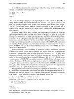
Figure 3.1 shows the concept of Classic Ethernet. It consists of a common coaxial
cable bus to which all stations are connected. Operation is half-duplex. Only one
station can transmit data at a time, and, when transmitting, it cannot receive. Each
station monitors the activity on the bus to determine when to send frames.
3.1.1.1 Carrier Sense Multiple Access with Collision Detection
To provide access to the common channel, Classic Ethernet employed a procedure
known as carrier sense multiple access with collision detection (CSMA/CD). When
activity on the common channel ceases, in case the frame just sent is one of a series,
the station with a frame to send waits for a time equal to the Ethernet interframe
gap. The end of an Ethernet frame is not marked explicitly. Instead, a gap is left
between frames that is equivalent to 96 bit times. The station then waits a further
43
time period that is a random multiple of the slot time. [Slot time is the round-trip
transmission time between a node at one end of the network and a node at the other
end of the network. Usually, a slot time is assumed to be 512 bit times (i.e., 51.2
µsecs for a 10-Mbps LAN).] If there is still no activity, the station may send the
frame. Once any station has begun transmission, other stations should detect the
activity and withhold their own frames. If two, or more, stations begin to transmit at
the same time, a collision will occur. They will detect they are interfering with each
other, and will jam one another for a short time, so that all stations can hear that a
collision has occurred. Then they cease transmitting. The jamming signal is 4-bytes
long (usually 0×AA-AA-AA-AA). More precisely, a collision will occur if two sta-
tions begin transmissions within the time it takes signals to propagate from one to
the other. For this reason, limits are placed on the distances separating terminals. On
ceasing to send, the stations back off for a random number of slot times and try
again. If the network is encountering heavy traffic, a collision may occur (with a dif
-
ferent station) on the second attempt. The station will jam and back off again. After
a number of unsuccessful attempts, the station will abandon the effort to send its
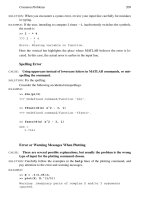
message. Figure 3.2 provides a basic flowchart summary of CSMA/CD. Each termi
-
nal constantly monitors the state of activity on the LAN and follows the decision
sequences on the chart.
3.1.1.2 Ethernet Frame Encapsulation
Internet Protocol (IP) datagrams and Address Resolution Protocol (ARP) messages
sent over a Classic Ethernet network link are encapsulated as shown in Figure 3.3.
Appendix B includes a listing of the fields in a Classic Ethernet frame.
In an Ethernet header the preamble serves to synchronize the receiver with the
frame. The destination address follows. It may be unicast, multicast, or broadcast.
The source address is a unicast address. These 6-byte addresses are assigned to the
source and destination hardware at the time of manufacture. To complete the
header, the EtherType field contains code that identifies the upper layer protocol in
the payload.
44 Local Area Networks
DTE
E/D
EC
DTE DTE DTE
Monitors receive channel for frames addressed to station, for periods
of no activity, and to detect collisions when sending frames
When no signal activity is detected on bus by receive channel, waits
for a known time period then sends frame. Station broadcasts frame
to all connected DTEs. If collision is detected, stops sending, jams for
a short time, and tries again later.
Common bus
Ethernet controller
Encoder/decoder
Transceiver
Figure 3.1 Principle of Classic Ethernet LAN.
An Ethernet trailer consists of a 4-byte frame check sequence (FCS) generated
by the source. Independently, the receiver calculates a FCS. If it agrees with the
source FCS, it is highly likely that the frame has been received without error. If it
does not agree, the receiver discards the frame.
3.1.2 IEEE 802.3 (Ethernet) LAN
The IEEE extended the performance of Classic Ethernet with respect to message
handling. To do this, they added additional fields to the header.
3.1.2.1 LLC and MAC Sublayers
In the IEEE LAN model, layer #2 of the OSI model is divided into the logical link
control (LLC) sublayer and the medium access control (MAC) sublayer. Figure 3.4
compares them with the data link and physical layers of the OSI model, and the net
-
work interface layer of the Internet layer. The functions of these sublayers are:
•
Logical link control (LLC) sublayer: Defines the format and functions of the
protocol data unit (PDU) passed between service access points (SAPs) in the
source and destination stations. SAPs are ports within the sending or receiving
3.1 Ethernet 45
Collision?
Send
No
Abandon attempt
to send frame
Yes
Tried to
send N
times?
No
Monitor input
channel
Jam
Frame sent
Stop sending
Yes
Frame
to send?
No
activity?
No
Yes
No
Yes
Monitor
signal
activity
Wait
interframe
time
Start
Wait
random
time
Still no
activity?
No
Yes
Figure 3.2 Principle of carrier sense multiple access with collision detection.
device that permit PDUs to flow to/from the upper level protocol agent identi-
fied by the EtherType entry. SAPs are associated with specific applications so
that messages created by executing the applications can be identified and cor
-
related. The LLC sublayer is standardized in IEEE 802.2.
•
Medium access control (MAC) sublayer: Defines the format and functions of
headers and trailers that encapsulate the PDUs. The MAC sublayer contains
the hardware addresses of source and destination. The MAC sublayer is stan
-
dardized in IEEE 802.3.
3.1.2.2 IEEE 802.3 Ethernet Frame
An IEEE 802.3 frame is shown in Figure 3.5 and listed in Appendix B. A comparison
of Figures 3.3 and 3.5 shows that the simplicity of the Classic Ethernet header stands
in strong contrast to the header of the IEEE 802.3 Ethernet LAN. The header con
-
sists of three sections.
•
IEEE 802.3 MAC header: The combination of the preamble field and start
delimiter is the same as the 8-byte preamble at the beginning of the Classic Eth
-
ernet frame. In the address fields, the two addresses must be the same length;
they can be 2 or 6 bytes long. The former accommodates private network
addresses generated locally. (Two-byte addresses are hardly ever used.) The
latter accommodates the 6-byte hardware addresses assigned to equipment at
46 Local Area Networks
Preamble
8 bytes
6 bytes
Destination
address
6 bytes
Source
address
2
bytes
4 bytes
FCS
IP datagram
46 to 1500
bytes
Header
Ether-
type
Trailer
Figure 3.3 Classic Ethernet frame.
OSI
Logical link
control sublayer
Medium access
control sublayer
Physical
Data link
Physical
Data link
sublayer
Physical
sublayer
IEEE 802.3
Internet network
interface layer
Logical Link Control Sublayer: defines format and functions of PDUs passed
between SAPs (service access points) in source and destination
Medium Access Control Sublayer: defines format and functions of Headers
a
n
d
Tr
a
il
e
r
st
h
at a
r
e added to
PD
Us
Figure 3.4 Comparison of layers in OSI, IEEE 802.3, and Internet models.
the time of manufacture. The length field indicates how many bytes are con
-
tained in the remaining two headers and the payload so that the receiver can
detect the frame check sequence. The length will be less than 1,500 bytes (i.e.,
≤0×05-DC). A value of ≤ 0×05-DC identifies the frame as an IEEE 802.3 Eth-
ernet frame. A value ≥ 0×05-DC identifies the frame as a Classic Ethernet
frame in which this field is EtherType. The lowest EtherType value is
0×06-00.
•
IEEE 802.2 LLC header: The destination and source SAP (DSAP and SSAP)
fields identify the points to which the payload is to be delivered in order to
reach the proper upper-layer protocol. DSAP and SSAP act as upper-layer
protocol identifiers. For IP, the value of both source and destination SAPs is
0×06. When used in conjunction with a SNAP header, DSAP and SSAP are set
to 0×AA. This passes responsibility for identifying the upper-layer protocol to
the SNAP header. The control field is 1 or 2 bytes long, depending on whether
the LLC-encapsulated data is part of a connectionless communication (identi
-
fied as Type 1) or a connection-oriented communication (identified as Type
2). IP datagrams and ARP messages are sent as Type 1.
•
IEEE 802.3 SNAP header: The organization code field identifies the organiza
-
tion that maintains the meaning of the EtherType field that follows. For IP
datagrams and ARP messages, the organization code is set to 0×00-00-00.
The EtherType field is set to 0×08-00 for IP datagrams, and to 0×08-06 for
ARP messages.
3.1.2.3 Subnetwork Access Protocol
IEEE 802.3 Subnetwork Access Protocol (SNAP) was created to permit protocols
designed to operate with a Classic Ethernet header to be used in IEEE 802.3 applica
-
tions. Messages sent over an IEEE 802.3 LAN use SNAP headers to identify the
upper level protocols in use. The header contains a 3-byte organization code that
identifies the organization responsible for defining the EtherType field that follows.
For an IP datagram, or an ARP message, the organization code is set to 0×00-00-00.
A 2-byte EtherType field that identifies the upper-layer protocol in use in the payload
3.1 Ethernet 47
7
6
Destination
address
6
Source
address
2
1
4
FCS
ET
2
1
1
1
Org
code
3
IP
datagram
38 to 1492
Bytes
DSAP = Destination Service Access Point
SSAP = Source Service Access Point
ET = Ether Type
FCS = Frame Check Se
q
uence
IEEE 802.3
trailer
Preamble
802.3 MAC header
Length
Start
DSAP
SSAP
Control
802.2 LLC
802.3 SNAP
IEEE 802.3 header
Figure 3.5 IEEE 802.3 Ethernet frame.
follows the Organization code. For an IP datagram, it is set to 0×08-00, and for an
ARP message, it is set to 0×08-06. To keep the length ≤ 1,500 bytes, and accommo
-
date the length of the extra headers (3 bytes for LLC and 5 bytes for SNAP), the pay
-
load is reduced by 8-bytes.
3.1.2.4 Additional Services
The additional information contained in the header permits three classes of services
to be provided by IEEE 802.3 Ethernet. They are:
•
Connection-oriented service: A logical connection is set up between originat
-
ing and terminating stations. Acknowledgments, error and flow controls, and
other features are employed to ensure reliable data transfer. For this reason,
the IEEE 802.3 header contains internal logical connection points (SAPs) for
both source and destination. They are used to ensure the source’s frame(s) and
the receiver’s response(s) are delivered to the proper upper-layer protocols.
•
Acknowledged connectionless service: The receiver acknowledges messages,
but a logical connection is not established. This technique is used when the
overhead (error control, flow control) associated with connection-oriented
service would make the operation too slow, yet it is important to know that
the message was received.
•
Unacknowledged connectionless service: The receiver does not acknowledge
messages. Error control and flow control are not employed. The service is used
in applications where the occasional loss or corruption of a PDU can be
corrected by procedures invoked by the upper layer communicating software
entities.
In the source address and destination address fields of Classic Ethernet and IEEE
802.3 Ethernet frames, special bits are defined:
•
The Individual/Group (I/G) bit (bit 1 in byte 0 of destination address) indicates
whether the address is unicast (0) or multicast (1). For a broadcast address
(which is a special case of multicast), the I/G bit is set to 1.
•
The universal (global)/local (U/I) bit (bit 2 in byte 0 of destination and source
addresses) indicates whether the address is globally unique (0) or locally
administered (1). Globally unique addresses are controlled by IEEE and
assigned to manufacturers to imprint during the manufacturing process.
•
The routing information indicator bit (bit 1 in byte 0 of the source address)
indicates whether Token Ring source routing information is present (1).
Source routing allows a Token Ring sending node to discover and specify a
route to the destination in a Token Ring segment.
3.1.3 New Configurations
Obviously, the throughput an Ethernet station achieves depends on the number
of active stations and the speed of the bus. As the number of users increases, their
average speed falls off, and the throughput of individual stations may become unac
-
ceptable. In addition, as the number of users grows, it is likely that the number of
48 Local Area Networks
rearrangements that must be made to accommodate them increases. With a shared
cable medium, this means constant splicing and rerouting as the cable is moved to
include new, and/or eliminate old, stations.
In the early 1990s, technical improvements made it possible to connect the sta
-
tions in a star configuration with twisted pairs. Pairs leading to a hub in a wiring
closet replaced the shared cable. Now, changing connections on a wiring strip could
add or delete stations. Later, a switch replaced the hub. The operation moved to 100
Mbps and 1,000 Mbps, and some connections use optical fibers.
Fast Ethernet products (i.e., those that operate at 100 and 1,000 Mbps) employ
block coding. At 100 Mbps, the code is designated 4B/5B. Five bits substitute 4 bits
in the data frame. Code patterns are selected so that the number of 1s and the
number of 0s differ by no more than one. The signaling rate for 100 Mbps products
is 125 Mbps. At 1,000 Mbps, the code is 8B/10B. Ten bits substitute 8 bits in the
data frame. Code patterns are selected so that the number of 1s and the number of
0s differ by no more than two. The signaling rate for 1,000 Mbps products is 1,250
Mbps. More information can be found in Appendix A.
3.1.3.1 Ethernet Hub
The implementation of a common hub to which each station is attached by separate
twisted pair cables, drastically modified the shared bearer approach to Ethernet.
The hub is a combiner and a repeater. It may perform amplification, retiming, and
reshaping in order to prepare the signal for retransmission. It provides a separate
port for each attached station and creates the equivalent of a shared environment. It
uses the same CSMA/CD algorithm to allocate the channel capacity to individ-
ual stations. Single repeaters provide from 8 to 24 ports. The combination of
hub/repeater and attached stations is referred to as a collision domain. The repeater
performs the following functions:
•
Receives data from a transmitting station, restores the amplitude, timing, and
shape of the received signal, and retransmits it on all ports except the port on
which it was received.
•
Detects simultaneous activity on two or more input ports and broadcasts a
collision alert (jamming signal).
•
May detect and disconnect stations that have failed in a continuous transmit
mode (jabbering mode).
Figure 3.6 shows the principle of a repeater hub. Two pairs are used to connect
each port to a single station. All stations must operate at the same data speed.
3.1.3.2 Switched Ethernet
The hub configuration suggests that the network might be modified to substitute a
nonblocking, high-speed switch for the connection plane of the repeater hub. Then
the two stations involved in a message transfer can be connected directly over a
high-speed channel. Collisions are eliminated. CSMA/CD is no longer needed. Sta
-
tions do not have to wait for the bus to be quiet, and they can operate at the full bit
3.1 Ethernet 49
rate of the switching fabric. Figure 3.7 shows the principle of a switched hub. Two
methods of operation are employed:
•
Store-and-forward: The entire frame is received and stored in the input buffer
before being forwarded over a switch path to the buffer serving the port con-
nected to the destination. In the process of storing the frame, the buffer logic
may check for errors and perform other frame management functions.
•
Cut-through: As soon as the destination address is received in the input buffer,
the number of the output port is obtained from a table of ports and addresses.
If a path through the switch to the designated port is available, the frame is fed
to it. Should the port be busy with other traffic, the frame is stored in the input
buffer to wait for the interfering traffic to clear.
50 Local Area Networks
R
D
R
D
D
R
Port 1
DTE
DTE
DTE
Buffers
Buffers
Buffers
Port 2
Port 3
R Repeater; D Driver
Connections
Figure 3.6 Principle of repeatered Ethernet hub.
R Repeater; D Driver
R
D
R
D
D
R
Port 1
DTE
DTE
DTE
Buffers
Buffers
Buffers
Port 2
Port 3
R
D
DTE
Buffers
Port 4
Switch fabric
Figure 3.7 Principle of switched Ethernet hub.
For slower-speed operation (10 Mbps), the switch can be a crossbar. Crossbar
switches have a plurality of horizontal and vertical paths and a means for intercon
-
necting any one of the vertical paths with any of the horizontal paths. For higher-
speed operation (100 Mbps or 1 Gbps) the switch can be a self-directing, high-speed
switching fabric such as that used in asynchronous transfer mode (ATM) switches.
The switches can be blocking (i.e., setting up an arbitrary switching path may not be
possible because of an existing switching path) or nonblocking (i.e., an existing
switching path cannot prevent the setting up of another switching path). Most
switched Ethernets employ a nonblocking architecture.
Because the switch makes a direct connection from sender to receiver, it is possi
-
ble to host 10 Mbps, 100 Mbps, and 1,000 Mbps stations on the same LAN. Of
course, connections can only be made between stations operating at the same speed.
This behavior is in direct contrast to a shared repeater hub on which all stations
must operate at the same speed.
Switched hubs permit the linking of several shared LANs into a common data
space without expanding their individual collision domains. Figure 3.8 shows the
principle. Three repeater hub Ethernets are connected by a switched hub. Within
each LAN, the stations employ CSMA/CD and are governed by the carrier sense,
collision detect, backoff, and try-again rules. Between the LANs, frames are passed
across the switch without hindrance. However, the switch ports must obey the
CSMA/CD rules when moving frames back into a collision domain.
3.1 Ethernet 51
Collision domain 3
Repeater HUB
Repeater HUB
Switched
HUB
Collision domain 1
Collision domain 2
Repeater HUB
Figure 3.8 Use of switched hub to link Ethernets and separate collision domains.
3.1.3.3 Ethernet Designations
Different styles of Ethernet are identified as follows:
•
Bus connected: In the designator, 10 = 10 Mbps speed; BASE = baseband sig
-
nal; 5 = 500m; 2 = approximately 200m.
•
10BASE5. 0.40-inch diameter coaxial cable bearer limited to segments of
500m and 100 nodes per segment when operating at 10 Mbps with Man
-
chester signaling.
•
10BASE2. 0.25-inch diameter coaxial cable bearer limited to segments of
185m and 30 nodes per segment when operating at 10 Mbps with Man
-
chester signaling.
•
Hub connected: In the designator, 10 = 10 Mbps speed; 100 = 100 Mbps
speed; 1,000 = 1 Gbps speed; BASE = baseband signal; T = unshielded twisted
pair; F = optical fiber. Some examples are:
•
10BASE-T. Operates at 10 Mbps. Employs two unshielded twisted pairs
(UTPs) connected in a star. Each pair of UTPs supports a single station that
is no more than 100m from the hub. Capable of full-duplex operation.
•
10BASE-F. Operates at 10 Mbps. Employs two multimode optical fibers to
connect hubs separated by up to 2 kms. Fibers are run between the hubs.
Each hub is connected to its community of users by UTPs. Capable of full-
duplex operation.
•
100BASE-TX. Operates at 100 Mbps. Employs two Category 5 UTPs, or
shielded twisted pairs (STPs) and two multimode optical fibers to intercon-
nect hubs. Uses 4B/5B coding. Stations are limited to less than 100m from a
hub. Capable of full-duplex operation.
•
100BASE-FX. Operates at 100 Mbps. Employs two multimode optical fi-
bers to connect stations to hub. Uses 4B/5B coding. Fibers are limited to 2
kms. Capable of full-duplex operation.
•
1000BASE-CX. Operates at 1,000 Mbps. Employs two balanced copper
cables. Uses 8B/10B coding. Stations are limited to 25m from hub. Capable
of full-duplex operation.
•
1000BASE-TX. Operates at 1,000 Mbps. Employs four pairs of Category 5
UTP and multimode optical fibers to interconnect hubs. Uses 8B/10B cod
-
ing. Stations are limited to 100m from hub. Capable of full-duplex opera
-
tion.
3.2 IEEE 802.5 Token-Ring LAN
In a Token Ring LAN each station is connected to two others to form a single loop
that connects all stations. Each station:
•
Receives the data stream from the station preceding it on the ring;
•
Regenerates it;
•
May add to or change it;
52 Local Area Networks
•
Sends the data stream to the next station on the physical ring.
The cabling system uses twisted-pairs with Manchester signaling. Data speeds
of 4 Mbps, 16 Mbps, and 100 Mbps are in use. A multistation access unit (MAU)
provides the ability to connect stations by UTP wiring to a central device in which
the token ring is implemented. Figure 3.9 shows the concept. Furthermore, MAUs
can be connected together in a ring so as to connect communities of stations. If the
ring consists of dual cables (or fibers), it can be made self-healing by arranging for
one of the cables/fibers to reverse itself to provide loopback in the event of a failure.
3.2.1 What Is a Token?
A token is an access control byte with start and end delimiters. The byte contains:
•
Three priority bits (PPP), which identify the level of priority a station must
have to seize the token.
3.2 IEEE 802.5 Token-Ring LAN 53
Implementation
Multistation access
unit (MAU)
Token
circulation
DTE
DTE
DTE
DTE
DTE
DTE
DTE
DTE
IF DTE has frame to send, AND has sufficient priority, AND Token is
empty, DTE seizes Token and sends
Receives frames from preceding DTE
Sends frames to next DTE
Concept
R
R
R
R
R
R
R
R
R = RX/Repeater/TX
Figure 3.9 Principle of Token Ring LAN.
•
A token bit (T), which gives the token status. If it is 0, the token has not been
taken and a station that has sufficient priority may seize it. If it is 1, the token
has been seized by another station and the frame is in use.
•
A monitor bit (M), which is used to detect unclaimed frames.
•
Three reservation bits (RRR), which provide a mechanism for lower priority
devices to request the opportunity to transmit.
Figure 3.10 shows the sequence of activities associated with receiving a frame,
determining whether the token is available, and influencing the availability of the
token at some future time.
3.2.2 Token Ring Frame
Figure 3.11 shows a token and the fields in a frame containing an IP datagram. The
frame consists of an IEEE 802.5 header, an IEEE 802.2 LLC header, an IEEE 802.3
SNAP header, the payload (IP datagram), and an IEEE 802.5 trailer. Appendix B
includes a listing of the fields of an IEEE 802.5 Token Ring frame. They are summa
-
rized here:
•
IEEE 802.5 header: The start delimiter field alerts the receiver to the incoming
frame and provides a synchronizing signal. It contains two nondata symbols
54 Local Area Networks
Copy frame
return frame
Destroy frame
re-issue token
Sent by
station?
Yes
No
Station
address?
Yes
No
Upgrade
RRR
Have
Frame to
Send?
My
Priority
RRR?≥
Yes
Yes
No
No
Send
token on
Is
T=0?
My
priority
≥ PPP?
Have
frame to
send?
Seize token
send frame
No
Yes Yes
Yes
No
No
Send frame on
Receive
frame
Figure 3.10 Major procedures in Token Ring LAN.
(called J and K) that are violations of the signaling scheme. The J symbol is an
encoding violation of a 1 and the K symbol is an encoding violation of a 0. The
access control field is the key to token management and has been discussed
above. The frame control field contains 2 bits reserved for future use and 6
active bits. They identify the frame that follows as a Token Ring MAC man
-
agement frame or a Token Ring data frame. The address fields contain the
unicast hardware addresses of the destination and source or multicast or
broadcast addresses.
•
IEEE 802.2 LLC header: For IP datagrams and ARP messages, the SNAP
header preempts the LLC header. Accordingly, DSAP and SSAP are set to
0×AA, and the control field is set to 0×03. For other upper-layer protocols,
the SNAP header may not be used. In this case, values that identify the points
of origination and delivery of data to upper-layer protocols are present.
•
IEEE 802.3 SNAP header: The organization code is set to 0×00-00-00 for IP
datagrams and ARP messages. The EtherType code is set to 0×08-00 for IP
datagrams and 0×08-06 for ARP messages.
•
IEEE 802.5 trailer: The FCS is calculated over the data stream between the
access control byte and the end of the payload. This allows the access control
and frame status fields to be changed as needed to reflect operations without
recalculating the FCS. The FCS is checked at each node. The end delimiter
3.2 IEEE 802.5 Token-Ring LAN 55
P
Access control
PPTM
RRR
If station can seize empty token, sets
token bit and adds frame information
Start delimiter
Access delimiter
End delimiter
Empty
token
0xJK
0xJK
Frame control
Frame status
Destination
address
Source address
Destination SAP
Source SAP
Control
Organization
code
EtherType
IP datagram
End delimiter
FCS
111
1111 11
66
P Priority bit
T Token bit
M Monitor bit
R Reservation bit
3
2
4
Payload
≤
≤
4464 bytes (4 Mbits/s)
17,914 bytes (16 Mbits/s)
Bytes
Bytes
IEEE 802.5 header
LLC
header
SNAP
header
IEEE 802.5
trailer
Figure 3.11 Token Ring frame.
contains J and K nondata symbols. In addition, it contains an intermediate
frame indicator bit that identifies whether this frame is the last in a sequence
(0), or there are more frames to follow (1). The end delimiter byte also con
-
tains an error detected indicator bit. Should the FCS fail, the node performing
the check sets this bit and the destination node does not copy the frame. The
frame status field contains duplicate address recognized indicator and frame
copied indicator bits. They are used by the destination to inform the sender
that the node recognized its address and successfully copied the frame. The bits
are duplicated because the field is not included in the FCS.
3.3 Fiber Distributed Data Interface
Fiber distributed data interface (FDDI) employs a ring topology and uses a shared
multimode fiber medium. Figure 3.12 shows the concept of FDDI. It can include a
dual-fiber ring so that the system can recover from a single catastrophic fault. FDDI
uses block coding (4B/5B). The signaling rate is 125 Mbps. A version of FDDI that
works over wire pairs is available. It is limited to a maximum length of 100m.
FDDI provides a relatively expensive solution to obtaining a local or metropolitan
area network operating at 100 Mbps. It is being displaced by 100BaseTX and
1000BaseTX Ethernets.
Providing connectionless delivery using 48-bit addressing and token passing
similar to IEEE 802.5 Token Ring, FDDI can be bridged to Ethernet. Standard pro-
tocol stacks communicate over FDDI in the same way they communicate over the
Ethernet. Figure 3.13 shows an FDDI frame that encapsulates an IP datagram.
Intentionally, it is very similar to frames for IEEE 802.3 and IEEE 802.5. Like them,
when transporting IP datagrams and ARP messages, FDDI uses a SNAP header to
identify the upper-layer protocol carried in the frame. The contents of the fields of
an FDDI frame are listed in Appendix B.
56 Local Area Networks
Router
ATM
switch
FDDI ring
High-speed
customers
FDDI
customers
100 Mbits/s dual optical
fiber ring
FDDI
concen-
trator
Router
Ethernet
customers
FDDI
concen-
trator
FDDI
customers
Figure 3.12 Principle of FDDI.
3.4 Bit Ordering
Ethernet uses little endian bit order and Token Ring/FDDI use big endian order. To
make MAC address transmissions consistent between the two styles of LANs,
Token Ring/FDDI systems store multibyte addresses in bit-reversed order compared
to Ethernet. Figure 3.14 gives an example of the same 6-byte address stored in the
Ethernet and the Token Ring/FDDI:
•
In the Ethernet, the least significant bit in each byte occupies the rightmost bit
position. Data streams are formed up beginning with the LSB. Bytes are taken
in order from left to right.
•
In the Token Ring/FDDI, the least significant address bit in each byte is stored
in the rightmost bit position. Addresses are read out to data streams beginning
with the rightmost bit in each byte. Bytes are taken in order from left to right.
3.4 Bit Ordering 57
0xAC-E1 23-45 67-89
1010 1100 1110 0001 0010 0011 0100 0101 0110 0111 1000 1001
Address stored by ethernet
canonical format
0011 0101 1000 0111 1100 0100 1010 0010 1110 0110 1001 0001
Unicast/multicast bit
Local/global bit
Address stored by Token ring or FDDI
reverse bit order
0011 0101 1000 0111 1100 0100 1010 0010 1110 0110 1001 0001
6-byte MAC address 0x35-87 C4-A2 E6-91
as it appears in data stream
0x35-87 C4-A2 E6-91
Figure 3.14 Difference in Ethernet and Token Ring/FDDI storage conventions.
2 bytes
Preamble
6 bytes
6 bytes
Source
address
1
byte
1
byte
Destination
address
00
0xAA-AA
00
FDDI MAC header
1
byte
1
byte
1
byte
Header
IEEE 802.2LLC
4 bytes
Frame check
sequence
1
byte
1
byte
End
Ether-
Type
2 bytes
Organization
code
3 bytes
IP datagram
4352 bytes≤
SNAP header
Payload FDDI MAC trailer
DSAP Destination service access point
SSAP Source SAP
Start
Frame
control
Frame
status
JK
JK
01xxxxx
x
DSAP
SSAP
Control
0xAA
0xAA
0x03
0x00-00-00
0x08-00
or
0x08-06
Figure 3.13 FDDI frame.
In the data stream, a MAC address might read 0×35-87-C4-A2-E6-91. When
stored in an Ethernet LAN it will be 0×AC-E1-23-45-67-89. When stored in Token
Ring or FDDI LANs it will be 0×35-87-C4-A2-E6-91. (The 0×AC-E1-23-45-67-89
and 0×35-87-C4-A2-E6-91 are different representations of the same address.)
58 Local Area Networks
CHAPTER 4
Wide Area Networks
Wide area networks (WANs) consist of long-distance links joined together at various
points by nodes that perform switching or routing functions. The nodes move frames
from one link to another to guide them between the sending local network and the
receiving local network. Because long-distance transport is expensive, all links will
carry several channels multiplexed together. The links employ a variety of transmis
-
sion techniques. Optical fibers and microwave radios probably carry the bulk of
WAN traffic. They are supported by twisted pairs and other telephone cables and, in
some cases, by wireless networks and communication satellite circuits.
Operations in the physical sublayer are synchronous or asynchronous:
•
Synchronous operation: Actions occur at specific times in synchrony with
other units in the network. A hierarchy of clocks synchronizes the entire net-
work. They provide timing to all major facilities. The receiver uses one of
these clocks to identify the boundaries between codes in the frames it receives.
Synchronous operation is used in digital telephone networks. The frames
require rudimentary headers and/or trailers. Examples are T-carrier networks,
ISDNs, and SONETs. In addition, synchronous facilities are used to carry
data traffic.
•
Asynchronous operation: Nodes operate with similar internal clocks, but
their actions are not synchronized or coordinated. To identify the bounda-
ries between codes, the receiver recovers timing from bit transitions in the
flag, or other synchronizing characters in the bit stream. Primarily, asyn
-
chronous operation is used in data networks. Examples are modem-
mediated data connections over telephone lines, Ethernet LANs, and X.25
packet networks.
Before transfer to the physical medium, IP datagrams are encapsulated by net
-
work interface layer headers and trailers. They perform the same services as their
LAN counterparts (i.e., delimitation, protocol identification, addressing, and bit-
level integrity checking). WAN connections are divided into:
•
Point-to-point links: They form a network segment with two terminal nodes.
These links include telephone lines, ISDN circuits, digital subscriber lines, and
T-carrier links.
•
Nonbroadcast multiple access (NBMA) links: They connect more than two
nodes but do not provide multicast or broadcast services. The physical link
supports multiple virtual circuits that may connect to different nodes and dif
-
59
ferent service access points (SAPs). NBMA links include those that operate
with X.25, frame relay, and asynchronous transfer mode (ATM). In an IP
environment, inverse ARP (InvARP) is used to discover the IP addresses of the
nodes on the other ends of the virtual circuits.
4.1 Point-to-Point Links
Normally, private data circuits are enabled (turned up) at system generation. Absent
users’ traffic, they exchange short frames continuously. These frames serve to syn
-
chronize receivers to data streams and confirm that stations are ready to send or
receive traffic. Frames are moved over point-to-point links by simple protocols such
as PPP and SLIP. PPP employs the basic data link protocol, HDLC.
4.1.1 High-Level Data Link Control Protocol
High-Level Data Link Control Protocol (HDLC) was first designed to work with
packet networks. Standardized by ISO, HDLC makes use of a special character, the
flag character (01111110 or 0×7E), to mark the beginning and ending of the frame.
Between these markers, the header and the trailer fields are of predetermined
lengths. The data that lie between the header and trailer are the payload. Over time,
several variations of HDLC have appeared:
•
LAP-B: Link Access Protocol—Balanced, first applied to the user-network
interface (UNI) of X.25 packet-switched networks. Works in asynchronous
balanced mode (ABM). The stations have equal status and each station may
initialize, supervise, recover from errors, and send frames at any time. LAP-B
served as the model for LAP-D and LAP-F.
•
LAP-D: Link Access Protocol—Channel D, first applied to the data channel
(D-channel) in ISDN. Works in ABM.
•
LAP-F: Link Access Procedure—Frame Mode, first applied to frame mode
services over the ISDN UNI on B-, D-, or H-channels.
•
PPP: Point-to-Point Protocol, provides full-duplex data link services between
peers (discussed later in this chapter).
Since LAP-D is included in PPP, I will describe its features in more detail.
Figure 4.1 shows the format of a LAP-D frame and details the structure of the
address and control fields.
4.1.1.1 LAP-D Address Field
The 2-byte address field marks the beginning of the first byte with 0 (bit 1) and the
beginning of the second byte with 1 (bit 9). In byte 1, bit 2 identifies the frame as a
command or response. A command frame requires an answer from the receiver. A
response frame is the reply. The remaining bits of the 2-byte address field are divided
between the terminal endpoint identifier (TEI, bits 3 through 8) and the service
access point identifier (SAPI, bits 10 through 16):
60 Wide Area Networks
•
Terminal endpoint identifier (TEI): Each physical node is assigned an address
identifier. Assignment may be manual or automatic. The values are:
•
0 through 63, manual assignment;
•
64 through 126, automatic assignment;
•
127 for temporary use during automatic TEI assignment.
•
Service access point identifier (SAPI): Each node may support several Internet
layer protocols. SAPI values are assigned that identify the buffer/queue (SAP,
service access point) serving the specific protocol in the destination machine.
Called a data link connection identifier (DLCI), the combination of TEI and
SAPI identifies a unique logical connection to an Internet layer protocol in a specific
receiving device. The sending terminal may support several DLCIs simultaneously.
They can be logical connections to different Internet layer protocols (control, net
-
work, or management protocols, for instance) in the same terminal or connections
to different terminals (and Internet layer protocols). A given SAP is connected by a
single DLCI to the sending/receiving machine.
4.1.1.2 LAP-D Control Field
LAP-D employs three types of frames. They are distinguished by the format of the
control field. It occupies 1 or 2 bytes. The three types of frames are:
4.1 Point-to-Point Links 61
Address Control
Payload
FCS
Bytes
Flag Flag
12
1or2
Variable
21
Frame format
C/R SAPI TEI
Address field
67
Bits
0
0
N(S)
P/F
N(R)
Control field—Information frame
77
Bits
Control field—Supervisory frame
67
Bits
P/F
M
Control field—Unnumbered frame
23
Bits
S
P/F
N(R)
M
C/R Command/Response
SAPI Service access point identifier
TEI Terminal endpoint identifier
N(S) Transmitter send sequence number
N(R) Transmitter receive sequence number
S Supervisory function codes
M Modifier function codes
P
/
F Poll
/
Final bit
1
1
11
0
Figure 4.1 HDLC Link Access Protocol—Channel D.
Information (I) frame. In the 2-byte control field:
•
To identify an I-frame, the first bit of the first byte of the control field is set
to 0.
•
Bits 2 through 8 contain the number [N(S), 0 through 127] of this frame in the
sending sequence.
•
The first bit (bit 9) of the second byte is the P/F bit. In command frames, it is
known as the poll (P) bit. When set to 1, it identifies this frame as requiring a
response from the receiver. When set to 0, a response is not required. In
response frames, the P/F bit is known as the final (F) bit. When set to 0, it iden
-
tifies this frame as one of a continuing sequence. When set to 1, it is the final
frame in the sequence.
•
Bits 10 through 16 contain the number N(R) of the frame the sender expects to
receive (0 through 127). It serves to acknowledge all frames up to N(R).
The information field must be an integral number of bytes. When user’s data
(payload) is sent, an information frame executes acknowledged operation. The N(S)
and N(R) values provide the basis for error control (go-back-n) and flow control. In
addition, I-frames carry control and management information.
Supervisory (S) frame. In the 2-byte control field:
•
To identify an S-frame, the first 2 bits of the first byte of the control field are
set to 01.
•
Bits 3 through 8 contain codes for error and flow control: Receiver Ready
(RR, 000000), Receiver Not Ready (RNR, 100000), and Reject (REJ,
010000). A supervisory frame is used when the receiver has no data ready to
send in reply. RR signifies a positive acknowledgement and indicates ready to
receive the next I-frame [N(R)]. RNR signifies a positive acknowledgment and
indicates the receiver is not ready to receive next I-frame [N(R)]. REJ signifies
a negative acknowledgment and indicates the sender must resend from N(R)].
•
Bit 9 is the P/F bit.
•
Bits 10 through 16 contain the number [N(R), 0 through 127] of the frame the
sender expects to receive. It serves to acknowledge all frames up to N(R).
Unnumbered (U) frame. This frame provides unacknowledged service without
flow control. Error detection is implemented, but not error correction. Upon
detecting an error, the frame is discarded. In the 1-byte control field:
•
To identify a U-frame, the first 2 bits of the first byte of the control field are set
to 11.
•
Bits 3 and 4, and bits 6 through 8 are codes that initiate communication, con
-
figure stations, test capabilities, and so forth.
•
Bit 5 is the P/F bit.
62 Wide Area Networks
4.1.2 PPP and SLIP
Point-to-Point Protocol (PPP) and Serial Line Internet Protocol (SLIP) are used to
transport IP datagrams over point-to-point connections.
4.1.2.1 PPP
PPP encapsulates an IP datagram with an HDLC header and trailer. The frame is
listed in Appendix B. Because it is a point-to-point connection, the three fields of the
HDLC header—address, control, and protocol—can be omitted, or set as 0×FF
(address), 0×30 (control), meaning an unnumbered information (UI) frame with
poll/final bit set to 0, and 0×00–21 (protocol). The default value of the maximum
size PPP frame [the maximum receive unit (MRU)] is 1,500 bytes (to be compatible
with Ethernet). Other values (higher or lower) can be negotiated. PPP is used with
SONET and SDH (see Section 7.4) and other transport systems.
4.1.2.2 Transparent Operation
On asynchronous links (such as modem mediated analog telephone lines), so that a
flag character or an escape character within the IP datagram payload shall not inter-
rupt transmission, PPP employs character stuffing to change the meaning of the
offending character:
•
In the IP datagram, a character that mimics the flag character (0×7E) is
replaced by the sequence 0×7D–5E. 0×7D is the ESC character. At the receiv-
ing node, 0×7D–5E is replaced by 0×7E.
•
An escape character within the IP datagram is replaced by 0×7D–5D. At the
receiving node, 0×7D–5D is replaced by 0×7D.
•
If the IP datagram contains the sequence 0×7D–5E, it is replaced by
0×7D–5D–5E.
In addition, a combination of character stuffing and bit stuffing is used to pre
-
vent characters in an IP datagram with values less than decimal 32 (i.e., less than
0×20) being interpreted as control characters. The ESC character is placed ahead of
the character and the 6th bit is set to 1. [For instance, character 00010001 (0×11)
becomes 0×7D–31 (i.e., 01111101 – 00110001)].
On synchronous links (such as T-carrier, ISDN, and SONET), bit stuffing is
used between the framing flags to break up strings of 1s into segments of five 1s.
Without regard to byte boundaries, 0 is stuffed after a sequence of five 1s. In this
way, only the beginning and ending flags contain six consecutive 1s. As an example,
consider the following data stream which has been divided into bytes for easier
reading:
⇐01111110/01011111/11111101/11111011/01111110
The first 8 bits and the final 8 bits are underlined—they are the beginning and
ending flags (07E, 01111110). In between, there is a section of the data stream (also
underlined) that mimics the flag and extends over 2 bytes. Before transmission,
4.1 Point-to-Point Links 63