A Professional’s Guide to Data Communication in a TCP/IP World phần 5 ppt
Bạn đang xem bản rút gọn của tài liệu. Xem và tải ngay bản đầy đủ của tài liệu tại đây (411.72 KB, 27 trang )
point unicast services. Packet-switched WAN links such as X.25, frame relay, and
ATM are examples of NBMA links. The forwarding network address for the route
in the routing table is mapped to the virtual circuit identifier using a table main
-
tained by the sending node. Inverse ARP is used to discover the network addresses
of nodes on the other ends of the virtual circuits.
5.3 Routing 93
Find MAC Address of Destination
Host (Cache, ARP)
Verify FCS
Discard
Is MAC
address of
this router?
Yes
Filter
Yes
Verify header
checksum
Yes
Incoming
IP frame
Queue
Deliver to
destination host
Network
Mask
No
No
Discard
No
Is
network
address of
this
network?
Yes
No
Calculate
new FCS
Queue
Outgoing
IP frame
Find MAC Address of next router
(Cache, ARP)
Yes
Is
fragmentation
required?
No
Fragment
datagram
build headers
Decrement TTL
Calculate New
Checksum
Routing
table
Send ICMP
destination
unreachable
message
Routing
protocols
Advertising
Is
route in
routing
table?
Yes
No
Is
default
route
configured?
Yes
No
Look up
table
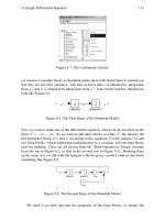
Figure 5.9 Router functions.
5.3.4 Router
Figure 5.9 is a functional diagram of a router. A database of routes is stored and
maintained by all routers. Called a routing table, it contains information concerning
routes between the node owning the table and the potential destination nodes. At a
minimum it includes the destination ID, intermediate interface ID(s) and forwarding
address(es), and information to distinguish the best route to use when multiple
routes are possible. It is significantly more complex than the table maintained by
bridging devices. However, its extent is limited to the immediately reachable nodes
that surround it, so that it is significantly smaller. Searching a routing table is a rela
-
tively simple task. For each route, a typical routing table will include the following
fields:
•
Destination address: The IP address of the node to which the source directs the
packet to be delivered. For direct deliveries, the destination IP address carries
the same network ID as the router. For indirect deliveries, the destination
address does not carry the same network ID as the router, and the datagram is
sent to the forwarding address contained in the table entry.
•
Network mask: A bit mask is used to determine the network ID of the destina-
tion IP address. An IP datagram with a destination IP address that contains the
specific network ID for this route will be forwarded over it.
•
Forwarding IP address: For indirect deliveries, the IP address of a directly
reachable router to which the IP datagram is forwarded for eventual delivery
to the destination IP address. The IP address to which the IP datagram is to be
forwarded on its next hop.
While the routing table contains information on all routes within the router’s
purview, the router maintains a separate look-up table in which all recently used
routes are recorded. If they are not used again within a specified time, they are
purged. Because it does not have to search the larger routing table for directions, the
router can provide rapid service if the routes are called for again before time runs
out. Priority routes can be stored permanently in the look-up table.
5.3.5 Static Routing
Static routing employs manually configured routes. Because of the work involved,
static routing is limited to relatively small networks. Static routing does not scale
well. Often, static routes are used to connect to an ISP router. To make the destina
-
tion unambiguous, a network mask or masks accompanies each route. By definition,
a static router cannot adjust its routing table. That can only be done by manual
intervention. Therefore, a static router is unable to react to the state of contiguous
routers, and neighboring routers cannot update the static router’s table.
5.3.6 Dynamic Routing
Dynamic routers employ routing protocols to dynamically update their routing
tables. When a route becomes unreachable, it is removed from the routing table.
When a router becomes unreachable, alternate routes are worked out and shared
between routers. In a dynamic routing environment, routers are in regular touch
94 Connecting Networks Together
with each other concerning the state and capabilities of the network. Two common
routing protocols used in autonomous networks are Routing Information Protocol
(RIP) and Open Shortest Path First (OSPF).
5.3.6.1 Routing Information Protocol (RIP)
RIP is a simple routing protocol with a periodic route-advertising routine that can
be used in small- to medium-size networks. RIP is described as a distance vector
routing protocol. The distance is the number of hops between the router and a spe
-
cific network ID. RIP recognizes a maximum distance of 15 hops. Destinations with
16 or more hops are described as unreachable.
When an RIP router is initialized, it announces the routes in its table to all inter
-
faces. In RIPv2, to support classless addressing, the announcement includes a net
-
work ID and a network mask. The router continues with an RIP general request to
all interfaces. All routers on the same network segment as the router sending the
request respond with the contents of their routing tables. With these, the requesting
router builds its initial routing table. Learned routes persist for 3 minutes (default
value) before being removed by RIP from the routing table. After initialization, the
RIP router announces the routes in its routing table every 30 seconds (default value).
5.3.6.2 Open Shortest Path First (OSPF)
OSPF is described as a link state routing protocol and a classless routing protocol.
Routing information is disseminated as link state advertisements (LSAs) that con-
tain the IDs of connected networks, network masks, and the cost. The cost of each
router interface is a dimensionless number assigned by the network administrator. It
can include delay, bandwidth, and monetary cost.
The LSA of each OSPF router is distributed throughout the network through
logical relationships between neighboring routers known as adjacencies. When all
current LSAs have been disseminated, the network is described as converged. Based
on the link state database, OSPF calculates the lowest-cost path for each route. They
become OSPF routes in the IP routing table.
To control the size of the link state database, OSPF allows contiguous networks
to be grouped into areas. A router at the border of an OSPF area can be designated
an area border router. Reached by a single route from outside routers, it aggregates
routing information for the area. The formation of areas and the use of route aggre
-
gation permit OSPF networks to scale gracefully to large IP networks.
5.3.7 Border Gateway Routing
The foregoing discussion of routing has assumed it takes place in contiguous net
-
works administered by a single entity (such as an enterprise or an ISP). In these
autonomous networks, the operator stipulates the internal procedures and formats.
The internal routers share common routing policies and can communicate with each
other without difficulty. What if an autonomous network needs to communicate
outside itself with autonomous networks operated by other administrators? This is
accomplished by border routers running Border Gateway Protocol (BGP).
BGP is a dynamic routing protocol. When running between autonomous net
-
works, BGP is called external BGP. It learns routes from internal routers (using
5.3 Routing 95
static routing, RIP, or OSPF) and announces them to border gateway peers. BGP
neighbors exchange full routing information when a TCP connection is first estab
-
lished between them. Thereafter, changes are advertised as they occur. If BGP
receives multiple advertisements for the same route, using a set of criteria based on
local circumstances, it selects the best path, puts it in its routing table, and advertises
it to its peers. In addition, BGP is used within an autonomous network to distribute
information used by internal routers to direct traffic to the best border router. In this
application it is called internal BGP.
5.3.8 Intermediate System-to-Intermediate System
An intermediate system is OSI terminology for a router. Intermediate System-to-
Intermediate System (IS-IS) was developed by OSI as part of the OSI protocol stack.
Because it is scalable to very large networks, IS-IS is used by large ISPs to route traf
-
fic to backbones and other Internet service providers. Like OSPF, IS-IS recognizes
adjacencies, regularly advertises link-state information, and supports point-to-point
and broadcast applications.
5.4 Virtual LANs
Significant changes in operation and topology have been achieved in Ethernet net-
works by substituting repeatered hubs in place of a shared bus, substituting switched
hubs to provide individual station-to-station connections, adding duplex capability
to allow each station to send and receive simultaneously, and increasing speeds from
10 Mbps to 1,000 Mbps. Of the shared cable network with access governed by
CSMA/CD that is described at the beginning of Chapter 3, only the frame format
remains. However, once installed and configured, changes in the number and distri-
bution of stations or subnetworks still require changing the physical connections
that define the catenet. Virtual LAN technology takes the next step. Irrespective of
their position in the catenet, a given set of stations is able to communicate as if they
are connected in a dedicated LAN. At the expense of having to logically define the
associations between new and existing stations, or redefine the associations between
existing stations, additions and moves can be made without changing physical
connections.
5.4.1 Tags
One way to form a virtual LAN (VLAN) is to add an identifying tag to each frame
and provide routers and switches with the ability to forward frames to VLANs based
on these tags.
5.4.1.1 What Is a Tag?
For an IEEE 802.3 format frame encapsulating an IP datagram, it is a 2-byte field
inserted between the EtherType field of the SNAP header and the payload. Shown in
Appendix B, the EtherType field contains the VLAN protocol identifier—0×81-00.
It indicates the frame is VLAN-tagged, and the next 2 bytes contain tag control
information. In the tag control information field (TCIF):
96 Connecting Networks Together
•
The first 4 bits in the first byte of TCIF, and the entire second byte, are used to
identify the VLAN. Reserving the all 0s and all 1s values for special purposes,
a total of 4,094 separate VLANs can be distinguished.
•
Bit 5 of the first byte of TCIF is the Canonical Format Indicator. Set to 0, it
shows that the bit ordering is little Endian; set to 1, it shows that the bit order
-
ing is big Endian.
•
Bits 6, 7, and 8 of the first byte of TCIF are a priority field. With values from 0
through 7, it indicates the user’s priority for the frame. (See Appendix B for
more information.)
5.4.1.2 Tagging
If the stations are VLAN-aware, the tag can be placed in the frame when the frame is
first generated. In addition, source routing instructions can be attached to ensure that
the frame is forwarded by a specific route through the intervening catenet. With the
same format as Token Ring source routing, up to 14 route descriptors are entered in
the frame. (See Appendix B for more information.) A 2-byte routing control field that
contains data to assist the nodes to route the frame properly precedes the route
descriptors. Tags are used with Ethernet, Token Ring, and FDDI formatted frames.
Because Ethernet reads bits little Endian and Token Ring and FDDI read bits big
Endian, great attention must be paid to the nature of the data stream, and its history.
All three styles of LANs read bytes left to right (or top to bottom, if written in stacks).
The sending station is the obvious location at which to introduce a tag. Where
else is more information readily available? True enough, but to do this will require
modifying all terminals currently in use—even though many of them may not oper-
ate routinely in a VLAN environment. Only in new terminals is adding tags at the
sending station a practical proposition.
Where, then, to introduce tags? Figure 5.10 shows a popular solution. A catenet
of several LANs is tied together in an enterprise network by a multiswitch back
-
bone. The backbone switches form two subsystems. Frames are fed from the LANs
to the backbone through edge switches. In turn, the edge switches pass them on to
core switches that move the frames over the backbone to other edge switches. Using
the parlance of the VLAN environment, the edge and core switches are said to be
VLAN-aware. The edge switches do the tagging, and the core switches direct the
tagged frames over the backbone to the destination edge switches. The receiving
edge switches untag the frames and send them to the LANs on which the target sta
-
tions reside. The majority of stations remain VLAN-unaware. Only the backbone,
which is responsible for moving frames between LANs, has to deal with tags.
Figure 5.11 shows how the catenet of Figure 5.10 can be divided into four
virtual LANs by tags applied by edge switches. While the stations retain their physi
-
cal connections, by means of tag identifiers they can be associated in new ways. In
Figures 5.10 and 5.11, the perimeter LANs may be bridged catenets.
To successfully tag the frames, edge switches must:
•
Read specific fields in the frame.
•
Analyze the data by employing the classification rules provided by the net
-
work administrator.
5.4 Virtual LANs 97
•
Use the results to associate the frame with a particular VLAN.
•
Insert the appropriate tag information in the frame.
Quantities such as the port number, source address, protocol type, application
identifier, and other data will be the basis for assigning a VLAN identifier. Once the
tag is in place, the edge switch calculates a new FCS and sends the frame over the
backbone to the edge switch serving the LAN on which the VLAN station or stations
exist(s). If the stations are VLAN-unaware, the terminating edge switch will remove
the tag, recalculate the FCS, and send the frame to the hub. If it is a switched hub, the
frame will be directed to the destination station(s) only. If it is a repeatered hub, the
frame will be directed to all stations attached to the hub.
In addition, the edge switch collects information with which to extend and
check its database. To make sensible decisions, the switch needs to know the topo
-
logical and membership status of all nodes with which it is likely to have contact.
How better to obtain this than recording the origins and destinations of traffic in the
network? Tagging can add 32 bytes to the length of the frame. This does not seem to
cause a problem with most equipment. As a matter of good engineering practice, the
designs have more than minimum-size buffers.
98 Connecting Networks Together
LAN
E
E
E
E
E
C
C
C
C
VLAN-aware
domain
Edge switch
Core switch
Hub/switch
WAN
E
VLAN-unaware
domain
VLAN-unaware
domain
VLAN-unaware
domain
LAN
LAN
Figure 5.10 VLAN domains.
5.4.1.3 Implicit and Explicit Tags
It is customary to distinguish between implicit and explicit tags.
•
Implicit tag: A tag implied by the contents of an untagged frame generated by
a VLAN-unaware station or switch. An implicit tag resides anonymously in a
normal frame emitted by a conventional station, or forwarded by a VLAN-
unaware device. The frame has the potential of being tagged when a VLAN-
aware device processes it. Hence, the frame is implicitly tagged.
•
Explicit tag: A tag created by applying VLAN association rules to frame data.
Explicit tags are created by VLAN-aware stations or by the first VLAN-aware
switch. They must be removed before passing the frame to a tag-unaware
device. Adding or removing a tag requires the tag-aware device to calculate a
new FCS value.
5.4.2 Edge and Core Switches
The switches that connect devices in VLAN-unaware domains to devices in VLAN-
aware domains are known as edge switches. The devices in the VLAN-unaware
5.4 Virtual LANs 99
LAN
E
E
E
E
E
C
C
C
C
VLAN-unaware domain
VLAN-aware
domain
Edge switch
Core switch
Hub/switch
WAN
VLAN 1
VLAN 2
VLAN 3
VLAN 4
E
Figure 5.11 Four VLANs.
zone(s) are likely to be LAN’s or bridged catenets. The devices in the VLAN-aware
zone are known as core switches.
5.4.2.1 Switch Operation
To forward an untagged frame, the switch converts the implicit tag it carries to an
explicit tag using the rules it has been given, and forwards it on the basis of this tag.
If there is no basis for explicit tagging, the switch is likely to assign the frame to a
default port. If it is available, the switch will use explicit routing information (ERI)
to forward the frame along a tested route. To forward a tagged frame to the mem
-
bers of the frame’s VLAN, the switch must know which of its ports connect to the
LANs that host members of the VLAN identified by the tag. To prevent misunder
-
standings, if the receiving entity is tag-unaware, the terminating edge switch must
strip the tag from the frame before forwarding it.
5.4.2.2 Ingress, Progress, and Egress
The actions of edge and core switches can be described in three phases. Known as
ingress, progress, and egress processes, on each incoming port, they perform the fol-
lowing functions:
•
The ingress process uses the following to tag frames and discard those assigned
to VLANs not recognized by the incoming port:
•
Acceptable frame filter: A logical filter with two states. It allows all
received frames to proceed to the rules module, or restricts passage to
only those frames that are tagged. In this case, frames without tags are
discarded.
•
Rules module: VLAN association rules are also known as ingress rules.
They are applied to incoming frames and are designed and configured by
network administrators. They are distributed automatically to VLAN-
aware switches. Simple rules are based on port ID, MAC address, protocol
type, application, and so forth. More complex rules require the use of a mi
-
croprocessor or finite-state machine to parse the relevant information
fields. If the received frame is already tagged it is simply necessary to assign
it to the VLAN indicated on the tag. If the incoming frame is untagged, one
or more of the association rules are used to assign it to a single VLAN. If a
VLAN cannot be assigned using these rules, the frame is tagged with a de
-
fault identifier.
•
Ingress filter: A filter configured to discard frames assigned to VLANs not
recognized by the incoming port.
•
The progress process forwards the tagged frame to the egress port and main
-
tains the switching database. Frames are transported through a switching
fabric and queued for transmission. The egress port is determined by the
VLAN identifier and the MAC address of the destination. By observing traf
-
fic flow, the switch maps VLANs to ports to ensure an up-to-date database.
•
The egress process uses the following to determine whether, and in what for
-
mat (tagged or untagged), to transmit the frames:
100 Connecting Networks Together
•
Egress rules: Determine if every station that is a member of the VLAN to
which the frame is sent is tag-aware. If not, strips the tag from the frame.
•
Egress filter: Discards frames because the VLAN identified in the frame is
not connected to the output port. In addition, may discard or correct
frames because bit ordering is not correct for the destination LAN.
5.5 Multiprotocol Label Switching
Multiprotocol label switching (MPLS) is a project of IETF designed to address
problems of scalability, speed, and quality of service in today and tomorrow’s net
-
works. Intended to extend to various packet-based technologies, the work has con
-
centrated on speeding up the passage of IP frames across a network consisting of
edge routers and core switches on label switched paths (LSPs). LSPs are defined by
labels located at each intermediate node between the source and destination. Cre
-
ated by the edge router first receiving the data, or by the passage of data through
the network, LSPs are said to be control driven when they are established before
data transport, and data driven when predicated on data flow. Sequences of pack
-
ets between the same sender and receiver follow the same LSP. They are known as a
forwarding equivalence class (FEC). All receive the treatment afforded the first
packet. An LSP is one directional; for duplex working, a second path must be cre-
ated in the opposite direction.
5.5.1 Label Distribution
Labels are distributed using Label Distribution Protocol (LDP), RSVP, OSPF, or
BGP. Completion of this action creates a switched path through the network (an
LSP) for a class of packets (an FEC) sent to the same destination. Three basic meth-
ods are:
•
Topology-based: A control-driven action. Uses OSPF and BGP routing proto
-
cols that have been enhanced to incorporate label creation.
•
Request-based: A control-driven action. Uses RSVP enhanced to incorporate
label creation.
•
Traffic-based: A data-driven action. Uses the reception of a frame to create
and distribute labels with LDP.
LDP is designed to manage label functions. It includes the ability to support
routing based on QoS requirements.
5.5.2 Label Location
For MPLS core networks comprised of ATM or frame relay switches, their labels
are contained within the network interface headers. For ATM, the label is the com
-
bination of virtual path and virtual circuit identifiers (VPI/VCI). For frame relay, it
is the data link connection identifier (DLCI). For other networks, labels are con
-
tained in a 32-bit field known as an MPLS Shim situated between the network inter
-
face header and the rest of the frame. Figure 5.12 shows labels in the lead position in
5.5 Multiprotocol Label Switching 101
ATM cells, immediately following the flag in frame relay, and following the network
interface header when PPP is used. Labels are placed at the beginning of the packet
so that, without having to consult switching tables, the receiving intermediate node
can route the packet quickly to the next node. Labels are only locally significant and
define one hop. As required, the intermediate routers change the values for the next
hop.
5.5.3 MPLS Operation
The action of assigning a specific label to a particular class of packets (FEC) is
known as binding. Before packet flow begins, decisions to bind labels and FECs are
made by edge routers. The binding is stored in a label information base (LIB) where
it is available to each network node. LDP is responsible for maintaining this data
-
base. LSPs are created backwards from destination edge routers to source edge rout
-
ers. Each node (edge router or core switch) inquires of its downstream neighbor for a
label. When the process is completed, an LSP exists across the core network. Nego
-
tiations for specific QoS performance are included in the creation of the path.
With a path established, the sending edge router consults the LIB for the first
downstream core switch in the LSP, inserts the label for the FEC, and transmits the
packet. Subsequent switches read the incoming label, replace it by the outgoing
label, and send the packet on its next hop. When the packet reaches the egress side of
the destination edge router, the label is removed and the packet is transported to its
destination in the usual way.
Whether they are called bridges and routers, or edge and core switches, tags or
labels, the subjects I have discussed in this chapter, are key to pervasive commercial
operations. Bridges make a common work environment possible and routers create
vast, transparent networks. Furthermore, by taking advantage of the frame
structure and using tags or labels, most of the drawbacks attendant on deploying
and reconfiguring networks can be lessened or eliminated, and transport can be
speeded up. There remains a major concern. As the networks expand, and
communication becomes simple and acceptable to all users, how can promiscuous
102 Connecting Networks Together
Label
-VPI/VCI
ATM cells
Label
-VPI/VCI
Etc.
Label-DLCI
Label-DLCI
PPP frame
PPP
header
PPP
trailer
Hdr
Hdr
IP datagram
PayloadPayload
Payload Payload Payload Payload
MPLS shim
wi
t
hl
abe
l
Frame relay
frames
Figure 5.12 MPLS labels.
users be discouraged, and private information be kept just that? Some remedies are
described in the next chapter.
5.5 Multiprotocol Label Switching 103
.
CHAPTER 6
Protecting Enterprise Catenets
There are as many unique data catenets as there are enterprises that build and oper
-
ate them. Each organization has different users, different objectives, different
topologies, and different equipment. Moreover, they have different numbers of
users with different skill levels that work with different applications. In addition,
they are likely to have mixtures of equipment that reflect their historical evolution.
Some still operate with a base of 10 Mbps shared medium Ethernets. Others will
have 100 Mbps repeatered and switched hubs supporting desktop operations fed by
1,000-Mbps servers. Yet others will have Ethernets, Token Rings, and FDDI net
-
works operating at various speeds. Transport will be by twisted pairs, optical fiber,
or radio at speeds from 28.8 kbit/s to 622.08 Mbps. Because of the multitude of pos
-
sibilities, no two catenets are exactly alike.
6.1 Operating Environment
Consider the environment in which enterprise catenets operate. If we define a
catenet as several individual networks linked together to facilitate the execution of
distributed data operations, and we define a network as a (complex) tool that facili-
tates the execution of distributed data applications, we have a description that does
not depend on the business purpose for which the owning enterprise exists. Further-
more, we can generalize the nature of the data traffic that flows in the network. File
transfers, application sharing, e-mail, and printer sharing produce the majority of
the traffic. These activities are manifest by bursts of data separated by periods of
silence.
6.1.1 Enterprise Catenet
Figure 6.1 shows an enterprise catenet. It is a hierarchical network with four levels.
They are designated as follows.
•
Desktop: Several interconnected clients, servers, and printer stations, perhaps
on a single floor. Consists of individual stations connected by a LAN (Ether
-
net or Token Ring) that employs a common bus or a repeatered or switched
hub. Each port may support a single user or a small number of end users. A
desktop network is the lowest level of the catenet hierarchy.
•
Workgroup: Interconnected desktop networks (LANs) that may be situated in
several areas (floors, bays, and so forth). Consists of two or more desktop
105
networks bridged together. Provides intercommunication among desktop net
-
works in the workgroup.
•
Campus: Interconnects workgroup networks within a single location. Consists
of one or more workgroup networks bridged together and connected to an
edge switch or edge router. Provides communication among workgroup
bridges on a campus and facilitates communication to other campus networks.
•
Backbone: Interconnects campus networks. The connection may be distrib
-
uted or collapsed:
•
Distributed backbone: A (wide area) network (e.g., frame relay or ATM
network) that interconnects campus networks to create an enterprise
106 Protecting Enterprise Catenets
DTE
Desktop
Desktop
DTE
Workgroup
Bridge
Hub
Hub
Bridge
Campus
Hub =
repeatered hub
or switched hub
DTE
DTE
Desktop
Desktop
Workgroup
Hub
Hub
Bridge
DTEDTE
DTE
Hub
Hub
Desktop
Desktop
Desktop
Hub
Workgroup
Edge router
or edge switch
Edge router
or edge switch
Or
Distributed backbone
frame relay
or ATM network
Either
collapsed backbone
core router or switch
Campus
Campus
Campus
Campus
Campus
Network administration
Figure 6.1 Enterprise catenet.
catenet. It provides moderate to high bandwidth over moderate to long dis
-
tances.
•
Collapsed backbone: A single core switch or router that interconnects all
campus networks in the enterprise catenet. It can provide very large aggre
-
gate bandwidth.
In Figure 6.1, both styles of backbone are shown. The distributed backbone is
represented as a set of nodes in a frame relay or ATM network. It might be suited to
a larger corporation with worldwide operations. The collapsed backbone is a single
switch that can give faster service to a smaller network. They are shown in the same
diagram for comparison purposes. It is unlikely they would be used in tandem.
6.1.2 Interconnections
In Figure 6.1, the campus networks are likely to be owned (or leased) by the enter
-
prise. The links, bridges, hubs, and desktop stations are focused on producing the
value-added services the enterprise provides. In linking the campus networks
together, the enterprise owner may use:
•
Private facilities owned or leased exclusively by the enterprise. This arrange-
ment prevents the acquisition of company data by external operators and pre-
serves its confidentiality for the enterprise.
•
Leased facilities, such as permanent virtual circuits from a frame relay net-
work provider or virtual circuits from an ATM provider. This arrangement
preserves confidentiality with respect to most external operators. It is proba-
bly no impediment for a determined hacker.
•
Internet facilities, the arrangement of which links the campus networks to the
world. As soon as a public connection is added to a private network, it
becomes vulnerable to unauthorized access by the curious, the mischievous,
and the criminally motivated. Special techniques must be employed to restore
privacy yet retain the ability to use the Internet to the advantage of the
enterprise.
The combination of campus networks and collapsed backbone shown in Figure
6.1 could be an example of a catenet formed from private facilities. All the campus
edge routers/switches are connected by a single core router/switch. The entire net
-
work has one purpose—to further the internal communications of the enterprise.
The combination of campus networks and distributed backbone shown in
Figure 6.1 could be an example of an enterprise catenet using some leased facilities.
The edge switches are connected to core switches in a frame relay or ATM network.
In the frame relay network, the enterprise owner has use of specific permanent vir
-
tual circuits that interconnect the campus networks. In the ATM network, the enter
-
prise owner has use of certain virtual circuits in defined paths that link the campus
networks. As long as the connection tables limit the use of the virtual circuits to
frames addressed to terminations in the catenet, the owner will have a catenet that is
focused on facilitating the objectives of the enterprise.
With the maturing of the Internet, enterprise catenets need no longer be limited
to accepting frames from and delivering them to stations within the enterprise. Now
6.1 Operating Environment 107
it is possible for communications to span the globe and connect to distant resources.
Figure 6.2 shows the campus networks’ end routers connected to Internet service
providers (ISPs) that give access to the Internet. The Internet can be used for inter
-
connecting campus network to campus network, connecting campus networks to
sources of public information, and connecting between stations inside and outside
the catenet. It is a distributed backbone of immense proportions.
The extension of the catenet to global distances provides the opportunity for
enterprise stations to address the stations (clients or servers) in the catenet or sta
-
tions anywhere within the millions of users in the Internet community. In addition, it
gives the opportunity for competitors and others to read (and perhaps sabotage) the
data communications of the enterprise.
108 Protecting Enterprise Catenets
DTE
Desktop
Desktop
DTE
Workgroup
Bridge
Hub
Hub
Bridge
Edge Router
Campus
Hub =
repeatered hub
or switched hub
Campus
Campus
DTE
DTE
Desktop
Desktop
Workgroup
Hub
Hub
Bridge
DTE
DTE
Hub
Hub
Desktop
Desktop
Hub
Workgroup
Internet
Campus
ISP
ISP
ISP
ISP
ISP
ISP
Campus
Campus
DTE
Desktop
Network administration
Figure 6.2 Enterprise catenet that employs the Internet for backbone connections between cam
-
pus networks.
Connecting a private network to the Internet has certain advantages. Among
other things, doing so facilitates the acquisition of public information, the exchange
of e-mail between enterprise members and persons in other organizations, and the
supply of information on enterprise products to persons in other organizations or to
members of the public.
In addition, connecting a private network to the Internet has certain disadvan
-
tages. Doing so permits enterprise employees to browse the Internet for personal
reasons, outsiders to access the enterprise network for illegal purposes, and virus
attacks, denial of service, and other nuisances. To restore integrity to a catenet
that employs the Internet (or other public network), address translation, proxies,
encryption, and encapsulation techniques have been developed.
6.2 Combating Loss of Privacy
Loss of privacy can be countered by simple rules attached to internal addresses,
more complex rules known as proxies that entail evaluating relationships between
frames ,and by creating secure connections between specific stations in the Internet
and stations in the private network.
6.2.1 Network Address Translation
In Section 1.6.1, I noted that private IP address spaces have been created for use by
organizations. Specifically, they are:
•
10.0.0.0 to 10.255.255.255;
•
172.16.0.0 to 172.31.255.255;
•
192.168.0.0 to 192.168.255.255.
These addresses do not appear in Internet tables. When access to the Internet is
required, network address translation (NAT) must be performed. It creates an Inter
-
net readable address that is used to return data. The principle is shown in Figure 6.3.
6.2 Combating Loss of Privacy 109
Private network
Internet
Sending IP
address field
Receiving IP
address field
Sending IP
address field
Receiving IP
address field
Router
Proxy server
Network address translator
DNS
DHCP
p.p.p.p r.r.r.r
p.p.p.p r.r.r.r
s.s.s.s r.r.r.r
s.s.s.s r.r.r.r
ISP
Internet service
provider facility
Router
DNS
DH
C
P
Bridge and hub
Workstation
p.p.p.p
r.r.r.r
Figure 6.3 Enterprise catenet with network address translation service for connections to the
Internet.
Suppose a station with an IP address p.p.p.p in the private network wishes to
communicate with a station with an IP address r.r.r.r in the Internet. The IP address
field in the frame sent from the sending station to the edge router will be
p.p.p.p|r.r.r.r→, where p.p.p.p is the sending address, and r.r.r.r is the destination
address. Because p.p.p.p is not recognized in the Internet, it must be changed at the
edge router to a valid Internet address. Suppose this is s.s.s.s. On entering the Inter
-
net, the frame will have a destination address of r.r.r.r and a sending address of
s.s.s.s. When information is returned, the address field will read ← s.s.s.s|r.r.r.r in the
Internet, and ← p.p.p.p|r.r.r.r in the private network. Because the private addresses
do not appear in the public network, they are unknown to the public stations. Thus,
knowledge of the topology of the private network is denied to public stations and
the task of predators becomes more difficult.
6.2.2 Proxies
In the network world, a proxy is a package of software or hardware that performs a
function defined by the proxy giver. A proxy is a rule that is applied to traffic within
its purview. Thus, a list and supporting logic for denied destinations of frames from
users with certain privileges are a proxy. Situated between the private catenet and
the edge router, a proxy server can filter frames using lists of sites that are specifi-
cally permitted or denied to users with different levels of privilege. Particular sites
can be blocked outright, and others can be controlled based on the identity of the
user, the service requested, the port, or the IP domain. A proxy server can implement
the address translation function. Further, it may provide domain name system
(DNS) service, Dynamic Host Configuration Protocol (DHCP) service, and other
functions. A proxy server can be used at other locations in the private network to
restrict or prevent traffic between sections of the catenet. In this application, address
translation is not required.
The complexity of the proxies employed depends on the value the network
owner places on protecting the products in the private network. In addition, the
complexity of the proxies depends on the imagination of the network administrator.
Three levels of proxies are:
•
Frame filtering: After checking the address fields and contents of the frame for
keywords, passage of the frame to its destination is permitted or denied.
Working from lists, frame filtering is relatively easy to design and relatively
fast to execute. It is also relatively crude.
•
Circuit-level filtering: By observing the grouping of frames, a connection
between client and server is detected. Using rules to determine whether the
source and destination are compatible (i.e., are likely to have legitimate busi
-
ness to transact), the passage of information is permitted or denied. Circuit-
level filtering requires more reference information, may not be that difficult to
design, but takes longer to execute because of the number of frame evaluations
that have to be made.
•
Application-level filtering: By testing the data contained in frames that consti
-
tute a communication by the characteristics of the destination, the acceptabil
-
ity of the communication is determined and the passage of information is
110 Protecting Enterprise Catenets
permitted or denied. Application-level filtering can be the most complex strat
-
egy. It requires evaluation of the data being passed. Therefore, it must be cus
-
tom designed for each application. Because it requires the observation of
several frames, execution is likely to be slow. If the owner values the data
highly enough, the simultaneous application of two or three strategies can be
considered.
6.2.3 Tunnels
In Figure 6.2, the campus networks are connected into the enterprise catenet by a
distributed backbone formed from Internet circuits. The data they carry is vulner
-
able to eavesdropping and alteration by wrongdoers. To prevent these acts, the
enterprise owner can construct a tunnel between each pair of campus networks. A
tunnel is a secure temporary connection between two points in an insecure public
network.
Because users within each campus network may attempt to eavesdrop and alter
messages, tunneling may be extended to the users’ interfaces. Figure 6.4 shows a
tunnel that connects a secure client in one campus network to a secure server in
another campus network. Connections between campus networks are not the only
application for this technique. No matter where they are situated, tunneling can be
applied between stations that communicate over a public network to create a tem-
porary private connection.
The techniques of encapsulation and encryption are used to create tunnels. Tun-
neling is the action of encapsulating an encrypted datagram inside another data-
6.2 Combating Loss of Privacy 111
Private network
Bridge and
hub
I
Bridge and
h
ub
ISP
Router
proxy server
Router
proxy
server
Tunnel
Server
Client
ISP
Internet
Tunnel
Private network
Figure 6.4 Tunnel between private networks.
gram so that it can be forwarded between two points over an insecure temporary
connection without revealing its contents.
Figure 6.5 illustrates the concept of tunneling. Data to be sent in a secure way is
assembled in an IP datagram by the sending station. It contains the IP network
addresses of the sending station and the receiving station. I will call this datagram,
D(1). D(1) is encapsulated by a network interface header and trailer, and sent to the
router facing the Internet (R1). Here, the header and trailer are stripped from D(1),
it is encrypted, and wrapped (encapsulated) in a second IP datagram. I will call this
datagram D[D(1)]2 to symbolize an encrypted IP datagram [D(1)] encapsulated by a
second datagram D(2). D(2) contains the IP address of the router R(2) serving the
destination campus network and the IP address of the sending router R(1). At R(2),
D[D(1)]2 is decrypted and unwrapped (decapsulated) to give D(1). D(1) is encapsu
-
lated with network interface header and trailer information and sent on to the desti
-
nation address it contains.
Remote users who must use a telephone connection, can use this technique.
After establishing a normal dial-up networking (DUN) connection to a local ISP, the
remote user generates an IP datagram addressed to an enterprise destination. This
datagram is encapsulated in a PPP frame and may be encrypted. It becomes the users
data in a second IP datagram addressed to the intranet tunnel router serving the
home station. The encapsulated datagram travels from tunnel server to tunnel server
on the basis of the network addresses contained in the encapsulated datagram. Thus,
an eavesdropper is denied the knowledge of the true origin and destination of the
original datagram. At the tunnel server, the original IP datagram is unwrapped and
forwarded to its destination. In effect, the action of tunneling has created a private
connection out of public facilities.
112 Protecting Enterprise Catenets
Frame containing [D(1)]
encapsulated in D(2)
Application
Transport
IP datagram
Network
interface
D(1)
R1
R2
Encrypt D1
D{[D(1)]}2
Decrypt D(1)
D(1)
Original
datagram
Tunnel
server
Original
datagram
Encapsulated
datagram
Datagram flow
[D(1)]
[D(1)] = encrypted D(1)
Tunnel
Tunneling concept
D(1) D(1)
D(2)
Encrypt D1
Decrypt D(1)
Tunnel
server
Figure 6.5 Tunneling.
If it is important that the message information be protected throughout its jour
-
ney, the sender can encrypt it before forming the original frame. Decryption at the
receiving station can serve to confirm (authenticate) that the message originated
from the expected source (see the following).
6.2.4 Encryption, Decryption, and Authentication
Through the application of one or more rules, of encryption is the action of making
readable (clear-text) data frames into not-readable (cipher-text) data frames. The
rules for encryption are chosen so that the application of the same rules, or a set of
rules based on them, will restore the not-readable frame to readability.
Decryption is the reverse of encryption. Through the application of one or more
rules based on those employed to encrypt a packet, an encrypted frame is resotred to
its original meaning.
These two rules are known as keys. Common encryption systems use a single
key or two keys.
•
Single-key cryptography: Also known as secret-key cryptography, employs
the same key for encryption and decryption. Keys are bit patterns of any con
-
venient length (40, 64, and 128 are common values). The longer the key, the
harder the code is to break. To be effective, the key must be kept secret from
everyone except the users.
•
Two-key cryptography: Also known as public-key cryptography, employs
two keys. One key is available to the public (public key); the other key is
known only to its owner (private key). Either key can be used to create
encrypted messages. They are decrypted by the other key.
Because of the need to keep the single key secret even though both encrypter
and decrypter are using it, the management of single-key systems is more difficult
than two-key systems. For this reason, most encryption systems use two-key
cryptography.
Two-key systems provide other advantages. Through the use of the keys in spe
-
cific order, the sender can guarantee privacy, provide authentication, and encrypt
the message to achieve both privacy and authentication. Suppose there are two sta
-
tions. Station 1 knows its own private (S1) and public (P1) keys, and can obtain the
public key of Station 2 (P2). In similar fashion, Station 2 knows its own private (S2)
and public (P2) keys, and the public key of Station 1 (P1).
If Station 1 wishes to send a private message to Station 2, it encrypts the message
(M) with Station 2’s public key to produce P2⊗M, where ⊗ stands for the action of
encrypting or decrypting. Upon receiving P2⊗M, Station 2 uses its private key to
decrypt the frame. This produces S2⊗{P2⊗M} = M. Because Station 1 used Station
2’s public key to encrypt the message, only Station 2 can decrypt it using its private
key. Privacy is assured, but Station 2 cannot be sure of the origin of the message.
If Station 1 wishes to send a message to Station 2 and have Station 2 know with
certainty that it came from Station 1, Station 1 encrypts it with its private key. This
produces S1⊗M. Station 2 decrypts S1⊗M with Station 1’s public key. This pro
-
duces P1⊗{S1⊗M} = M. Because Station 1 used its private key to encrypt the mes
-
6.2 Combating Loss of Privacy 113
sage, the frame can only have come from Station 1. However, any station with
Station 1’s public code can decrypt it. Authentication is assured, but privacy is not.
If Station 1 wishes to send a private message to Station 2 and have Station 2
know with certainty that it came from Station 1, Station 1 encrypts the message with
Station 1’s private key and then with Station 2’s public key. This produces
P2⊗S1⊗M. Station 2 decrypts P2⊗S1⊗M with its private key and then with Station
1’s public key. This produces S2⊗P1⊗{P2⊗S1⊗M} = M. Privacy is obtained by
encryption with P2 and decryption with S2. Authentication is obtained by encryp
-
tion with S1 and decryption with P1.
Cryptography is an important ingredient in national security. For this reason,
the U.S. Government is ever vigilant to ensure that commercial cryptography does
not compromise national cryptography. In addition, law-enforcement agencies are
anxious to limit the effectiveness of commercial cryptography so that codes used by
criminals can be broken.
6.2.5 IP Security
A set of protocols known as IPsec (IP security) has been developed by the IETF to
provide authentication and privacy services for IPv4 and IPv6. Authentication pro-
vides the receiver with the ability to check that the immutable fields in the received
frame are identical to those in the frame that was sent. (Immutable fields are those
that do not change during transport.) Thus, the message, the transport header, and
parts of the network header are immutable. Items such as time-to-live and network
checksum vary with the number of nodes the frame passes through. They are muta-
ble and are carried as 0s when calculating the hash information.
Operating at the Internet layer, the services allow the stations to select a level of
security that matches their security requirements. The parameters for each security
service are collected and stored by the receiver. They are called a security association
(SA). As a minimum, an SA includes: an identification number (security parameters
index); a cryptographic algorithm; a key or keys that implement the algorithm; the
lifetime of the key(s); and a list of sending stations that can use the security associa
-
tion. Each destination creates its own SAs. In addition, it stores a number of manda
-
tory algorithms. To identify a specific SA requires both the security parameters
index and the destination address.
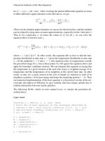
In IPv4, authentication information is carried in an authentication header
inserted between the Internet layer header and the transport layer header in the IP
datagram. In IPv6, the IP datagram consists of a base header, extension headers,
transport layer header, and message. The authentication header is one of the exten
-
sion headers. Figure 6.6 shows IPv4 and IPv6 datagrams that include authentication
headers. The information fields in the datagram are listed in Appendix B. The
authentication header provides data integrity through the use of keyed hashing.
Hash functions represent a variable-length message by a fixed-length data string.
The hashing algorithm is negotiated during SA setup. It provides address and pay
-
load integrity by hashing those entries in the IP header that do not change and the
entire payload. To provide additional security, IPsec can create new keys after a set
amount of data has been transferred or a certain time has elapsed.
When authentication and privacy are required, IPsec employs an encapsulating
security payload (ESP). ESP has three sections: an ESP header that is positioned
114 Protecting Enterprise Catenets
between the Internet header and the transport header, an ESP trailer that follows the
message, and an ESP authentication that follows the ESP trailer. Appendix B lists
the information fields in a datagram with ESP. Neither the authentication protocol,
nor ESP, fits the definition of tunneling given earlier in this section. True, they pro
-
vide authentication and/or encryption, but they do not wrap an encrypted datagram
inside another datagram so that it can be forwarded between two points over an
insecure temporary connection without making use of its contents.
IPsec defines tunneled versions of the authentication header and the encapsulat-
ing security payload. They are shown in Figure 6.7. Each contains the original IP
datagram encapsulated by a second Internet header that contains the IP addresses of
the tunnel ends. In addition, an authentication header or an ESP header is posi-
tioned next to the original datagram. An ESP trailer and ESP authentication field
follow the original datagram in the ESP tunneling datagram.
6.2.6 Other Tunneling Protocols
Industry groups have developed other tunneling protocols. Of note are:
•
Point-to-Point Tunneling Protocol (PPTP): A data link sublayer (Layer 2)
protocol that encapsulates PPP frames in IP datagrams for transmission over
an IP network. PPTP supports a single tunnel between client and server.
•
Layer 2 Tunneling Protocol (L2TP): A data link sublayer (Layer 2) protocol
that encapsulates PPP frames for transmission over IP, X.25, frame relay, or
ATM. L2TP supports multiple tunnels. L2TP combines the best features of
PPTP and L2F, an early product from Cisco Systems Corporation. When used
in an IP network, L2TP uses UDP for tunnel creation and transmission. Both
6.2 Combating Loss of Privacy 115
Internet
header
Authentication
header
Transport
header
Message
IPv4 datagram
Internet
header
Authentication
header
Transport
header
Message
IPv6 datagram
Extension
header #1
Extension
header #n
Figure 6.6 Authentication headers in IPv4 and IPv6 datagrams.
Encapsulating
header
Authentication
header
Original datagram D(1)
IPSec authentication tunneling datagram D(2)
ESP
authentication
ESP
header
ESP
trailer
Original datagram D(1)
IPSec encapsulating security payload tunneling
datagram D(2)
Encapsulating
header
Figure 6.7 IPsec tunneling mode datagrams.
tunneled data and control frames share the same UDP stream. L2TP uses IPsec
for cryptographic services. Figure 6.8 shows an L2TP datagram encapsulated
by PPP and encrypted by IPsec. The original datagram is wrapped in a PPP
frame. The PPP frame is then incorporated in a new IP datagram with a UDP
header and an L2TP header. Adding an IPsec encapsulating security payload
header and trailer and an IPsec authentication trailer provides message integ
-
rity and authentication. Finally, an IP header is attached that contains the net
-
work addresses of the beginning and ending of the tunnel.
6.2.7 Firewalls
In a catenet that has Internet connections, preventing eavesdropping, hacking, or
theft of information and controlling the amount and nature of internal traffic for
-
warded to Internet are a formidable task. Most schemes rely on establishing and
maintaining an electronic firewall, which is a software/hardware device that denies
unauthorized callers access to a private network, and controls calls from the private
network to destinations reached over the public network.
Situated between an intranet and the Internet, a firewall consists of screening
routers, dedicated servers, and computer logic that implement rules to determine
which connections are allowed and which are not. As noted in Section 6.2, the rules
are called proxies. They restrict the number of services available to outside connec-
tions and prevent the manipulation of services to provide unauthorized levels of
access. In addition, a firewall can be used to limit the flow of specific information to
callers from within the intranet and serve as the termination of tunnels through the
Internet.
Figure 6.9 generalizes the relationship between a firewall, a private network,
and the Internet. Conceptually, the firewall prevents the free exchange of data
frames between the private and public networks. If it compares favorably with one
or more databases managed by servers and meets other tests (if applicable), a data
frame will be passed around the wall. The internal router passes it on to the appro
-
priate subnetwork. For a catenet with several campus networks connected by the
Internet, a firewall is used to isolate each campus network from the Internet.
6.2.8 Functions Performed in Firewall
In Figure 6.9, a representative sampling is shown of the database and testing capa
-
bilities in the firewall servers and associated devices. For small networks, some can
116 Protecting Enterprise Catenets
IPSec/ESP
authentication
trailer
IPSec/ESP
trailer
Original datagram
IP
transport
header
TCP/UDP
header
Message
PPP
header
L2TP
header
UDP
header
IPSec/ESP
header
IP
transport
header
Encrypted with IPSec
Figure 6.8 L2TP encapsulation with privacy and authentication.
be combined, and not all of them may be necessary. In large networks, they may all
be individual units, and more may be necessary to handle special situations.
When a private network is connected to the Internet, it is usual for management
to be concerned about the time wasted by employees surfing the Web for personal
reasons. This concern leads to a request for a policy that only authorized users may
access the Internet. To implement this policy requires the manual entry of each
authorized user in a database. For a large user community, this can be a lot of work,
particularly if there is significant turnover. If dynamic IP addressing is in use (i.e.,
each station receives an address at the start of a session and is entitled to its use for a
fixed time), the procedure will be complicated by changes in station addresses. If the
station operator is changed frequently, the procedure may be complicated by
changes in usernames and passwords. If banning all http:// traffic is impossible, per
-
haps the best approach is to maintain activity logs and question excessive use or the
use of specific addresses.
Briefly, the functions that may be implemented at the firewall can be described
as follows:
•
Authentication: Knowing that the incoming message has not been changed on
its journey through the public network and that the sender is correctly identi
-
fied is important for incoming traffic. Knowing the correct identity of those
that make outgoing calls to use Internet services or contact persons is equally
important. Proxy and/or Remote Authentication Dial-In Service (RADIUS)
servers make appropriate tests on the data frames. They work with username
and password information and may challenge originating or terminating enti
-
ties to confirm information.
6.2 Combating Loss of Privacy 117
Proxy
NAT
DNS
IP Addresses
Web
Web activity
Authentication/RADIUS
Username and password
Extranet
Electronic
commerce
SMTP
FTP
Files
Private network
Internal router
Firewall
Internet
External router
ISP
Tunnel origin
and termination
cryptographic
arrangements
Figure 6.9 Concept of firewall and the functions it performs.