A Professional’s Guide to Data Communication in a TCP/IP World phần 7 pdf
Bạn đang xem bản rút gọn của tài liệu. Xem và tải ngay bản đầy đủ của tài liệu tại đây (470.89 KB, 27 trang )
In many loops, remote terminals (RTs) are set up at some distance from the wire
center. Here 96, 672, or some other number of channels are aggregated and trans
-
mitted over optical fibers between the MDF and the remote terminals. Called digital
loop carrier (DLC), the channels are distributed from the RTs to customers in the
carrier serving area (CSA) over distribution and drop cables. The carrier serving
area is limited to 9,000 feet from the RT. Any DSLs home on DSLAMs located at
the RT.
8.1.1.2 Optical Fibers in the Local Loop
In the local loop, carriers have installed fiber to carry multiplexed signal streams
close to their destination. They terminate in optical network interfaces (ONIs)
where twisted pairs are used to complete the connection to residences or small busi
-
nesses. Several acronyms are used to identify such installations:
•
FITL: fiber in the loop;
•
FTTC: fiber to the curb;
•
FTTH: fiber to the home.
They are used without precision to indicate various levels of fiber availability.
Most carriers are awaiting the development of demand for residential wideband
services before making major commitments to these facilities.
SONET rings are employed to connect the main switching center, remote
switches, remote terminals, distribution interfaces, and other traffic collection
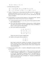
points. Figure 8.2 illustrates the principle of applying SONET in the local communi-
cation environment to replace feeder cables. In the figure, a star-star arrangement is
compared to ring-based structures that employ SONETs. The ring-bus structure is
constructed from the combination of cable television and incumbent local exchange
8.1 The Last Mile 147
Distribution
plant
SAP
Star–star
CO
Ring–bus
= Service access point (SAP)
SAP
Feeder
plant
Distribution
plant
Ring–star
Feeder
plant
Distribution
plant
Feeder
plant
SAP
SONET
SONET
Remote
switch
= Feeder distribution interface (FDI), or
Add-drop multiplexer (ADM)
FDI
ADM
ADM
Cable
Wire center
Figure 8.2 Alternative architectures for loop plant.
carrier (ILEC) facilities. The ring-star structure is constructed from ILEC facilities.
Both arrangements can provide voice, video, and data services.
8.1.2 Modems and Digital Subscriber Lines
For residential applications such as working-at-home and Internet, the bandwidth
of the data stream signals must be compatible with the bandwidth of the twisted pair
cable that links the user to the network. Substantial processing is required to match
the characteristics of the data signals to the line.
8.1.2.1 V.34 and V.90 Modems
Over the years, modem speeds have become faster and faster as designers have found
ways to achieve more bits per symbol, and more symbols per second. Standardized by
ITU, V.34 and V.90 are the latest in a long line of modems used on two-wire (twisted
pair) telephone lines. Adjusted at the time of use to yield reliable performance, V.34
uses a symbol rate between 2,400 baud and 3,429 baud. Employing QAM on both
channels of a duplex circuit, it can achieve bit rates of over 30 kbit/s. To prepare for
data transfer, V.34 executes a four-part setup routine. Users of V.34 modems who
listen during setup can hear them. The following is the four-part setup routine:
1. Network interaction: Exchange of signals with receiving modem to establish
that the circuit is ready.
2. Ranging and probing: Exchange of signals to establish symbol rate, round
trip delay, channel distortion, noise level, and final symbol rate selection.
3. Equalizer and echo canceler training: Exchange of signals designed to
optimize performance of the equalizers and echo cancellers in the send and
receive modem.
4. Final training: Exchange of known signals to establish setup is complete.
The V.90 modem makes use of V.34 technology in the upstream direction. In the
downstream direction it uses 128 special symbols to send at 56 kbit/s. Should the
line be unable to support this rate, the number of symbols is reduced with a conse
-
quent reduction in bit rate.
8.1.2.2 Digital Subscriber Lines
Digital subscriber lines (DSLs) provide a way to meet demands for high-speed serv
-
ices over existing telephone cable pairs. Moreover, DSLs can be used as alternatives
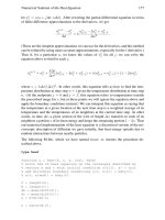
to traditional digital lines (such as T-1 and ISDN PRI). Figure 8.3 shows the concept
of using DSLs for residential and small business connections. In the central office,
DSL access multiplexers (DSLAMs) connect individual DSLs on twisted pairs to a
regional high-speed network that provides access to content providers and the Inter
-
net. At the CO, POTS services are split from the data signals and directed to the
PSTN. In the home, a similar splitting function is performed to separate telephone
traffic from data traffic. Taking advantage of significant advances in signal process
-
ing and solid-state technology, several types of DSLs have been deployed, and more
are in active development. The following sections give some indication of the equip
-
ment that is available.
148 The Convergence of Voice and Data
8.1.2.3 High-Bit-Rate Digital Subscriber Line
Before the ITU Recommendations for ISDN were formally adopted, attempts were
underway to simplify the provisioning of ISDN PRI services for local access. The
goal was operation over 26 AWG wire up to 9,000 feet, or 24 AWG wire up to
12,000 feet, without repeaters. Called high-bit-rate digital subscriber line (HDSL),
the DS-1 stream is split into two streams of 784 kbit/s (768 kbit/s for data, 8 kbit/s
for signaling, and 8 Kbits for control). Each is transported over a cable pair giving
rise to the term dual-duplex transmission. The elimination of repeaters results in
bit-error rates of approximately 10
–10
. This is equivalent to the error performance
of fiber optic systems.
For installations greater than 12,000 feet, repeaters (known as doublers) are
employed. With 24 AWG cable pairs, up to 24,000 feet can be reached with one
repeater, and up to 36,000 feet with two repeaters. For installations less than 3,000
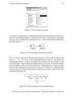
feet and greater than 36,000 feet, T-1 is used. Figure 8.4 shows the implementation
of HDSL with and without doublers. HDSL circuits are designed to assure one-way
signal transfer delay is less than 0.5 ms. With one mid-span repeater, the delay is less
than 1 ms. Delay is important because some upper layer protocols may time out due
to the total end-to-end delay.
8.1 The Last Mile 149
Figure 8.3 DSL network architecture.
8.1.2.4 HDSL2
HDSL2 complements HDSL. Sometimes, HDSL2 is called S–HDSL. S–HDSL is also
used to refer to the implementation of one-half HDSL (duplex 784 kbit/s on a single
pair). Operating over a single pair, HDSL2 provides T-1 speed over 26 AWG up to
12,000 feet. Transmission over a single pair of wires required the development of an
efficient spectral shaping signaling technique to minimize crosstalk between adja-
cent pairs that might be running ISDN, T-1, HDSL, or HDSL2. Known as over
-
lapped pulse–amplitude modulation with interlocked space (OPTIS), it supports
PAM, QAM, CAP, and DMT (see Appendix A) with overlapping downstream and
upstream bit streams. The current modulation format uses trellis-coded PAM with 3
bits per symbol and a 16-level constellation. The signaling rate is 517.3 kbaud.
8.1.2.5 Single-Pair High-Data-Rate Digital Subscriber Line
Single-pair high-data-rate digital subscriber line provides symmetrical services
between 192 kbit/s and 2.3 Mbps. Intended for applications such as ISDN, T-1,
POTS, frame relay, and ATM, it operates up to 24 kft on a 24 AWG loop. Called
G.shdsl, the modulation scheme is similar to HDSL2—trellis-coded PAM with 3
information bits per symbol (a 16-level constellation) and OPTIS spectrum shaping.
G.shdsl was standardized by ITU and ANSI.
8.1.2.6 Asymmetrical DSL (ADSL)
ADSL provides unequal data rates in downstream and upstream directions. In addi
-
tion, the lowest portion of the bandwidth is used for analog voice. ADSL modems
use two techniques to achieve downstream and upstream operation.
150 The Convergence of Voice and Data
Twisted pairs
HTU-R
HTU-C
784 kbits/s; 392 baud
Duplex
784 kbits/s; 392 baud
Duplex
CSU
DSL
AM
≤
≤
9000 feet, 26 AWG
12000 feet, 24 AWG
≤ 24000 feet, 24 AWG
( 36000 feet, 24 AWG, with 2 DRE)≤
Subscriber Central office
Subscriber Central office
Doubler
DRE
HTU-CHDSL Transceiver unit–central office
HTU-RHDSL Transceiver unit–remote
CSU Channel service unit
DSLAM Digital subscriber line access multiplexer
DREHDSL Ran
g
e extender
HTU-R
HTU-C
DSL
AM
CSU
Figure 8.4 HDSL implementation.
•
Frequency division multiplexing (FDM): By dividing the operating spectrum
into separate, nonoverlapping frequency bands, a voice channel and upstream
and downstream data channels are created. This eliminates self-crosstalk as
an impairment.
•
Echo cancellation (EC): The upstream and downstream channels overlap. This
necessitates using echo cancellers and retains self-crosstalk as an impairment.
ANSI specifies the use of DMT and two sets of operating rates for ADSL:
•
Downstream 6.14 Mbps, upstream 224 kbit/s, over 24 AWG cable pairs up to
12,000 feet;
•
Downstream 4 Mbps, upstream 512 kbit/s, over 24 AWG cable pairs up to
12,000 feet.
A later specification increased the downstream rate to 8.192 Mbps and the
upstream rate 640 kbit/s. These speeds are achievable over relatively new copper
installations. Available products use either DMT or CAP modulation.
Separating the voice channel from the data channels is achieved with highpass
and lowpass filters. The lowpass filter prevents the data streams from adversely
affecting the voice service, and the highpass filter prevents voice signals from
adversely affecting the data streams. The combination of filters is known as a split-
ter. They are installed at both ends of the subscriber line.
8.1.2.7 Spliterless ADSL (G.lite)
G.lite is a scaled-down version of ADSL that does not require splitters to separate
voice from data. This simplification makes installation by subscribers possible.
However, installation does require lowpass filters (microsplitters) on each tele-
phone. Spliterless ADSL is described as a best-effort transmission system. Achiev
-
able downstream/upstream data rates are 640/160 kbit/s to 18,000 feet, 1,024/256
kbit/s to 15,000 feet, and 1,512/510 kbit/s to 12,000 feet.
Ringing signals directed to a telephone connected to G.lite, and off-hook/on-
hook activity, can result in impedance changes that unbalance the DSL modem
operation and require modem retraining. During retraining, the modems are unable
to transmit data. To make retraining as fast as possible, G.lite modems store up to
16 operating profiles.
8.1.2.8 Very-High-Bit-Rate DSL (VDSL)
VDSL is an extension of ADSL technology to rates up to 52 Mbps downstream. The
configuration includes twisted pairs between subscribers and an optical network
unit (ONU). In turn the ONU is connected by fiber to the CO.
As stated earlier in this chapter, the differences between the performance of
DSLs reflects the year in which each was standardized and the capability of digital
electronics at the time. They represent the determination of owners of existing wire
plant to make it usable by those who want high-speed data capability.
8.1 The Last Mile 151
8.1.3 Cable Television
The demand for faster response over Internet has provided an opportunity for cable
companies to use part of their capacity for Internet access. Using MPEG compres
-
sion and QAM modulation, modern cable television systems can offer 10 digital
video channels in the 6-MHz bandwidth used by one analog television channel.
With a cable bandwidth of 550 MHz, they can provide around 900 separate video
channels to their customers. Assuming they have difficulty filling more than 500
channels with analog television, digital television, music, pay channels, and the like,
up to half of the cable can be used for data transport.
A unique feature of cable connections is they are always on. The user does not
have to wait for a connection to be established. To send data upstream from individ
-
ual users to the cable modem termination system (CMTS), time division multiplex
over a 2-MHz channel is employed. Each user has a private channel. The signals are
placed in the frequency band 5 to 42 MHz. To receive data from the Internet, a com
-
munity of as many as several hundred users shares one 6-MHz channel, Ethernet-
style, placed in the frequency band 42 to 850 MHz. Since the channel is capable of
up to 40 Mbps, if there are 10 users downloading data simultaneously, each can
expect to have an average downloading speed of up to 4 Mbps. With 100 users
downloading simultaneously, the average speed drops to 400 kbit/s. Like Ethernet,
throughput drops as the number of simultaneous users increases.
8.2 Voice over IP (VoIP)
Most of us employ two networks to meet our communication needs—the PSTN for
voice and Internet for data. In fact, many of us use the last mile of telephone com-
pany facilities to connect to an ISP to gain access to Internet. The PSTN and Internet
are quite different. Making one carry traffic more properly carried by the other
ignores the design and economic factors used to implement them and strains their
resources. For instance, Internet users expect the local telephone company to sup
-
port connections for many hours of Web browsing, and VoIP users expect the Inter
-
net to provide a steady, uniform stream of voice packets to support satisfactory
voice quality. The telephone company has designed its network around average calls
of a few minutes duration in the busy hour. It provides high-quality service and
numerous features. The Internet is a best-effort network that mixes packets from
many users and does not guarantee timely delivery. Indeed, they may not deliver
some packets at all.
Since the early 1970s, voice transmission has been the subject of experiments
mounted by ARPAnet users. They quickly showed that a virtual duplex circuit could
carry intelligible voice in packets. More recently, the Internet has been used to carry
voice between terminals operated by enthusiastic Web surfers. Such experiments
have stimulated activity in the communications vendor community. The next step,
implementation over enterprise IP networks (intranets), is underway. What remains
to be done to emulate the telephone companies is provide toll-quality voice with
intelligent network features all over the nation. However, carrying millions of calls
per hour and providing the kind of quality, features, security, and reliability that
telephone customers have come to expect causes the difficulties explode. Unfortu
-
152 The Convergence of Voice and Data
nately, providing good voice quality and extensive features is only an aspect of the
problem. It is much more difficult to create a signaling system that provides the
complex features needed by multimedia communications and interface them to the
international world. In this section, I discuss VoIP as a precursor of more exotic
services using Internet and PSTN.
8.2.1 Packet Voice
The output of a microphone, the transducer that converts sounds to electrical sig
-
nals, is a continuous value proportional to the air pressure exerted by the audio
source. Voice signals, then, are naturally analog signals. Before packet voice is cre
-
ated, the voice signal must be conditioned and digitized.
The quality of reconstructed coded voice is evaluated by a number of partici
-
pants in structured listening tests. The results are expressed as a mean opinion score
(MOS). Reconstructed speech that is not distinguishable from natural speech is
rated 5.0 (excellent). Other scores are 4 (good), 3 (fair), 2 (poor), and 1 (bad). Stu
-
dio quality voice has an MOS between 4.5 and 5.0. Sixty-four-kbit/s PCM voice is
known as toll quality voice and has an MOS of 4.3. Communication quality voice
(i.e., quality acceptable to professional communicators such as airline pilots, mili
-
tary personnel) has an MOS between 3.5 and 4.0. A score below approximately 3.5
is considered unacceptable for most applications.
8.2.1.1 Lower Bit Rate Coding
Sixty four-kbit/s PCM voice is robust and fully up to the exigencies of global tele-
phone service in which it may have to be coded and decoded a number of times
before reaching the final destination. Newer voice coding techniques encode PCM
samples to produce almost the same quality with far fewer bits per second. These
lower bit rate voice coders are complex devices. Most of them are hosted on special-
ized digital signal processors (DSPs). The additional processing means that they
impose significant delays on the coded voice stream. This may be troubling to some
users. Standardized by ITU, some of these voice coders are:
•
G 726: Uses adaptive differential PCM (ADPCM). Encodes voice to 32 kbit/s
with MOS of 4.0 and processing delay of 0.125 ms.
•
G 728: Uses low-delay code-excited linear prediction (LD-CELP). Encodes
voice to 16 kbit/s with MOS of 4.0 and processing delay of 0.625 ms.
•
G 729: Uses conjugate-structure algebraic-CELP (CSA-CELP). Encodes voice
to 8 kbit/s with MOS of 4.0 and processing delay of 15 ms.
•
G 723.1: Uses algebraic-CELP (ACELP). Encodes voice to 6.3 kbit/s with
MOS of 3.8 and processing delay of 37.5 ms.
For comparison, PCM voice is standardized as G711, which uses PCM and
encodes voice to 64 kbit/s with an MOS of 4.3 and a processing delay of 0.125 ms.
By using lower bit rate coding, fewer packets are needed to contain a given
amount of speech. At 64 kbit/s, each second of speech requires approximately 167
ATM cells (payload 48 bytes/cell). At 7 kbit/s, each second of speech requires
approximately 18 cells. For VoIP, G 723.1 uses fewer packets than G 729 with
8.2 Voice over IP (VoIP) 153
lower voice quality and significantly more processing delay. G 729 uses some 13%
more packets than G 723.1 with 5% better voice quality and less than one-half the
processing delay. As a reference point, the one-way delay in a geostationary satellite
channel is 250 ms. It is noticeable by everyone and is sufficient to cause users signifi
-
cant frustration unless echo cancellers are employed. Delays up to 100 ms are
tolerated by most people. Presumably, we shall see further voice coder improve
-
ments in the future.
8.2.1.2 Packet Size, Delay, and Loss
Interactive data requires two simplex channels. One links the send port on terminal
1 to the receive port on terminal 2; and the other links the send port on terminal 2 to
the receive port on terminal 1. While one link may carry data in response to a com
-
mand on the other link, the exact positioning of the response relative to the com
-
mand is not important. The size of the packet affects the size of the buffer that has to
be reserved (at both ends), and the delay incurred in receiving the packet. It does not
affect the quality of the exchange. In addition, errored or lost packets are of little
consequence since they can be retransmitted and folded into the sequence or used
out of sequence.
VoIP is implemented on a duplex circuit. To support a conversation, the timing
of the speech on both channels is important. The rhythm of the give and take of a
conversation must not be compromised. In addition, packets must arrive on time so
that the samples they carry can be used to reconstruct a waveform that contains
something close to the original frequencies. If it does not, the participants will not
feel natural, and their words may be unintelligible at times. Conversationalists have
limited tolerance for delay, and fluctuations of delay. Both the end-to-end average
delay, and the end-to-end variation of delay, should be small. The successful trans-
mission of Vo IP depends on controlling the mean and variance of packet delay over
each channel, and controlling the offset delay between the channels. Packet speech is
particularly vulnerable to tails in the delay distribution (i.e., random occurrence of
long delays). To mitigate their effect, the size of the receiver buffer can be increased.
This increases mean delay, but reduces the variance.
Received speech is interrupted and distorted by losing or discarding (due to con
-
gestion, perhaps) packets. The severity depends on the packet size. It is generally
believed that losses as high as 50% can be tolerated if they occur in very short inter
-
vals (less than 20 ms). Intelligibility of 80% is said to occur when the packet size is
20 ms and 10% when the packet size is 200 ms. The optimal packet length is gener
-
ally accepted to be somewhere between 25 and 75 bytes. It is not just a coincidence
that ATM cell relay employs payloads of 48 bytes.
8.2.2 Telephone Signaling
As pointed out earlier, the principle of VoIP is well established; on a private scale, it
is implemented successfully. To implement VoIP on a public, national scale is a dif
-
ferent matter. Figure 8.5 shows the equipment involved in setting up a long-distance
voice call between parties using wire-line facilities. The calling party initiates call
setup by signaling over the local loop with tones (DTMF). At the Class 5 central
office, signaling is transferred to a digital, common-channel system that makes the
154 The Convergence of Voice and Data
request known to a toll/tandem office. Here, the signaling and calling paths are
separated. The request moves into the Signaling System #7 (SS7) network in packet
form. The combination of signal transfer points (STPs) and network control points
(NCPs) in SS7 find a path through the voice network to the toll/tandem serving the
called party. Ideally, the available path includes a single, dynamic nonhierarchical
routing (DNHR) tandem switch. If the called party’s line is not in use, the voice con
-
nection is set up through the calling CO, the calling toll/tandem, the connecting
DNHR tandem, the called toll/tandem, and the called CO. IN features such as call
-
ing number ID may be activated. If the called party’s line is busy, IN features such as
call waiting, call forwarding, and voicemail may be invoked. Adjunct service points
(ASPs) and signaling control points (SCPs) in the intelligent network implement
them as appropriate.
8.2 Voice over IP (VoIP) 155
TDM signal
Users
STP
STP
STP STP
NCP
NCP
Toll/tandem
CO
Class 5
NAP (IN)
DNHRTandem
ASP
ASP
Toll/tandem
ASP
ASP
Users
SCP
SCP
ASP Adjunct Processor (IN)
CO Central Office
DNHR Dynamic Non-Hierarchical Routing
DTMF Dual-Tone Multi-Frequency Signaling
IN Intelligent Network
NAP Network Access Point (IN)
NCP Network Control Point
SCP Services Control Point (IN)
SS7 Signaling System #7
STP Signal Transfer Point
Analog signal
associated
in-band
signaling
(DTMF)
TDM signal
associated common
channel signaling
Inter-office disassociated
common channel
signaling SS7
packets
TDM signal
Signal transfer points
are duplicated and
fully connected
IN
IN
IN
IN
IN
IN
CO
class 5
NAP (IN)
Telephone
Modem
Facsimile
Network Control Points provide
number changing and routing
information
Local Loop Local loop
Figure 8.5 DTMF, common channel and SS7 signaling in telco network with intelligent network
features.
Transporting the caller’s voice and the response of the called party between
originating and terminating terminals is straightforward. Setting up and managing
the call requires a significant amount of processing power; adding IN features
requires even more. Multiply it by 100 or 200 million telephones, of which perhaps
10 million are active simultaneously, add many tens of carriers, and you begin to see
the magnitude of a national VoIP network.
8.2.3 Real-Time Transport Protocols
Meanwhile, several protocols have been developed to support the real-time delivery
of voice packets. They work in conjunction with signaling protocols (see Section
8.2.4). Once the connection has been made, they present (or receive) compressed
voice segments to (from) the TCP/IP stack. Of note are:
•
Real-Time Transport Protocol (RTP): Interfaces between the voice stream and
existing transport protocols (UDP or TCP). RTP provides end-to-end delivery
services for audio (and video) packets. Services include source and payload
type identification (to determine payload contents), sequence numbering (to
evaluate ordering at receiver), time stamping (to set timing at receiver during
content playback), and delivery monitoring. RTP is run on top of UDP or
TCP. RTP does not address resource reservation, or guarantee delivery, or pre-
vent out-of-sequence delivery.
•
RTP Control Protocol (RTCP): A protocol that monitors QoS based on the
periodic transmission of control packets. RTCP provides feedback on the
quality of packet distribution.
•
Real-Time Streaming Protocol (RTSP): An application level protocol that
compresses audio or video streams and passes them to transport layer proto-
cols for transmission over the Internet. RTSP breaks up the compressed data
stream into packets sized to match the bandwidth available between sender
and receiver. At the receiver, the data stream is decompressed and recon
-
structed. Because of the compression and decompression actions, the received
quality is unlikely to be equal to the original.
8.2.4 Major Signaling Protocols
The virtual circuit for VoIP is established by signaling protocols. They provide basic
telephony features and IN items. Three signaling protocols are competing to pro
-
vide VoIP services. They are ITU’s Recommendation H.323, Session Initiation
Protocol (SIP), and Multimedia Gateway Control Protocol (MGCP). Their relation
and the relation of the media transport protocols to the IP stack are shown in
Figure 8.6.
8.2.4.1 Recommendation H.323
H.323 is an ITU-developed multimedia communications recommendation that
offers audio, video, and facsimile services over LANs. It does not guarantee QoS lev
-
els. Focusing on voice services, it provides connections for moderate numbers of
users and is incorporated in commercial offerings. As an implementer of VoIP,
156 The Convergence of Voice and Data
H.323 allows the calling and called parties to use their telephone experience includ
-
ing call forwarding, call waiting, and call hold. It is an application-level protocol
that mediates between the calling and called parties and the end-to-end transport
protocol layer. H.323 uses RTP and RTCP for transport. In Figure 8.6, I have tried
to distinguish the domain of H.323 call set up functions and the domain of RTP call
transport functions. The general flow of a two-party voice call is as follows:
1. The user goes off-hook, causing the call setup protocol of H.323 to issue a
dial tone and wait for the caller to dial a telephone number.
2. The dialed numbers are accumulated and stored.
3. After the digits are received, the number is correlated with an IP host that
has a direct connection to the destination telephone number or a PBX that
will complete the call.
4. The call setup protocol establishes a duplex virtual circuit (using TCP) over
the IP network.
5. If a PBX handles the call, the PBX forwards the call to its destination.
6. If RSVP is configured, resource reservations are made to achieve the desired
QoS.
8.2 Voice over IP (VoIP) 157
Figure 8.6 TCP/IP stack with VoIP protocols.
7. Call-progress indications (ringing, busy, and other signals that are carried
in-band) are carried over the IP network encapsulated in RTCP.
8. Codecs are invoked at both ends of the circuit to provide low bit rate voice,
and the call begins.
9. RTCP monitors performance and provides feedback to RTP.
10.When the parties go on-hook, the RSVP resource reservations are canceled
and the session ends. H.323 becomes idle waiting for the next off-hook
signal.
Originally developed to facilitate multimedia communications over local area
networks, H.323 operates independently of network topology. Today, most imple
-
mentations use H.323 with RTP/UDP/IP for speed and simplicity over any IP net
-
work. H.323 was an early starter in the VoIP race. Because it is sponsored by ITU, it
has experienced wide dissemination and exploitation.
8.2.4.2 Session Initiation Protocol (SIP)
SIP is a signaling protocol developed to facilitate telephone sessions and multimedia
conferences in a unicast or multicast private network environment. Through gate-
ways, SIP communicates with public terminals, and provides a limited menu of IN
services. In addition, it can connect with private networks that employ H.323, or
other signaling protocols. In VoIP use, SIP operates much like the scenario given for
H.323. It is claimed to be faster, simpler, and more scalable than H.323.
Developed by a committee of the IETF, SIP uses text-like messages. It does not
use other protocols such as RTP, RSVP, and so forth. SIP responds to telephone
numbers or URLs and negotiates the features and capabilities of a call prior to setup.
It can modify them during the course of a session.
8.2.4.3 Media Gateway Control Protocol (MGCP)
MGCP is a commercial/IETF development designed to facilitate multimedia sessions
between the Internet and the PSTN. The media gateway (MG) acts between the two
networks to translate media streams from circuit-switched networks into packet-
based streams, and vice versa. MG components may be distributed among several
network devices. MGCP employs a series of commands written in ASCII code that
contain an action verb (e.g., create, modify, delete, and so forth) and supporting
data. The destination station acknowledges each command and may respond with
information; the sender correlates any response with the enabling command.
8.3 Final Word
The needs in business and residential markets to have both voice and data (and lim
-
ited video services) have produced the concept of the convergence of voice and data
networks into one that offers multimedia broadband services. Data enthusiasts see
the eventual triumph of packet techniques and the replacement of the PSTN by an
expanded and improved Internet. For this to happen, their technology push must be
converted into market pull. Meanwhile, the owners of hundreds of billions of dol
-
158 The Convergence of Voice and Data
lars worth of legacy systems—the PSTN companies—will develop counter strategies
that continue to recoup their investments and provide competing services. It is likely
that multimedia broadband services will evolve from the combination of the two
networks rather than by one replacing the other.
Communication by electrical, electronic, and optical means is an important, and
essential, part of modern life. Global commerce depends on it. Take away the ability
to generate data in one place, process it into information in another, and use it any
-
where, immediately, and the world economy will slow dramatically. So, too, will the
lives of the Internet generation. E-mail, the Web, and pervasive communications
from the computer keyboard have permeated the very core of humankind. Between
the more than 200 million computers connected to Internet, TCP/IP is the only suite
of communication protocols in use. Does anyone doubt its dominance over all oth
-
ers? It makes the Internet what it is, an immensely successful, worldwide, digital
communication network.
8.3 Final Word 159
.
APPENDIX A
Connections, Codes, Signals, and Error
Control
Throughout this book, I have assumed a certain amount of communication knowl
-
edge on the part of the reader. For those who need a refresher, several topics are dis
-
cussed in this appendix.
A.1 Connections
A connection may provide one- or two-way message transport. The former is
known as a channel and the latter is known as a circuit.
•
Channel: A unidirectional communication path;
•
Circuit: A bidirectional communication path. Can be considered to be two
channels operating simultaneously (one in each direction).
Furthermore, communication can occur in three ways:
•
It can be in the style of an announcement with information flowing in one
direction and no reply possible.
•
It can be interactive with the participants exchanging information as neces-
sary (sometimes at the same time).
•
It can be in the style of a debate with the participants addressing each other in
turn.
While these examples are personal, they are close matches to the ways in which
machines communicate. The connections that support them are identified as follows:
•
Simplex: Supports announcement-style communication. Messages flow in one
direction only—from sender to receiver. Simplex employs a channel.
•
Duplex (sometimes called full-duplex): Supports interactive communications.
Messages can flow in two directions at the same time. Duplex employs a cir
-
cuit. The term full-duplex is used to distinguish a full-time, two-way circuit
from a half-duplex connection.
•
Half-duplex: Supports debate-style communication. Messages can flow in
both directions, but only in one direction at a time. Many local area networks
161
are half-duplex—stations receive and transmit, but only one action can occur
at a time. Half-duplex employs a single channel if it can be used in either direc
-
tion, or a circuit in which only one side is used at a time.
In addition, other arrangements in which multiple circuits are operated in paral
-
lel, have been implemented, for example, dual-duplex, which is a connection with
two duplex circuits on which signals are divided by frequency. The composite pro
-
vides twice the bandwidth of a single circuit. Dual-duplex is used to provide 1.544
Mbps over two twisted pairs for ISDN and HDSL.
A.1.1 Addresses
Addresses are described as:
•
Unicast: The address of a single station. Used in point-to-point
communication.
•
Multicast: An address that is shared by several stations. Used in point-to-many
communication.
•
Broadcast: An address that is processed by every station on the same segment
of the network. Routers do not pass broadcast messages to other networks.
A.2 Codes, Code Words, and Code Sets
Binary symbols are known as bits, and sometimes as binits. Bits and binits are con-
tractions of the words binary digits. When necessary, the term binit is used to distin-
guish between a binary digit and a symbol in information theory that has a 50%
probability of being sent (and is therefore invested with 1 bit of self-information).
Because a binary symbol can have only two values, it is used in groups of n bits. Each
n-bit group (called a code or code word) contains a code set of 2
n
unique codes (bit
patterns). For transmission between originating (sending) and terminating (receiv
-
ing) equipment, the code words are assembled in a stream that contains message,
control, and perhaps padding, code words. To communicate, any devices in the
communication path must know the meanings of the control codes, and the origi
-
nating and terminating devices must know the meanings of the message, control,
and padding, codes.
A.2.1 Code Word Length
With a set in which the code words are of equal length, the receiver’s task of break
-
ing the stream into words is as easy as counting groups of n bits. As long as the
receiver can count accurately and a reliable start indication is available, it can divide
the stream into code words for processing. In applications where the codes occur
randomly and all the code words in the code table (i.e., 2
n
) are in use, equal length
code words achieve maximum efficiency in terms of bits/character. Alphanumeric
codes do not meet these conditions. For instance, there will be one or more vowels in
every text word so that the use of codes that represent vowels far exceeds those that
represent consonants. Furthermore, since uppercase letters occur mostly at the
162 Connections, Codes, Signals, and Error Control
beginning of sentences, uppercase letter codes will be used infrequently. In addition,
punctuation marks and other text symbols are relatively rare. Nevertheless, equal
length codes are used in all general-purpose applications.
A.2.2 Some Popular Codes
Some popular codes are the following:
•
ASCII code: A 7-bit code standardized by ITU as International Telegraph
Alphabet #5 (ITA#5), ASCII contains 128 (i.e., 2
7
) code words. They permit
the designation of code words as letters (uppercase and lowercase), numbers,
punctuation, and control. In Table A.1 72 ASCII codes are shown. The
remaining 56 codes are used for punctuation and for additional control pur
-
poses. ASCII is the coding scheme used almost universally with personal com
-
puters and other devices such as keyboards, printers, and the like. Most often,
7-bit ASCII code is converted to 8-bit code by the addition of a parity bit to
check the correctness of transmission.
•
EBCDIC: An 8-bit code developed and used by IBM in all of its larger com
-
puters. Table A.2 shows 72 of 256 (i.e., 2
8
) EBCDIC characters. The remain-
ing 184 are used for punctuation, other text-related functions, and special
functions defined by the user.
A.2 Codes, Code Words, and Code Sets 163
Table A.1 Some Members of American Standard Code for Information Interchange
Alphas ASCII Alphas ASCII Numerics ASCII
a 1100001 A 1000001 0 0110000
b 1100010 B 1000010 1 0110001
c 1100011 C 1000011 2 0110010
d 1100100 D 1000100 3 0110011
e 1100101 E 1000101 4 0110100
f 1100110 F 1000110 5 0110101
g 1100111 G 1000111 6 0110110
h 1101000 H 1001000 7 0110111
i 1101001 I 1001001 8 0111000
j 1101010 J 1001010 9 0111001
k 1101011 K 1001001
l 1101100 L 1001100 Control ASCII
m 1101101 M 1001101 SYN 0010110
n 1101110 N 1001110 SOH 0000001
o 1101111 O 1001111 STX 0000010
p 1110000 P 1010000 ETX 0000011
q 1110001 Q 101001 EOT 0000100
r 1110010 R 1010010 ENQ 0000101
s 1110011 S 1010011 ACK 0000110
t 1110100 T 1010100 NAK 0010101
u 1110101 U 1010101 DLE 0010000
v 1110110 V 1010110 ETB 0010111
w 1110111 W 1010111
x 1111000 X 1011000
y 1111001 Y 1011001
z 1111010 Z 1011010
Format
MSB
xxxxxxx
LSB
•
Universal character set (UCS): Also known as unicode. A 16-bit code intended
to support all world languages, particularly Chinese, Japanese, and Korean.
65,536 (i.e., 2
16
) code words are available.
A.2.3 Parity Bits
To provide a check on the integrity of transmission, a parity bit may be added to
ASCII characters. Its value is determined by the number of ones (odd or even) in the
character and whether odd parity or even parity is employed:
•
Odd parity: If the number of 1s in the character is odd, the parity bit is 0 so
that the number of 1s in the character plus the parity bit remains odd. If the
number of 1s in the character is even, the parity bit is 1 so that the number of
1s in the character plus parity bit is odd.
•
Even parity: If the number of 1s in the character is odd, the parity bit is 1 so
that the number of 1s in the character plus parity bit is even. If the number of
1s in the character is even, the parity bit is 0 so that the number of 1s in the
character plus parity bit remains even.
Should a bit error occur subsequent to the addition of the parity bit, the wrong
parity state will exist and the receiver will declare an error is present. In fact, the par
-
164 Connections, Codes, Signals, and Error Control
Table A.2 Some Members of Extended Binary Coded Digital Interface Code
Alphas EBCDIC Alphas EBCDIC Numerics EBCDIC
a 10000001 A 11000001 0 11110000
b 10000010 B 11000010 1 11110001
c 10000011 C 11000011 2 11110010
d 10000100 D 11000100 3 11110011
e 10000101 E 11000101 4 11110100
f 10000110 F 11000110 5 11110101
g 10000111 G 11000111 6 11110110
h 10001000 H 11001000 7 11110111
i 10001001 I 11001001 8 11111000
j 10001010 J 11001010 9 11111001
k 10001011 K 11001011
l 10001100 L 11001100 Control EBCDIC
m 10001101 M 11001101 SYN 00110110
n 10001110 N 11001110 SOH 00000001
o 10001111 O 11001111 STX 00000010
p 10010000 P 11010000 ETX 00000011
q 10010001 Q 11010001 EOT 00110111
r 10010010 R 11010010 ENQ 00101101
s 10010011 S 11010011 ACK 00101110
t 10010100 T 11010100 NAK 00111101
u 10010101 U 11010101 DLE 00010000
v 10010110 V 11010110 ETB 00100110
w 10010111 W 11010111
x 10011000 X 11011000
y 10011001 Y 11011001
z 10011010 Z 11011010
Format
MSB
xxxxxxxx
LSB
ity bit will detect one, three, five, or seven errors (i.e., all odd numbers of errors) in
the character. However, the parity bit will not detect two, four, and six errors (i.e.,
all even numbers of errors) in the character. Parity checking is also known as verti
-
cal redundancy checking (VRC).
A.2.4 Bit Order
The code words in Tables A.1 and A.2 are treated as binary numbers. The bit order
is important. The least significant bit (LSB) is on the right end of each word, and the
most significant bit (MSB) is on the left end. For ASCII with parity and EBCDIC, the
codes are 8-bit groups for which the bit positions are numbered as follows:
MSB
76543210
LSB
In ASCII with parity, position 7 contains the parity bit, and positions 0 through
6 contain the character. In common with computer usage, an 8-bit group is called a
byte. How do we read bytes into a serial stream? There are two ways to do it. We
may read from the LSB to the MSB or from the MSB to the LSB. Is one way better
than the other? No, they are equally effective. In fact, both methods are in use. For
instance, in an Ethernet local area network, the letter a, which, in ASCII is
MSB
1100001
LSB
will be read into the data stream as
⇐1000011
In a Token Ring local area network, it will be read into the data stream as
⇐1100001
Ethernet is said to employ little Endian or canonical format and Token Ring is
said to employ big Endian format:
•
Little Endian or canonical format: Bits are read in ascending order from the
least significant bit to the most significant bit. Bytes are numbered left to right,
from 0 to N, and are read in ascending order.
•
Big Endian format: Bits are read in descending order from the most significant
bit to the least significant bit. Bytes are numbered left to right, from 0 to N,
and are read in ascending order.
Figure A.1 shows the difference between these formats for a group of 6 bytes.
The little Endian strategy results in a stream consisting of bits:
⇐0→7, 8→15, 16→23, 24→31, 32→39, 40→47
The big Endian strategy results in a stream consisting of bits:
⇐7→0, 15→8, 23→16, 31→24, 39→32, 47→40
A.2 Codes, Code Words, and Code Sets 165
Obviously, to decipher the data stream correctly, it is important to know which
strategy has been employed.
In a digital voice network, an 8-bit group that represents the magnitude of a
sample of a voice signal is called an octet. Bit #7 indicates whether the value defined
by bits 0 through 6 is positive (1) or negative (0). Bit #7 is always transmitted first. In
this book, to avoid making the distinction and bowing to general practice, all 8-bit
words are called bytes.
A.2.5 Block Coding
To fine-tune the performance of the electronics and the data stream, block codes are
used. For instance, 1000BASE-X Ethernet employs 8B/10B coding. Each byte is sub
-
stituted by a 10-bit code word so that the 256 unique bytes are replaced by 256 of
the 1,024, 10-bit code words. The words are chosen so that they never contain fewer
than four 1s or four 0s and have a 1s/0s imbalance of no more than two. The code
words consist of four 1s and six 0s, five 1s and five 0s, or six 1s and four 0s.
In addition to the first 256, 10-bit code words, a second set is defined. They are
the bit inverse of the first set. Together, the first code word and its alternate contain
ten 1s and ten 0s. To maintain a balance between 1s and 0s in the bit stream, the
transmitter maintains a tally of whether more 1s than 0s or more 0s than 1s have
been transmitted. Called the running disparity (RD), its value determines whether
the transmitter selects the next code word as the one with more 1s than 0s, or the
alternate with more 0s than 1s. Code words that contain five 1s and five 0s will not
change RD. Its value remains constant until presented with the next unbalanced pair
of code words. The remaining 512 10-bit code words in the 1,024-word code space
are used to encode special functions.
166 Connections, Codes, Signals, and Error Control
0
7
8
15 16
23
24
31 3239
40
47
byte 0 byte 1 byte 2 byte 3 byte 4 byte 5
1st bit read (LSB of Byte 0)
48th bit read (MSB of Byte 5)
Start
End
7 0 15 8
23 16
31 24
39 32
47 40
Little endian bit order
Byte order
Bit order
7
0
15
8
23 16 31 24 39
32 47
40
1st bit read (MSB of Byte 0)
48th bit read (LSB of Byte 5)
Start
End
Big endian bit order
MSB MSB MSB MSB MSB MSBLSB LSB LSB LSB LSB LSB
MSB Most significant bit LSB Least significant bit
Figure A.1 Big Endian and little Endian bit order.
A.2.6 Scrambling
Certain patterns of data produce constant level signals that can be troubling to
transmission systems. For instance, strings of 0s may cause the terminals to lose syn
-
chrony. Other patterns can be equally as bad (e.g., strings of alternating 1s and 0s in
the case of 2B1Q). To avoid these effects, many transmission systems scramble the
bit stream before producing the physical signal. Figure A.2 shows the principle of
scrambling. By performing logical operations on the bit stream at the transmitter,
strings of the same symbol, or repeated patterns of symbols, are broken up and ren
-
dered pseudorandom. At the receiver, by repeating the logical changes, the scram
-
bled sequence is descrambled and the original data stream is restored. Because it is
automatic and completely reversible, scrambling is transparent to the sender and the
receiver. It is widely used on long-distance connections.
A.2.7 Hexadecimal Representation
Because writing 8-bit bytes can be tedious and subject to errors, hexadecimal nota
-
tion is used to represent them. Bytes are divided into two 4-bit binary words (4 bits,
or half a byte, is known as a nibble), whose decimal values (0 to 15) are represented
by the digits 0 through 9 and the letters A through F. Table A.3 shows the complete
representation. As an example,
01111110 = 0111,1110 = 0 × 7E
The symbols 0x are used to mean hexadecimal. Other examples are:
10101010 = 0 × AA; 10101011 = 0 × AB; and 00100000 = 0 × 20
A.3 Operating Modes
Code words are sent individually (asynchronously), or as part of a frame (syn-
chronously). The former mode is generally employed with keyboards and other
A.3 Operating Modes 167
Figure A.2 Principle of scrambling.
human/machine interaction devices at the edges of the network. The latter is
employed universally by equipment within the network.
A.3.1 Asynchronous Operation
An asynchronous operation is an operation in which characters are framed by start
and stop bits and sent as they are generated. A straightforward example of asynchro
-
nous operation is my use of a keyboard to input words into a data file in my personal
computer (PC). As I type each character, use the space bar to separate words, or hit
the enter key to form paragraphs, unique ASCII text and control codes are transmit
-
ted to my PC. Because I type at different speeds, the code words are generated at
irregular intervals. Each word consists of 8 physical bits whose pulse shape and repe
-
tition rate is tightly controlled. To let the receiver know what is going on, a start bit
is added to the beginning of the character, and a stop bit is added to the end. Tradi-
tionally, start bits are 0s and stop bits are 1s. In many cases, 2 stop bits are sent to
emphasize the end of the word. Thus, ASCII a with parity bit P will be entered into a
little Endian bit stream as:
⇐S1000011Pss
where S = start bit and s = stop bit.
A.3.2 Synchronous Operation
Synchronous operation is an operation in which a fixed number of characters are
assembled in sequence without start and stop bits. To the sequence a header is added
in front and a trailer is added at the rear to form a frame. (In some cases, the header
or the trailer is omitted.)
Figure A.3 shows the arrangement of a simple frame. The header indicates the
start of the frame and contains the address of the destination, if needed. The trailer
contains information with which to check for errors and indicates the end of the
frame. As noted earlier, the header and/or trailer fields may be omitted in some cir
-
cumstances. In other modes of operation they will contain additional information
needed to support the style of operation in progress. Synchronous operation is
implemented in two ways depending on whether synchrony between the receiver
and the incoming frame is achieved by internal or external means.
A.4 Signals
It is easy to get lost in the logic of digital communication and forget that communica
-
tion cannot occur until signals are generated and dispatched. A basic understanding
168 Connections, Codes, Signals, and Error Control
Table A.3 Hexadecimal Codes
0 = 0000 1 = 0001 2 = 0010 3 = 0011
4 = 0100 5 = 0101 6 = 0110 7 = 0111
8 = 1000 9 = 1001 A = 1010 B = 1011
C = 1100 D = 1101 E = 1110 F = 1111
Format
MSB
xxxx
LSB
of the types of signals can help explain some of the engineering mystery surrounding
the physical layer.
A.4.1 Signal Classification
Signals are classified by the way in which their values vary over time, thus:
•
Analog: A continuous signal that assumes positive, zero, or negative values.
Changes occur smoothly and rates of change are finite.
•
Digital: A disjoint signal that assumes a limited set of positive, zero, or nega-
tive values. Changes of value are instantaneous, and the rate of change at that
instant is infinite—at all other times it is zero. In practice, they are pulse-type
signals with finite rise and fall times. The peaks assume a limited set of posi-
tive, zero, or negative values.
•
Binary: A digital signal that has two values.
Analog, digital, and binary are concepts that allow us to divide the communica-
tion world into classes that require different technical procedures. In addition, sig-
nals may be divided by the degree of certainty with which their behavior is known:
•
Deterministic: At every instant, a deterministic signal exhibits a value that is
related to values at neighboring times in a way that can be expressed exactly.
Because determinism requires knowledge in the future as well as the past,
deterministic signals only exist in academic exercises where they are analyzed
using classical methods.
•
Probabilistic: A signal whose future values are described in statistical terms
based on past values. Probabilistic signals come closer to the real world. They
include uncertainty, but still require some relation between the past and the
future.
•
Random: A probabilistic signal whose values are limited to a given range.
Over a long time, each value within the range will occur as frequently as any
other value. True randomness is almost impossible to attain. Nevertheless,
many of the parameters contained in performance specifications are based on
random occurrences.
Furthermore, signals are classified according to their bandwidth, which is a
measure that is applied to frequency-limited signals (i.e., signals whose energy exists
within a specific frequency band and nowhere else). Bandwidth is the difference (in
A.4 Signals 169
Figure A.3 Components of the frame.
hertz) between the highest frequency at which signal energy is detected and the low
-
est frequency at which signal energy is detected.
For analog signals, bandwidth is measured at some point such as 3 dB or 6 dB
down from the signal peak. The decibel (dB) is a logarithmic measure of power ratio.
Three dB corresponds to a power level that is one-half of maximum power. Six dB
corresponds to a power level that is one-quarter of maximum power. For binary sig
-
nals, the sharp changes in values give rise to energy throughout the frequency spec
-
trum. Consequently, bandwidth is not easy to measure. Instead, it is stated in terms
of the bit rate. Binary signals are loosely classified as follows:
•
Narrow band(width): Up to 1.544 Mbps (T-1);
•
Wide band(width): 1.544 Mbps to 44.736 Mbps (T-3);
•
Broad band(width): Above 44.763 Mbps.
In addition, position with respect to the frequency axis is used to distinguish
between signals:
•
Baseband signal: An original unprocessed message signal. The energy it con
-
tains occupies a frequency band that may include 0 Hz (i.e., dc level). The
energy of a baseband signal occupies a fixed, unchanging position in the fre-
quency domain.
•
Passband signal: A complex signal produced by using a baseband signal to
modify a property of another signal (called the carrier signal). The energy of
the passband signal occupies a range (the passband) that encompasses the fre-
quency of the carrier signal, or is contiguous with it. The sideband components
of the passband signal carry the information contained in the baseband signal.
A passband signal may be moved in the frequency plane by changing the fre-
quency of the carrier signal.
A.4.2 Baseband Signal Formats
Several digital baseband signal formats are in common use. Examples are shown in
Figure A.4. They all represent the same bit sequence (101100111000). They are:
•
Nonreturn to zero (NRZ): A positive current represents 1 and zero current
represents 0. Sometimes called unipolar signaling, NRZ is used in integrated
circuit chips and other circuits, as well as in Gigabit Ethernet. Reliable timing
information can be obtained from the signal provided some minimum number
of bit transitions occurs in the data stream.
•
Nonreturn to zero, invert on ones (NRZI): Alternating positive and zero cur
-
rents represent 1. The same current as the previous 1 represents 0. Put another
way, the signal is unchanged for 0, and changes from its previous state for a 1.
The strategy of inverting on ones produces a narrower frequency spectrum
than NRZ. NRZI is used in FDDI and 100BASE-FX Ethernet.
•
Multilevel threshold-3 (MLT-3): A sequence of positive, zero, and negative
currents represent 1. The same current as the previous 1 represents 0. MLT-3
is a bipolar version of NRZI.
170 Connections, Codes, Signals, and Error Control
•
Biphase or Manchester: A positive current pulse of width one-half time slot,
which changes to a negative current pulse of equal magnitude and width one-
half time slot, represents 1. A negative current pulse of width one-half time
slot, which changes to a positive current pulse of equal amplitude and width
one-half time slot, represents 0. The changeover occurs exactly at the middle
of the time slot, so that the signal is always zero-mean. Furthermore, because
the level changes in each bit position, recovering a reliable timing signal is
guaranteed. This convenience is bought at the expense of a frequency spec
-
trum that is twice as wide as that of NRZ. Manchester is a popular signaling
technique for short links between high-speed equipment, and is used in
10-Mbps Ethernet systems.
•
Alternate mark inversion (AMI): Return-to-zero current pulses that alternate
between positive and negative represent 1. The absence of current pulses rep
-
resents 0. Thus, long strings of 0s produce no current. By changing the polar
-
ity of a pulse (from what it should be), a violation is created. In this way,
A.4 Signals 171
Figure A.4 Examples of binary signal formats.