A Professional’s Guide to Data Communication in a TCP/IP World phần 8 ppt
Bạn đang xem bản rút gọn của tài liệu. Xem và tải ngay bản đầy đủ của tài liệu tại đây (358.86 KB, 27 trang )
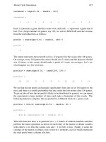
nique is known as quadrature amplitude modulation (QAM). The parameters of the
four symbols are shown in the center of Figure A.6. Such a diagram is known as a
constellation. Each symbol is a 270° segment of the carrier signal that starts at car-
rier phase angles of 0°, 90°, 180°, and 270°. The assignment of codes to the signal
points is arbitrary. Once made, however, they must be preserved for the receiver to
interpret the received signal correctly. In the upper half of Figure A.6 the waveform
corresponding to the data stream at the top of the figure is shown. A comparison
with Figure A.5 reveals that twice as many bits are contained in the signal burst.
With each symbol representing 2 bits, this was to be expected. Under these circum
-
stances, the signal in Figure A.6 achieves a bit rate that is twice the baud rate.
In the 1920s, Harold Nyquist showed that the maximum signaling rate over a
channel with a passband B Hz is 2B baud. This is known as the Nyquist rate.
The passband of a given signal is governed by the physical parameters of the
transmitter, the transmission medium, and the receiver. In radio systems, filters at
the transmitter and receiver establish the passband. They are tightly controlled to
prevent one system interfering with another. In the telephone network, a passband
(4 kHz) is established by the digital sampling rate (8 ksamples/sec). This gives an
upper bound for the signaling rate of 8 kbauds, or 8 ksymbols/sec. In practice, the
Nyquist limit cannot be achieved without complex processing of the signal stream.
A.4.3.2 Complex Modulation Techniques
Implementations of complex modulations may have constellations with as many as
256 or 512 signal points. They correspond to operating at 8 bits/baud and 16
bits/baud. Great care is taken to arrange the signal points so that they are equidistant
from one another. This is necessary to provide an equal area around each point in
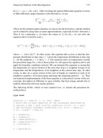
which errored signals may fall. An example of a 16-point constellation (4 bits/baud)
174 Connections, Codes, Signals, and Error Control
Figure A.6 Example of QAM to create a signal in which each symbol represents 2 bits.
is given in Figure A.7. In the upper diagram, the signal points are formed from a
minimum combination of two amplitudes and eight phase angles. The 16 signal
points are not uniformly distributed over signal space and the inner ring of eight
points has less signal space per point to cope with errors than the outer ring. To cor
-
rect this, a practical 16-point constellation is formed out of the combination of three
amplitudes and 12 phase angles shown in the lower diagram. The signal points are
distributed uniformly, and each has the same signal space as its neighbors.
The successful deployment of various flavors of digital subscriber lines depends
on the use of complex passband signal processing algorithms. Some of them are:
•
Pulse amplitude modulation: A popular modulation format uses trellis-coded
PAM with 3 bits per symbol and a 16-level constellation. The coding employs
twice as many signal points in the constellation as are needed to represent the
signal points. This redundancy is a form of forward error correction coding
and is used to reduce errors.
•
Carrierless amplitude and phase (CAP) modulation: A passband technology
based on QAM. With a 256-point constellation (i.e., 8 bits per symbol) and a
A.4 Signals 175
Signal point
0°
90°
180°
270°
360°
Concept
2 amplitudes
8 phase angles
Signal point
0°
90°
180°
270°
360°
Practical implementation
3 amplitudes
12 phase angles
Figure A.7 16-point signal constellations.
signaling rate of 1,088 kbaud, bit rates of 8.704 Mbps are achieved. CAP
employs trellis coding, Viterbi decoding, and Reed-Solomon forward error
correction. Viterbi decoding implements maximum likelihood decoding of
convolutional codes. Reed-Solomon codes employ groups of bits (known as
symbols). With k information symbols, r parity symbols, and code words of
length n = k + r, it is able to correct r/2 errors in a symbol.
•
Discrete multitone transmission (DMT): A passband technology, DMT oper
-
ates over a range of frequencies. The available frequency band is divided into
parallel channels (4.3125 kHz wide). Known as bins, they employ QAM with
a 4 kbaud symbol rate and up to 15 bits per symbol.
A.4.3.3 Spread Spectrum Modulation
Developed largely by the military as a means of hiding communications from adver
-
saries, spread spectrum signals are hard to intercept and almost impossible to jam.
Examples of their use are global positioning systems (GPSs), mobile telephones, per
-
sonal communication systems (PCSs), and very small aperture satellite systems
(VSATs).
Spread spectrum modulation is a technique in which the message-bearing modu-
lated signal is processed (i.e., modulated again) to occupy a much greater bandwidth
than the minimum required to transmit the information it carries.
The spectrum is spread in two ways:
•
Frequency hopping: The frequency of the carrier of the narrowband-
modulated message signal is caused to hop from one value to another in a
high-speed, pseudorandom manner across the spread spectrum.
•
Direct sequence: The narrowband-modulated message signal is modulated by
a high-speed pseudorandom sequence to produce a signal that extends across
the spread spectrum.
Because the spread spectrum signal has a lower power density (i.e., watts/hertz)
than the original signal, it creates little interference in other signals in the same fre
-
quency band.
To generate a direct sequence spread spectrum signal requires remodulating the
modulated message signal with a high-speed semirandom sequence of 1s and 0s.
Each element (1 or 0) is called a chip, the bit speed is known as the chipping rate, and
specific arrangements of 1s and 0s are a chipping code. If each user is assigned a
chipping code that is orthogonal (a mathematical term meaning that the integral of
the product of any two codes is zero) to others in use, each code stream can be distin
-
guished from the codes of other users. Thus, many users can communicate in the
same frequency space. This is known as CDMA. It is widely used in mobile tele
-
phone systems and PCSs.
Code division multiple access (CDMA) is a direct-sequence spread spectrum
technique in which all stations in the network transmit on the same carrier and use
the same chip rate to spread the signal spectrum over a wide frequency range. Each
station employs a code that is orthogonal to the codes used by others. Each receiver
sees the sum of the spread spectrum signals as uncorrelated noise. It can demodulate
a specific signal if it has knowledge of the spreading code and the carrier frequency.
176 Connections, Codes, Signals, and Error Control
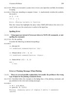
In the act of despreading the direct sequence spread spectrum signal, the
receiver spreads any interfering signals, thereby improving the signal-to-noise ratio.
Figure A.8 illustrates the relationships among: the original modulated message-
bearing signal; the direct sequence, spread spectrum, message-bearing signal; inter
-
fering noise; and the despread spread spectrum message-bearing signal at the
receiver. CDMA is a proven method of accommodating a large number of users in
limited spectrum space without mutual interference.
A.4.3.4 Orthogonal Frequency Division Multiplex (OFDM)
In some ways, OFDM is the antithesis of CDMA. Instead of spreading all users on a
single carrier using individual chipping codes, OFDM encodes a single user on
several carriers. It splits a wide frequency band into narrow channels and inverse
multiplexes a user’s data signal on the subcarriers occupying a channel. Inverse
A.4 Signals 177
Figure A.8 Illustrating the spreading of a message signal and the despreading of a spread spec
-
trum signal to yield the message signal and mitigate noise.
multiplexing is the action of splitting a higher-speed data stream into several
slower-speed streams that are carried on separate channels and recombined at the
terminating point. The channels are selected so that they overlap but the carriers do
not interfere with each other (i.e., they are orthogonal). OFDM uses the inverse fast
Fourier transform (IFFT) to create a composite signal from the inverse multiplexed
data signal. In signal analysis, the Fourier transform provides a means of transform
-
ing a time-varying signal into its equivalent frequency components. The fast Fourier
transform (FFT) is an implementation of the Fourier transform that produces a sig
-
nal waveform from a finite number of sine and cosine waves. The inverse Fourier
transform provides a means of transforming frequency components into an equiva
-
lent time-varying signal. At the receiver, the data stream is reconstructed using FFT.
A.5 Error Control
Noise corrupts the wanted signal and can produce errors in digital signals. Because
the noise signal is random, it may add to, or subtract from, the signal pulse train and
destroy the certainty of which level is present. Arguably, error control—the detec
-
tion and correction of errors—is the most important value-added service performed
by sending and receiving equipment.
Error control is a cooperative activity between a sender and receiver in which
the sender adds information to the code words and/or within the frame to assist the
receiver to determine whether an error has occurred. If it has, the sender and/or
receiver work together to correct it.
Figure A.9 shows the principle of error control. It is divided into error detection
and error correction.
A.5.1 Error Detection
Several techniques are available that detect the presence of an error or errors in the
frame received. They have different capabilities.
A.5.1.1 Vertical Redundancy Checking
One method of error detection adds parity bits to individual codes. I discussed this
technique with respect to ASCII code in Section A.2.
178 Connections, Codes, Signals, and Error Control
Figure A.9 Principle of error control.
A.5.1.2 Longitudinal Redundancy Checking
Bit-level error detection can be extended to check the entire sequence of bits between
the header and trailer in a frame. The sender calculates parity bits for the sequences
of bit positions #0, #1, , #7. They are placed in a byte located in the trailer. This
byte is known as the block check character (BCC). At the receiver, the same calcula
-
tions are run on the received frame. If the received BCC is the same as that calculated
by the receiver, the receiver has some assurance that the transmission does not con
-
tain errors. By using the combination of VRC and LRC, it is possible to locate the bit
position of single errors. Like VRC, LRC only detects odd numbers of errors.
A.5.1.3 Checksum
By treating the entire bit stream or segments of the bit stream as binary numbers,
error detection can be based on calculations. One process adds them together as
8-bit or 16-bit numbers and determines the ones complement of the result. The
sender attaches it to the bit stream it sends to the receiver. The receiver performs the
same addition and includes the ones complement. If the result is all 1s, the data
stream is likely to have been received without error.
A.5.1.4 Cyclic Redundancy Checking
In another process called cyclic redundancy checking (CRC), the sender calculates
an n-bit sequence. When attached to the k-bit sequence in the frame, it produces a k
+ n bit binary number that is exactly divisible by a given binary prime number called
the generating function. Known as the frame check sequence (FCS), the n-bit
sequence is placed in the trailer of the frame. Upon receipt, the receiver divides the k
+ n bit stream by the generating function used by the sender. If the remainder is zero,
the frame has been received without error. Figure A.10 shows the principle of cyclic
redundancy checking and lists some representative generating functions. CRC is a
powerful technique. It assures the receiver of detecting as few as 1 error in 10
14
bits.
A.5.2 Error Correction
Once detected, an error must be corrected. Two basic approaches to error correc
-
tion are:
•
Automatic-repeat-request (ARQ): Upon request from the receiver, the trans
-
mitter resends portions of the exchange in which errors have been detected.
•
Forward error correction (FEC): Employs special codes that allow the
receiver to detect and correct a limited number of errors without referring to
the transmitter.
A.5.2.1 ARQ Techniques
Three different procedures can be used to resend the portions of the exchange in
which errors are detected.
•
Stop-and-wait: The sender sends a frame and waits for acknowledgment from
the receiver. If no error is detected, the receiver sends a positive acknowledg
-
A.5 Error Control 179
ment (ACK). The sender responds with the next frame. If an error is detected,
the receiver returns a negative acknowledgment (NAK). The sender repeats the
frame.
•
Go-back-n: The sender sends a sequence of frames and receives an acknowl-
edgment from the receiver. On detecting an error, the receiver discards the cor-
rupted frame and ignores all further frames in the sequence. The receiver
notifies the sender of the number of the frame it expects to receive to replace
the first frame discarded. The sender begins resending the sequence starting
with that frame.
•
Selective-repeat: Used on duplex connections only. On the return channel, the
receiver returns negative acknowledgments for the individual frames found to
have errors. The sender repeats the frames for which NAKs are received.
A.5.2.2 Forward Error Correction
Forward error correction (FEC) requires the sender to add additional coding to seg
-
ments of the frame. Provided the number of errors is less than a value determined by
the coding, the receiver can detect and correct errors without reference to the sender.
In one technique (linear block coding), the sender adds check bits to information bits
in a known way building on the principle of parity checking. In another technique
(convolutional coding), the sender adds bits on the basis of logical operations per
-
formed on a moving string of information bits. In general, in an error environment
of less than one error in 10,000 information bits (1 in 10
4
), ARQ techniques are
superior to FEC. In an error environment of more than one in 1,000 (1 in 10
3
), FEC
must be employed.
Most of the early FEC codes assumed errors were randomly distributed. In
many instances, errors occur in bursts. They can be corrected to some extent by
interleaving the bits in a frame so that a burst of errors is spread out when the frame
is reassembled. In addition, complex block coding (e.g., Reed-Solomon codes) can
be used.
180 Connections, Codes, Signals, and Error Control
Figure A.10 Principle of cyclic redundancy check.
APPENDIX B
Frames and Headers
Because there are more details to the frames and headers than it is possible to
include in the chapter narratives, I have listed their fields and described their con
-
tents in this appendix. Each is entered in the order it is discussed. The entries are
divided by chapter. Capitals show the major divisions of each frame (namely, IEEE
802.3 MAC HEADER, IEEE 802.5 TRAILER, and so forth), small capitals are used
for field names (namely,
SOURCE PORT, DESTINATION PORT, LENGTH, and so forth),
and italics are used for subfields (namely, Precedence, Delay, and so forth).
B.1 Chapter 1: A TCP/IP World?
B.1.1 UDP Header
SOURCE PORT (2 bytes): Number of port in source from which message is sent.
Identifies the application layer protocol sending the UDP message. If no reply is
expected, the field may be set to 0×00–00.
DESTINATION PORT (2 bytes): Number of port in destination to which message
is sent. Identifies the destination application layer protocol receiving the UDP
message.
LENGTH (2 bytes): Length in bytes of the UDP Header + Data.
CHECKSUM (2 bytes): Provides integrity check of UDP message. Calculated over
UDP Pseudo Header + UDP Header + Payload.
B.1.2 TCP Header
SOURCE PORT (2 bytes): Number of port in source from which message is sent.
Identifies the application layer protocol sending the TCP segment.
DESTINATION PORT (2 bytes): Number of port in destination to which message
is sent. Indicates the destination application layer protocol receiving the TCP
segment.
SEQUENCE NUMBER (4 bytes): Number of outgoing segment’s first byte.
ACKNOWLEDGMENT NUMBER (4 bytes): Sequence number of the next
frame in the incoming byte stream that the receiver expects to receive. The
acknowledgment number provides a positive acknowledgment of all frames in
the incoming stream up to, but not including, the frame whose sequence
number is the acknowledgement number.
181
DATA OFFSET (4 bits): Number of 4-byte words in header. Used to indicate
where data begins. For the smallest header, the Data Offset field is set to 0x5
meaning the TCP segment data begins with the 20th byte offset from the
beginning of the TCP segment. For the maximum TCP header (i.e., with
Options and Padding), the Data Offset field is set to 0 × F, meaning the TCP
segment data begins with the 60th byte offset from the beginning of the TCP
segment.
RESERVED (6 bits): Set to 0. Reserved for future use.
FLAGS (6 bits): Individual bits are designated URG Urgent; ACK
Acknowledgment; PSH Push; RST Reset; SYN Synchronize; FIN Finish.
WINDOW (2 bytes): Number of bytes available in the receive buffer of the sender
of this segment.
CHECKSUM (2 bytes): Checks TCP segment (TCP Header + Payload). Calculated
over TCP pseudo header, TCP header, Payload, and any padding.
URGENT POINTER (2 bytes): Indicates the location of urgent data in the segment.
OPTIONS AND PADDING (n × 4 bytes): Variable size, but must be in 4-byte
increments. Used for negotiating maximum segment sizes, scaling window sizes,
performing selective acknowledgments, recording timestamps, and providing
padding to 4-byte boundaries. The presence of TCP options is indicated by a
Data Offset value greater than 5 (i.e., a TCP Header with a size greater than 20
bytes contains options).
B.1.3 IPv4 Header
VERSION (4 bits): Indicates version 4 in use (i.e., 0 × 4)
HEADER LENGTH (4 bits): Length of Header counted in 4-byte blocks. Used to
find beginning of payload.
TYPE OF SERVICE (1 byte): Usually set to 0×00. Indicates the quality of service
with which the datagram is to be delivered.
Precedence: A 3-bit subfield used to indicate the importance of the datagram;
Delay: A flag set to 0 for normal delay or to 1 for low delay;
Throughput: A flag set to 0 for normal throughput or to 1 for high
throughput;
Reliability: A flag set to 0 for normal reliability or to 1 for high reliability;
Cost: A flag set to 0 for normal cost or to 1 for low cost;
Reserved: The last bit is reserved for future use. It is set to 0.
TOTAL LENGTH (2 bytes): Length of the datagram (header + payload) in bytes.
IDENTIFIER (2 bytes): Number that identifies a specific packet sent between a
specific source and specific destination
FLAGS (3 bits): Contains flag to indicate whether datagram can be fragmented
and another flag to indicate whether more fragments follow.
FRAGMENT OFFSET (13 bits): Indicates where this fragment belongs relative to
the original datagram.
182 Frames and Headers
TIME TO LIVE (1 byte): Indicates number of links this datagram can travel before
it is destroyed. Each node decrements the TTL count by one when forwarding
the datagram. Prevents defective datagrams from circulating forever.
PROTOCOL (1 byte): Indicates the upper layer protocol contained within the IP
payload. Common values are ICMP, 0×01; IGMP, 0×02; TCP, 0×06; and UDP,
0×11.
HEADER CHECKSUM (2 bytes): Checks IP header only; payload is not included.
SOURCE IP ADDRESS (4 bytes): Contains the IP address of the source host (or
Network Address Translator).
DESTINATION ADDRESS (4 bytes): Contains the IP address of the destination
host (or Network Address Translator).
OPTIONS AND PADDING (n×4 bytes): Options can be added to the IP header. It may
have to be padded to bring the length to a multiple of 4 bytes. Some options are:
Record Route: Used to trace a route through an IP internetwork;
Loose Source Routing: Used to route a datagram along a specified path with
alternate routes;
Strict Source Routing: Used to route a datagram along a specific path without
alternate routes;
Internet Timestamp: Used to record a series of timestamps (e.g., time at each
hop).
B.1.4 IPv6 Header
VERSION (4 bits): Indicates version 6 in use, (i.e., 0×6).
TRAFFIC CLASS (8 bits): Identifies traffic priority needed to meet QoS objectives.
FLOW LABEL (20 bits): Indicates the length of the remainder of the packet, in
bytes.
PAYLOAD LENGTH (2 bytes): Indicates the length of the remainder of the packet,
in bytes.
NEXT HEADER (1 byte): Identifies header immediately following this header.
Same as protocol field in IPv4. Common values are ICMP, 0×01; IGMP, 0×02;
TCP, 0×06; and UDP, 0×11.
HOP LIMIT (8 bits): Number of links to go before packet is discarded.
SOURCE ADDRESS (16 bytes): Unicast address of sending node.
DESTINATION ADDRESS (16 bytes): Address of final destination or NAT.
EXTENSION HEADERS (n×8 bytes): Up to eight extension headers: Hop-by-Hop;
Destinations; Routing; Fragment; Authentication; Encapsulating Security
Payload; Destination; TCP Header and Data.
B.1.5 ICMP Frame
NETWORK INTERFACE HEADER
IP HEADER
B.1 Chapter 1: A TCP/IP World? 183
ICMP HEADER
TYPE (1 byte): 0, Echo Reply; 3, Destination Unreachable; 4, Source Quench; 5,
Redirect; 8, Echo Request; 9, Router Advertisement; 10, Router Selection; 11,
Time Exceeded; 12, Parameter Problem.
CODE (1 byte): Indicates a specific ICMP message within the message type in the
type field. If there is only one ICMP message within an ICMP message type, it is
set to 0.
CHECKSUM (2 bytes): Checks ICMP header only.
PAYLOAD
TYPE SPECIFIC DATA (n bytes): Variable to accommodate data for each type of
message.
NETWORK INTERFACE TRAILER
B.1.6 Echo Request and Reply Messages
TYPE (1 byte): Set to 8 for Echo Request and 0 for Echo Reply.
CODE (1 byte): Set to 0 for both messages. There are no specific ICMP messages
within the message type.
CHECKSUM (2 bytes): 16-bit sum that checks ICMP header and ICMP message
data.
IDENTIFIER (2 bytes): Number generated by sender used to match Echo Reply
with its Echo Request.
SEQUENCE NUMBER (2 bytes): Contains additional number used to match the
Echo Reply with its Echo Request.
OPTIONAL DATA (n bytes): Variable; explanatory data can be added to the
frame.
B.1.7 Destination Unreachable Message
TYPE (1 byte): Set to 3
CODE (1 byte): Some values are: 1, Host unreachable; 2, Protocol unreachable; 4,
Fragmentation needed; 5, Source Route failed; 7, Destination Host unknown; 9,
Communication with Destination Network administratively prohibited.
CHECKSUM (2 bytes): 16-bit sum that checks ICMP header and message data.
UNUSED (4 bytes): For future use.
DATA (variable): IP header and first 8 bytes of datagram payload.
B.1.8 ARP Request and Reply Messages
HARDWARE TYPE (1 byte): Length in bytes of hardware address in Sender’s
Hardware Address and Target Hardware Address fields.
PROTOCOL ADDRESS LENGTH (1 byte): Length in bytes of protocol address in
Sender’s Protocol Address and Target Protocol Address fields.
184 Frames and Headers
OPERATION (2 bytes): Indicates type of ARP frame: 1, ARP Request; 2, ARP
Reply; 8, Inverse ARP Request; 9, Inverse ARP Reply.
SENDER HARDWARE ADDRESS (6 bytes): Contains hardware address of node
sending ARP frame.
SENDER PROTOCOL ADDRESS (6 bytes): For IP, SPA field is 4 bytes. Contains the
IP address of the node sending the ARP frame.
TARGET HARDWARE ADDRESS (6 bytes): Set to 0×00–00–00–00–00–00 for ARP
Request frames and to hardware address of ARP requester for ARP Reply
frames.
TARGET PROTOCOL ADDRESS (6 bytes): For IP, TPA field is 4 bytes. In ARP
Request frame it is set to IP address being resolved. In ARP Reply frame it is set
to address of IP requester.
B.2 Chapter 3: Local Area Networks
B.2.1 Classic Ethernet Frame
HEADER
PREAMBLE (8 bytes): 0×AA-AA-AA-AA-AA-AA-AA-AB
DESTINATION ADDRESS (6 bytes): If address is unicast, contains the hardware
address of a specific station. If address is multicast, carries a code that identifies a
group of stations. If address is broadcast, contains code 0×FF-FF-FF-FF-FF-FF.
SOURCE ADDRESS (6 bytes): Unicast address of station where frame originated.
ETHERTYPE (2 bytes): Code indicating upper layer protocol contained in frame.
For IP datagram set to 0×08-00; for ARP set to 0×08-06.
PAYLOAD
IP DATAGRAM (46 to 1,500 bytes): Contains Internet layer header, transport
layer header, and application PDU.
TRAILER
FRAME CHECK SEQUENCE (4 bytes): Remainder from dividing the data stream
between the Preamble and FCS by a 33-bit prime number.
B.2.2 IEEE 802.3 Ethernet Frame
IEEE 802.3 MAC HEADER
PREAMBLE (7 bytes): 0×AA-AA-AA-AA-AA-AA-AA
START DELIMITER (1 byte): 0AB
DESTINATION ADDRESS (2 or 6 bytes): If address is unicast, contains
the hardware address of a specific station. If address is multicast, carries a code
that identifies a group of stations. If address is broadcast, contains code
0×FF-FF-FF-FF-FF-FF. Bits 1 and 2 of byte 1 are used to identify Universal/
Local and Individual/Group addresses.
B.2 Chapter 3: Local Area Networks 185
SOURCE ADDRESS (2 or 6 bytes): Unicast address of station whence frame
originated. Bit 1 of byte 1 is used to indicate whether Token Ring MAC-level
routing information is present.
LENGTH (2 bytes): Number of bytes from first byte of 802.2 LLC Header to last
byte of Payload. Number is 1,500 (0×05-DC). Distinguishes MAC Header from
Classic Ethernet header.
IEEE 802.2 LLC HEADER
DESTINATION SAP (1 byte): Identifies point to which payload is delivered. For IP,
DSAP = 0×06. Set to 0×AA when combined with SNAP header.
SOURCE SAP (1 byte): Identifies point from which payload originated. For IP,
SSAP = 0×06. Set to 0×AA when combined with SNAP header.
CONTROL (1 or 2 bytes): Type 1: If encapsulated data is an IP datagram or ARP
message, Control field is 1 byte and is set to 0×03 [Unnumbered Information
(UI) frame]. Type 2: If encapsulated data is part of a connection-oriented
session, the Control field is 2 bytes. IP datagrams and ARP messages are always
sent as Type 1.
IEEE 802.3 SNAP HEADER
ORGANIZATION CODE (3 bytes): Identifies organization that maintains meaning
of EtherType field. For IP datagrams and ARP messages, set to 0×00–00–00.
ETHERTYPE (2 bytes): Identifies upper layer protocol in frame. For IP datagrams,
value is 0×08–00. For ARP messages, value is 0×08–06.
PAYLOAD
IP DATAGRAM (38 to 1,492 bytes): 8 bytes less than Classic Ethernet because of
extra bytes in headers.
IEEE 802.3 TRAILER
FRAME CHECK SEQUENCE (4 bytes): Remainder from dividing the data stream
between the Preamble and FCS by a 33-bit prime number.
B.2.3 IEEE 802.5 Token Ring Frame
IEEE 802.5 HEADER
STARTING DELIMITER (1 byte): 0×JK. Contains two nondata symbols called J
and K symbols. The J symbol is an encoding violation of 1; the K symbol is an
encoding violation of 0. The Starting Delimiter provides a synchronizing signal.
ACCESS CONTROL (1 byte):
Priority bits: 3 bits (7 levels) that establish the priority the receiving station
must have in order to seize the token and send a frame.
Token bit: Set to 0, the frame is a token. Set to 1, the frame is in use.
Monitor bit: Set to 1, the frame has passed the monitor station. If it appears a
second time at the monitor, the frame is destroyed, and the monitor station
generates an empty token.
Reservation bits: 3 bits that record the priority of a station upstream that
wants the token. If the station currently handling the frame has something to
186 Frames and Headers
send and its allocated priority is greater than the level to which the present
reservation bits are set, it upgrades the reservation level to equal its allocated
priority. The reservation bits become the priority bits when the station that is
currently using it releases the token.
FRAME CONTROL (1 byte): 2 bits are reserved for future use.
Frame Type: 2 bits indicating the frame is a Token Ring MAC management
frame, or a Token Ring LLC frame.
MAC Management Frame Type: 4 bits indicating the type of MAC
management frame.
DESTINATION ADDRESS (6 bytes): The address of the destination station. It may
be: a universal or locally administered unicast address; the universal broadcast
address 0×FF–FF–FF–FF–FF–FF; the Token Ring broadcast address
0×C0–00–FF–FF–FF–FF; a multicast address; or a Token Ring functional
address used by Token Ring MAC management frames. A frame using the
Token Ring broadcast address remains on a single ring. Token Ring
source-route bridges do not forward it.
SOURCE ADDRESS (6 bytes): Unicast address of station where frame originated.
IEEE 802.2 LLC HEADER
DESTINATION SAP (1 byte): For IP, set to 0×AA.
SOURCE SAP (1 byte): For IP, set to 0×AA.
CONTROL (1 byte): For IP, set to 0×03 [Unnumbered Information (UI) frame].
IEEE 802.3 SNAP HEADER
ORGANIZATION CODE (3 bytes): For IP datagrams and ARP messages, the
Organization code is set to 0×00–00–00.
ETHERTYPE (2 bytes): For IP datagrams, value is 0×08–00. For ARP messages,
value is 0×08–06.
PAYLOAD
IP DATAGRAM: No minimum size. Maximum size depends on the bit rate and
the token holding time. For a token holding time of 10 ms, the maximum sizes
for IP datagrams are 4,464 bytes at 4 Mbps and 17,914 bytes for 16 Mbps.
IEEE 802.5 TRAILER
FRAME CHECK SEQUENCE (4 bytes): Remainder from dividing the data stream
between the access control byte and FCS by a 33-bit prime number.
ENDING DELIMITER (1 byte): Identifies the end of the frame. Contains J and K
nondata symbols. Also contains:
Intermediate frame indicator bit: 1 bit used to indicate whether this is the last
frame of a sequence (0), or more frames are to follow (1);
Error detected indicator bit: 1 bit used to indicate whether the frame failed
FCS checking. The FCS is checked at each node on the ring. If the FCS fails
at any node, the error bit is set to 1. The receiving node does not copy the
frame.
FRAME STATUS (1 byte):
B.2 Chapter 3: Local Area Networks 187
Address recognized indicator bit (duplicate copies): 1 bit set by the
destination node to indicate that the address was recognized.
Frame copied indicator bit (duplicate copies): 1 bit set by the destination node
to indicate the frame was copied successfully. Because they are not checked by
FCS, the bits are duplicated.
B.2.4 FDDI Frame
FDDI HEADER
PREAMBLE (2 bytes): Provides receiver synchronization. 0×AA-AA.
STARTING DELIMITER (1 byte): 0×JK. Contains two nondata symbols called J
and K symbols. The J symbol is an encoding violation of 1; the K symbol is an
encoding violation of 0.
FRAME CONTROL (1 byte):
Class:1 bit denoting synchronous frame (1), or asynchronous frame (0).
Address: 1 bit denoting source and destination addresses are 2 bytes (0), or 6
bytes (1).
Frame Type: 6 bits indicating the type of frame (i.e., token, MAC frame, LLC
frame).
DESTINATION ADDRESS (2 or 6 bytes): Indicates the address of the destination
station. 2 byte addressing is not used with IP/ARP. For interoperability, made
the same as Ethernet destination addresses. Bits 1 and 2 of byte 1 are used to
identify universal or local addresses, and individual or group addresses.
SOURCE ADDRESS (2 or 6 bytes): Unicast address of station whence frame
originated. 2 byte addressing is not used with IP/ARP. Bit 1 of byte 1 identifies
whether Token-Ring MAC level routing information is present.
IEEE 802.2 LLC HEADER
DESTINATION SAP (1 byte): Identifies point to which payload is delivered. For IP,
DSAP = 0×06. Set to 0×AA when combined with SNAP.
SOURCE SAP (1 byte): Identifies point from which payload is sent. For IP, SSAP =
0×06. Set to 0×AA when combined with SNAP.
CONTROL (1 byte): For IP, set to 003 [Unnumbered Information (UI) frame].
IEEE 802.3 SNAP HEADER
ORGANIZATION CODE (3 bytes): For IP datagrams and ARP messages, the
organization code is set to 0×00–00–00.
ETHERTYPE (2 bytes): For IP datagrams, value is 0×08–00. For ARP messages,
value is 0×08–06.
PAYLOAD
IP DATAGRAM (up to 4,352 bytes): No minimum size. Maximum frame size
from start of Preamble through Frame Status is 4,500 bytes. FDDI header and
trailer are 22 bytes. LLC header is 3 bytes. SNAP header is 5 bytes. 117 bytes are
reserved for future uses.
FDDI TRAILER
188 Frames and Headers
FRAME CHECK SEQUENCE (4 bytes): Remainder from dividing the data stream
between the access control byte and FCS by a 33-bit prime number.
ENDING DELIMITER (1 byte): Identifies the end of the frame. Contains J and K
nondata symbols. Also contains:
Intermediate frame indicator bit, 1 bit used to indicate whether this is the last
frame of a sequence (0), or more frames are to follow (1);
Error detected indicator bit, 1 bit used to indicate whether the frame failed
FCS checking. (The FCS is checked at each node on the ring. If the FCS fails at
any node, the error bit is set to 1. The receiving node does not copy the
frame.)
FRAME STATUS (1 byte):
Address recognized indicator bit (duplicate copies): 2×1 bit set by the
destination node to indicate that the address was recognized.
Frame copied indicator bit (duplicate copies): 2×1 bit set by the destination
node to indicate the frame was copied successfully. Because they are not
checked by FCS, the bits are duplicated.
B.3 Chapter 4: Wide Area Networks
B.3.1 Point-to-Point Protocol (PPP) Frame
HDLC HEADER
FLAG (1 byte): 0×7E
ADDRESS (1 byte): Because the connection is point-to-point, set to 0×FF. May be
omitted.
CONTROL (1 byte): Set to 0×30 [i.e., Unumbered Information (UI) frame with
Poll/Final bit set to 0]. May be omitted.
PROTOCOL (2 bytes): For an IP datagram, set to 0×00–21.
PAYLOAD
IP DATAGRAM ( 1,500 bytes)
HDLC TRAILER
FRAME CHECK SEQUENCE (2 bytes): Remainder from dividing the data stream
between the Begin Flag and FCS by a 17-bit prime number.
FLAG (1 byte): 0×7E
B.3.2 X.25 Data Frame
LINK ACCESS PROTOCOL – BALANCED (LAPB) HEADER
FLAG (1 byte): 0×7E
ADDRESS (1 byte): Indicate command or response frame.
CONTROL (1 byte): Provides further information on command and response
frames and indicates frame format and function.
B.3 Chapter 4: Wide Area Networks 189
PACKET LAYER PROTOCOL (PLP) HEADER
GENERAL FORMAT INDICATOR (4 bits): Identifies the payload as user’s data or
an X.25 message. Specifies the packet numbering cycle is 7 or 127. Specifies
whether delivery confirmation is required.
LOGICAL GROUP/ CHANNEL NUMBER (4 + 8 bits): Identifies virtual circuit over
which frame will travel between DTE and DCE.
SEQUENCING (1 or 2 bytes): Provides number of this frame [N(S)], number of
frame receiver expects [N(R)], and fragmentation information for user’s
segments.
PAYLOAD
NETWORK LAYER PROTOCOL IDENTIFIER (NLPID) (1 byte): For an IP datagram
set to 0×CC. For a single protocol virtual circuit (e.g., only IP), NLPID is
omitted.
IP DATAGRAM (≤ 4,096 bytes)
LAPB TRAILER
FRAME CHECK SEQUENCE (2 bytes); Remainder from dividing the data stream
between the Begin Flag and FCS by a 17-bit prime number.
FLAG (1 byte): 0×7E
B.3.3 ATM Cell Structure
HEADER
GENERIC FLOW CONTROL (4 bits): User-node interface (UNI) only. Intended to
support local connections. Little used.
VIRTUAL PATH IDENTIFIER (VPI) (UNI 1 byte, NNI 12 bits): Different for UNI
and node-network interface (NNI). With VCI points to the location in switch
tables that contains the actual route.
VIRTUAL CHANNEL IDENTIFIER (VCI) (2 bytes): With VPI points to the location in
switch tables that contains the actual route.
PAYLOAD TYPE IDENTIFIER (PTI) (3 bits): Identifies payload as user payload or
network management payload.
CELL LOSS PRIORITY (CPI) (1 bit): Guides cell discard in event of congestion. 1
signifies lower priority cell that should be discarded first. 0 signifies higher
priority cell.
HEADER ERROR CONTROL (HEC) (1 byte): CRC computed over cell header.
PAYLOAD
SEGMENT (48 bytes): First 4 bytes may be used for AAL control information.
B.3.4 AAL5 Frame Containing IP Datagram
LLC HEADER: standard
SNAP HEADER: standard
PAYLOAD
190 Frames and Headers
IP DATAGRAM (38 to 1,492 bytes)
PAD (≤47 bytes)
AAL5 TRAILER
USER-TO-USER INDICATOR (1 byte): Transfers information between AAL users
(not defined).
COMMON PART INDICATOR (1 byte): Aligns the AAL5 trailer on a 64-bit
boundary.
LENGTH OF PAYLOAD (2 bytes): Length in bytes of the Payload so receiver can
discard Pad.
FRAME CHECK SEQUENCE (4 bytes): Remainder from dividing the data stream
formed by payload and trailer by a 33-bit prime number.
B.3.5 Frame Relay Frame with 2-Byte Addresses
FRAME RELAY HEADER
FLAG (1 byte): 0×7E
ADDRESS (2 bytes):
Data link connection identifier (DLCI): The first 6 bits of the first byte and
the first 4 bits of the second byte comprise the 10-bit DLCI. It identifies the
virtual circuit over which the frame relay (FR) frame is transported. The
DLCI is only locally significant. Each FR switch changes the DLCI value as it
forwards the FR frame.
Command/Response (C/R): The seventh bit in the first byte of the address
field is the C/R bit. It is not used and is set to 0.
Extended address (EA): The last bit in each byte of the address field is the EA
bit. If it is set to 1, the current byte is the last byte in the address field. Set to 0,
there is at least one more address byte to follow.
Forward explicit congestion notification (FECN): The fifth bit in the second
byte of the address field is the FECN bit. It is used to inform the destination
node that congestion exists in the path from source to destination. The FECN
bit is set to 1 by any FR node in the forward path that is becoming congested.
When the destination node receives a frame with FECN set to 1, the
information is passed to upper layer protocols that may initiate flow control
procedures (receive side).
Backward explicit congestion notification (BECN): The sixth bit in the
second byte of the address field is the BECN bit. It is used to inform the
destination node that congestion exists in the path from destination to
source. The BECN bit is set to 1 by any FR node that is becoming congested
in the reverse path. When the destination node receives a frame with BECN
set to 1, the information is passed to upper layer protocols that may initiate
flow control procedures (send side).
Discard eligibility (DE): The seventh bit in the second byte of the address
field is the DE bit. The first FR node sets the DE bit to 1 when the sender
exceeds the committed information rate (CIR). Frames with DE = 1 are
discarded first during periods of congestion.
B.3 Chapter 4: Wide Area Networks 191
CONTROL (1 byte): Set to 0×30
PAYLOAD
NETWORK LAYER PROTOCOL IDENTIFIER (1 byte): For an IP datagram set to
0×CC. For a single protocol virtual circuit, NLPID is omitted.
IP DATAGRAM (262 to 1,600 bytes)
FRAME RELAY TRAILER
FRAME CHECK SEQUENCE (2 bytes): Remainder from dividing the datastream
between the Begin Flag and FCS by a 17-bit prime number.
FLAG (1 byte): 0×7E
B.4 Chapter 5: Connecting Networks Together
B.4.1 Source Routing Added to Token Ring Frame
IEEE 802.5 HEADER
STARTING DELIMITER: standard
ACCESS CONTROL: standard
FRAME CONTROL: standard
DESTINATION ADDRESS: standard
SOURCE ADDRESS (6 bytes): Bit 1: Set to 1, Source routed.
ROUTING CONTROL (2 bytes):
Routing Type (3 bits): 0xx, specifically routed frame; 11x, Spanning Tree
Explorer; 10x, All Routes Explorer.
Length (5 bits): number of bytes in Routing Control and Route Descriptors.
Direction (1 bit): 0, read Route Descriptors left to right; 1, read Route
Descriptors right to left.
Largest Frame (6 bits): indicates largest data payload field supported by
route.
Reserved: 1 bit.
Route Descriptors (≤28 bytes): Route Descriptor #1 (2 bytes), Ring number
(12 bits), Bridge number (4 bits). Route Descriptor #14 (2 bytes), Ring
number (12 bits), Bridge number (4 bits).
IEEE 802.2 LLC HEADER: standard
PAYLOAD: IP Datagram
IEEE 802.5 TRAILER: standard
B.4.2 Tag for IEEE 802.3 (Ethernet) Frame Encapsulating an IP Datagram
IEEE 802.3 MAC HEADER: standard
IEEE 802.2 LLC HEADER: standard
IEEE 802.3 SNAP HEADER
192 Frames and Headers
ORGANIZATION CODE: Standard
ETHERTYPE (2 bytes): 0×81-00
TAG CONTROL INFORMATION FIELD (2 bytes):
Byte 1: bits 0 through 3, VLAN Identifier; bit 4, CFI, canonical format
indicator; bits 5, 6, 7, priority information
Byte 2: bits 0 through 7, VLAN Identifier
PAYLOAD
IEEE 802.3 TRAILER: standard
B.4.3 IEEE 802.3 (Ethernet) Frame with Embedded Routing Information
IEEE 802.3 MAC HEADER: standard
IEEE 802.2 LLC HEADER: standard
IEEE 802.3 SNAP HEADER
ORGANIZATION CODE: Standard
ETHERTYPE: Standard
TAG CONTROL INFORMATION FIELD: Standard
ROUTING CONTROL (2 bytes):
Routing Type (3 bits): 00×, specifically routed frame; 01×, transparently
bridged frame; 10×, All Routes Explorer; 11x, Spanning Tree Explorer
frame.
Length (5 bits): number of bytes in Route Descriptor field.
Direction (1 bit): 0, read Route Descriptors left to right; 1, read Route
Descriptors right to left.
Largest Frame (6 bits): indicates largest data payload field supported by
route.
Noncanonical Format Indicator (1 bit): 0, Big Endian format; 1, Little
Endian format
ROUTE DESCRIPTORS (≤ 28 bytes): Route Descriptor #1 (2 bytes): LAN
Identifier (12 bits), Bridge number (4 bits). Route Descriptor #14 (2 bytes):
LAN Identifier (12 bits), Bridge number (4 bits).
PAYLOAD: IP Datagram
IEEE 802.3 TRAILER: standard
B.5 Chapter 6: Protecting Enterprise Catenets
B.5.1 Authentication Header Fields in Datagrams in Figure 6.6
AUTHENTICATION HEADER
NEXT HEADER (1 byte): Identity of Header following AH. UDP = 0×11; TCP =
0×06.
LENGTH (2 bytes): Length of Authentication Header.
B.5 Chapter 6: Protecting Enterprise Catenets 193
RESERVED (2 bytes): Set to 0×00-00, not allocated.
SECURITY PARAMETERS INDEX (4 bytes): In combination with destination
address, identifies Security Association to be used.
SEQUENCE NUMBER (4 bytes): Datagram identifier. Begins at 0 when new
Security Association is invoked. Counts by 1s. Prevents repetition of datagram.
AUTHENTICATION DATA (variable): Datagram identifier. Begins at 0 when new
SA invoked. Counts by 1s. Prevents repetition of datagram.
B.5.2 Encapsulating Security Header and Trailer
IP HEADER: Protocol field is set to 0×32 to indicate ESP.
ENCAPSULATING SECURITY PAYLOAD (ESP) HEADER
SECURITY PARAMETERS INDEX (4 bytes): In combination with destination
address, identifies security association to be used.
AUTHENTICATION DATA (variable): Hash integrity check from ESP header to
ESP trailer. All mutable fields are set to 0s, and all immutable fields retain their
values. The authentication data field is set to 0 during the calculation.
TCP HEADER: Authenticated, Encrypted.
PAYLOAD: Authenticated, Encrypted.
ESP TRAILER
PADDING (variable): Up to 255 bytes of padding.
PADDING LENGTH (1 byte): Number of bytes in padding field.
NEXT HEADER (1 byte): Identity of next header.
ESP AUTHENTICATION DATA (variable):
B.6 Chapter 7: Transmission Facilities
B.6.1 IEEE 802.11 Frame Containing IEEE 802.3 Payload
IEEE 802.11 HEADER
FRAME CONTROL (2 bytes):
Bits 0 and 1: indicate which version of 802.11 is in use. Set to 00 since only
one version exists.
Bits 2 and 3: identify type of frame. Set to 00 for management frames; 01
control frames; 10 data frames.
Bits 4 through 7: identify subtype of frame (e.g., set to 1011 for RTS and
1100 for CTS control frames).
Bit 8: ToDS bit. Set to 1 for data frames transmitted from movable station to
AP.
Bit 9: From DS bit. Set to 1 for data frames transmitted from AP to movable
station.
Bit 10: More fragments bit. Set to 1 if fragments following. Set to 0 for final
segment.
194 Frames and Headers
Bit 11: Retry bit. Set to 1 for retransmitted frames.
Bit 12: Power management bit. Set to 1 if movable station will enter power
saving mode after this frame.
Bit 13: More data bit. Set to 1 by AP to alert movable station in power saving
mode that AP has at least one frame for delivery.
Bit 14: WEP bit. Set to 1 when frame has been encrypted by Wired Equivalent
Privacy (WEP) to protect data and authenticate sender.
Bit 15: Order bit. Set to 1 when frames must be delivered in sequence.
DURATION/ID (2 bytes): When bit 15 is set to 0, bits 0 through 14 (NAV)
indicate the time (in microseconds) the medium is expected to remain busy for
the transmission in progress. When bit 15 is set to 1, and bits 0 through 14 are
set to 0, indicates a contention-free period of 32,768 microseconds. When bits
14 and 15 are set to 0, indicates a station has changed from power-saving mode
to powered mode.
ADDRESS 1 (6 bytes): 48-bit MAC address of destination (from 802.3 frame).
ADDRESS 2 (6 bytes): 48-bit MAC address of source (from 802.3 frame).
ADDRESS 3 (6 bytes): 48-bit MAC address of AP/BSS hosting movable station.
SEQUENCE CONTROL (2 bytes): Used in reconstructing frames and discarding
duplicate frames.
Fragment number: Bits 0 thru 3
Sequence number: Bits 4 thru 15, all fragments of a fragmented frame carry the
same sequence number.
ADDRESS 4 (6 bytes): 48-bit MAC address for future use.
PAYLOAD Consists of 802.3 LLC and SNAP header and IP packet.
TRAILER
FRAME CHECK SEQUENCE (4 bytes): Checks entire IEEE 802.11 frame.
B.6 Chapter 7: Transmission Facilities 195
.
List of Acronyms and Abbreviations
4B/5B 4 binary/5 binary
8B/10B 8 binary/10 binary
AAL ATM adaptation layer
ABM asynchronous balanced mode
ABR available bit rate
ACELP Algebraic-Code-Excited-Linear-Prediction
ACK acknowledge
ADM add/drop multiplexer
ADPCM adaptive differential PCM
ADSL asymmetrical digital subscriber line
AMI alternate mark inversion signal format
APDU application protocol data unit
ARP Address Resolution Protocol
ARPA Advanced Research Projects Agency
ARPAnet ARPA network
ARQ await receiver request
ASCII American Standard Code for Information Interchange
ASK amplitude shift keying
ASP adjunct service point
ATM asynchronous transfer mode
B8ZS bipolar with 8 zeros substitution
BCC block check character
B-ISDN broadband ISDN
BISYNC Binary Synchronous Data Link Control Protocol
BS bursty second
BSS basic service set
BT bridged tap
CA certificate authority
CAP carrierless amplitude and phase
197
CBR constant bit rate
CDMA code division multiple access
CELP Code-Excited-Linear-Prediction
CI congestion indicator
CIDR classless interdomain routing
CIR committed information rate
CLASS custom local-area signaling services
CLEC competitive local exchange carrier
CLP cell loss priority
CLR cell loss rate
CMR cell misinsertion rate
CMTS cable modem termination system
CO central office
CORE Council of Registrars
COT central office terminal
CRC cyclic redundancy check
CRS cell relay service
CS convergence sublayer
CSA carrier serving area
CSA-CELP Conjugate-Structure Algebraic-Code-Excited-Linear-Prediction
CSN current sequence number
CSMA/CA carrier sense multiple access with collision avoidance
CSMA/CD carrier sense multiple access with collision detection
CSU customer service unit; channel service unit
CTS clear to send
dB decibel
DCC digital cross-connect
DCE data circuit equipment
DCF distributed coordination function
DHCP Dynamic Host Configuration Protocol
DiffServ differentiated services
DIFS distributed coordination function interframe space
DLCI data link connection identifier
DLE data link escape
DNHR dynamic nonhierarchical routing
DMT discrete multitone transmission
198 List of Acronyms and Abbreviations