all in one cisco ccie lab study guide second edition phần 2 ppsx
Bạn đang xem bản rút gọn của tài liệu. Xem và tải ngay bản đầy đủ của tài liệu tại đây (523.58 KB, 89 trang )
!
enable password cisco
!
username RouterB password 7 070C285F4D06
isdn switch−type basic−ni1 ← Set D channel call control
!
interface BRI0/0
no ip address
encapsulation ppp
isdn spid1 5101 8995101 ← Set SPIDs for both B channels
isdn spid2 5102 8995102
dialer pool−member 1 ← This interface will be part of dialer pool #1
no fair−queue
ppp authentication chap
ppp multilink ← Request a PPP multilink session
!
interface Dialer0
ip address 196.1.1.1 255.255.255.0
encapsulation ppp
dialer remote−name RouterB ← Hostname of far end router
dialer idle−timeout 90 ← Disconnect the call 90 seconds after the last
interesting packet is received
dialer string 8995201 ← Define number to dial to reach far end
dialer load−threshold 1 ← Define threshold for adding additional B channels
dialer pool 1 ← This is dialer pool #1
dialer−group 1 ← Associate this interface with dialer−list 1
!
no ip classless
ip route 196.1.1.2 255.255.255.255 Dialer0
dialer−list 1 protocol ip permit ← Define interesting traffic
!
line con 0
password cisco
login
line aux 0
line vty 0 4
password cisco
login
!
end
RouterB
RouterB#show run
Building configuration...
Current configuration:
!
version 11.2
service timestamps debug datetime localtime
no service udp−small−servers
no service tcp−small−servers
!
hostname RouterB
!
enable password cisco
!
username RouterA password 7 094F471A1A0A
isdn switch−type basic−ni1 ← Set the D channel call control
!
interface Serial0/0
ip address 193.1.1.2 255.255.255.0
encapsulation ppp
!
interface BRI0/0
ip address 196.1.1.2 255.255.255.0
encapsulation ppp
62
isdn spid1 5201 8995201 ← Set the SPID for both B channels
isdn spid2 5202 8995202
dialer idle−timeout 90 ← Define the interesting traffic timeout
dialer map ip 196.1.1.1 name RouterA ← Define a next hop address
dialer−group 1 ← Associate the interface with dialer−list 1
no fair−queue
ppp authentication chap
ppp multilink
!
no ip classless
dialer−list 1 protocol ip permit ← Define interesting traffic
!
line con 0
line aux 0
line vty 0 4
password cisco
login
!
end
Monitoring and Testing the Configuration
Let's start by connecting to RouterB and verifying that the ISDN circuit is up and active. Type the show isdn
status command to view the status of the BRI circuit on RouterB. We see that the SPID for both B channels
has been sent to the ISDN switch and is valid.
RouterB#show isdn status
The current ISDN Switchtype = basic−ni1
ISDN BRI0/0 interface
Layer 1 Status:
ACTIVE
Layer 2 Status:
TEI = 64, State = MULTIPLE_FRAME_ESTABLISHED
TEI = 65, State = MULTIPLE_FRAME_ESTABLISHED
Spid Status:
TEI 64, ces = 1, state = 5(init)
spid1 configured, spid1 sent, spid1 valid ← B channel #1
Endpoint ID Info: epsf = 0, usid = 70, tid = 1
TEI 65, ces = 2, state = 5(init)
spid2 configured, spid2 sent, spid2 valid ← B channel #2
Endpoint ID Info: epsf = 0, usid = 70, tid = 2
Layer 3 Status:
0 Active Layer 3 Call(s)
Activated dsl 0 CCBs = 1
CCB:callid=0, callref=0, sapi=0, ces=1, B−chan=0
Number of active calls = 0
Number of available B−channels = 2
Total Allocated ISDN CCBs = 1
Let's verify the status of the bri interface and make sure that the D channel is active between RouterB and the
ISDN switch. Type show interface bri 0/0 to view the status of the D channel. The up/up (spoofing) state
indicates that the D channel is up and active.
RouterB#show interface bri 0/0
BRI0/0 is up, line protocol is up (spoofing) ← Active D channel
Hardware is QUICC BRI with U interface
Internet address is 196.1.1.2/24
MTU 1500 bytes, BW 64 Kbit, DLY 20000 usec, rely 255/255, load 1/255
Encapsulation PPP, loopback not set
.
.
Now let's connect to RouterA and verify that the BRI interface is ready to place a call. Type the show isdn
status command to view the status of the BRI interface. We see that a SPID for B channel #1 and B channel
63
#2 has been successfully sent to the switch.
RouterA#show isdn status
The current ISDN Switchtype = basic−ni1
ISDN BRI0/0 interface
Layer 1 Status:
ACTIVE
Layer 2 Status:
TEI = 64, State = MULTIPLE_FRAME_ESTABLISHED
TEI = 65, State = MULTIPLE_FRAME_ESTABLISHED
Spid Status:
TEI 64, ces = 1, state = 8(established)
spid1 configured, spid1 sent, spid1 valid ← B channel #1
Endpoint ID Info: epsf = 0, usid = 70, tid = 1
TEI 65, ces = 2, state = 8(established)
spid2 configured, spid2 sent, spid2 valid ← B channel #2
Endpoint ID Info: epsf = 0, usid = 70, tid = 2
Layer 3 Status:
0 Active Layer 3 Call(s)
Activated dsl 0 CCBs = 0
Total Allocated ISDN CCBs = 0
Let's verify that the D channel for the BRI interface on RouterA is active. Type the show interface bri 0/0
command to view the D channel. The up/up (spoofing) state of the interface indicates that the D channel
between RouterA and the ISDN switch is active.
RouterA#show interface bri 0/0
BRI0/0 is up, line protocol is up (spoofing) ← Active D channel
Hardware is QUICC BRI with U interface
MTU 1500 bytes, BW 64 Kbit, DLY 20000 usec, rely 255/255, load 1/255
Encapsulation PPP, loopback not set
.
.
Let's turn on PPP authentication and ISDN call control debugging with the debug ppp authen command and
the debug isdn q931 commands. Active debug commands can be displayed with the show debug command.
Remember that you also need to type the term mon command if you are not connected to the router's console
port.
RouterA#show debug
PPP:
PPP authentication debugging is on
ISDN:
ISDN Q931 packets debugging is on
Dial on demand:
Dial on demand events debugging is on
Let's ping the BRI interface on RouterB at IP address 196.1.1.2. Notice that this ping will activate the BRI
interface.
RouterA#ping 196.1.1.2
Type escape sequence to abort.
Sending 5, 100−byte ICMP Echos to 196.1.1.2, timeout is 2 seconds:
BRI0/0: Dialing cause ip (s=196.1.1.1, d=196.1.1.2)
BRI0/0: Attempting to dial 8995201
ISDN BR0/0: TX −> SETUP pd = 8 callref = 0x0B ← Placing call on B channel #1
Bearer Capability i = 0x8890
Channel ID i = 0x83
Keypad Facility i = '8995201'
ISDN BR0/0: RX <− CALL_PROC pd = 8 callref = 0x8B
Channel ID i = 0x89
ISDN BR0/0: RX <− CONNECT pd = 8 callref = 0x8B
64
Channel ID i = 0x89
%LINK−3−UPDOWN: Interface BRI0/0:1, changed state to up
%DIALER−6−BIND: Interface BRI0/0:1 bound to profile Dialer0
PPP BRI0/0:1: treating connection as a callout
ISDN BR0/0: TX −> CONNECT_ACK pd = 8 callref = 0x0B
PPP BRI0/0:1: Send CHAP Challenge id=5
PPP BRI0/0:1: CHAP Challenge id=5 received from RouterB
PPP BRI0/0:1: Send CHAP Response id=5
PPP BRI0/0:1: CHAP response received from RouterB
PPP BRI0/0:1: CHAP Response id=5 received from RouterB
PPP BRI0/0:1: Send CHAP Success id=5
PPP BRI0/0:1: remote passed CHAP authentication
PPP BRI0/0:1: Passed CHAP authentication with remote
%DIALER−6−BIND: Interface Virtual−Access1 bound to profile Dialer0
%LINK−3−UPDOWN: Interface Virtual−Access1, changed state to up
PPP Virtual−Access1: treating connection as a callin
%LINEPROTO−5−UPDOWN: Line protocol on Interface BRI0/0:1, changed state to up
%LINEPROTO−5−UPDOWN: Line protocol on Interface Virtual−Access1, changed state to up
BRI0/0: Attempting to dial 8995201
ISDN BR0/0: TX −> SETUP pd = 8 callref = 0x0C ← Placing call on B channel #2
Bearer Capability i = 0x8890
Channel ID i = 0x83
Keypad Facility i = '8995201'
ISDN BR0/0: RX <− CALL_PROC pd = 8 callref = 0x8C
Channel ID i = 0x8A
ISDN BR0/0: Event: incoming ces value = 2
ISDN BR0/0: RX <− CONNECT pd = 8 callref = 0x8C
Channel ID i = 0x8A
ISDN BR0/0: Event: incoming ces value = 2
%LINK−3−UPDOWN: Interface BRI0/0:2, changed state to up
%DIALER−6−BIND: Interface BRI0/0:2 bound to profile Dialer0
PPP BRI0/0:2: treating connection as a callout
ISDN BR0/0: TX −> CONNECT_ACK pd = 8 callref = 0x0C
PPP BRI0/0:2: Send CHAP Challenge id=4
PPP BRI0/0:2: CHAP Challenge id=4 received from RouterB
PPP BRI0/0:2: Send CHAP Response id=4
PPP BRI0/0:2: CHAP response received from RouterB
PPP BRI0/0:2: CHAP Response id=4 received from RouterB
PPP BRI0/0:2: Send CHAP Success id=4
PPP BRI0/0:2: remote passed CHAP authentication.
PPP BRI0/0:2: Passed CHAP authentication with remote.
%LINEPROTO−5−UPDOWN: Line protocol on Interface BRI0/0:2, changed state to up
%ISDN−6−CONNECT: Interface BRI0/0:2 is now connected to 8995201 RouterB
..!!!
Success rate is 60 percent (3/5), round−trip min/avg/max = 20/21/24 ms
The show isdn status command will verify that we have two active calls on RouterA.
RouterA#show isdn status
The current ISDN Switchtype = basic−ni1
ISDN BRI0/0 interface
Layer 1 Status:
ACTIVE
Layer 2 Status:
TEI = 64, State = MULTIPLE_FRAME_ESTABLISHED
TEI = 65, State = MULTIPLE_FRAME_ESTABLISHED
Spid Status:
TEI 64, ces = 1, state = 8(established)
spid1 configured, spid1 sent, spid1 valid
Endpoint ID Info: epsf = 0, usid = 70, tid = 1
TEI 65, ces = 2, state = 8(established)
spid2 configured, spid2 sent, spid2 valid
Endpoint ID Info: epsf = 0, usid = 70, tid = 2
Layer 3 Status:
2 Active Layer 3 Call(s) ← Both B channels on the BRI are active
Activated dsl 0 CCBs = 2
65
CCB:callid=800D, sapi=0, ces=1, B−chan=1
CCB:callid=800E, sapi=0, ces=2, B−chan=2
Total Allocated ISDN CCBs = 2
The dialer status indicates that the reason for the current call on B channel #1 was our ping. This is shown as
IP traffic from a source of 196.1.1.1 (RouterA) to a destination of 196.1.1.2 (RouterB). The reason for the call
on B channel #2 was the multilink bundle overload. This is determined by the dialer load threshold
statement in the configuration for RouterA.
RouterA#show dialer
BRI0/0 − dialer type = ISDN
Dial String
Successes
Failures
0 incoming call(s) have been screened.
Last called
Last status
BRI0/0:1 − dialer type = ISDN
Idle timer (90 secs), Fast idle timer (20 secs)
Wait for carrier (30 secs), Re−enable (15 secs)
Dialer state is physical layer up
Dial reason: ip (s=196.1.1.1, d=196.1.1.2) ← Ping from RouterA to RouterB
Interface bound to profile Dialer0
Time until disconnect 58 secs
Current call connected 00:00:28
Connected to 8995201 (RouterB)
BRI0/0:2 − dialer type = ISDN
Idle timer (90 secs), Fast idle timer (20 secs)
Wait for carrier (30 secs), Re−enable (15 secs)
Dialer state is physical layer up
Dial reason: Multilink bundle overloaded ← Dialer load threshold
Interface bound to profile Dialer0
Time until disconnect 60 secs
Current call connected 00:00:29
Connected to 8995201 (RouterB)
Dialer0 − dialer type = DIALER PROFILE
Load threshold for dialing additional calls is 1
Idle timer (90 secs), Fast idle timer (20 secs)
Wait for carrier (30 secs), Re−enable (15 secs)
Dialer state is data link layer up
Dial String
8995201
Successes
5
Failures
0
Last called
00:00:32
Last status
successful
Default
You can verify that RouterA and RouterB are communicating over an MLPPP by typing the show ppp
multilink command. We see that there is an active multilink bundle consisting of two B channels.
RouterA#show ppp multi
Bundle RouterB, 2 members, Master link is Virtual−Access1
Dialer Interface is Dialer0
0 lost fragments, 0 reordered, 0 unassigned, sequence 0x10/0x12 rcvd/sent
0 discarded, 0 lost received, 1/255 load
Member Links: 2 ← 2 B channels in the MLPPP bundle
BRI0/0:1
BRI0/0:2
66
Lab #6: ISDN BRI to ISDN PRI
Equipment Needed
The following equipment is needed to perform this lab exercise:
• Two Cisco routers, one of which must have a BRI interface and the other must have a PRI interface
• One ISDN PRI circuit and one ISDN BRI circuit
• Cisco IOS 11.2 or higher
• A PC running a terminal emulation program for console port connection on the routers
Configuration Overview
This configuration will demonstrate a BRI connected router calling into a PRI connected router. PRI
connected routers are used for large−scale access servers. A typical topology is to have multiple spoke sites
that are BRI connected dialing into a PRI−enabled hub router.
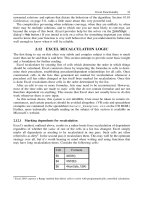
The two routers are connected as shown in Figure 3−17. RouterA and RouterB are connected to an Adtran
Atlas 800 ISDN switch.
Figure 3−17: ISDN BRI to ISDN PRI
A PC running a terminal emulation program should be connected to the console port of one of the routers
using a Cisco rolled cable.
Note A PRI is different from a BRI. A PRI is carried on a T1 circuit and consists of 23 B channels, each
carrying 56K or 64K of user traffic. A PRI has a 64K D channel used for signaling between the user
device and the ISDN switch. A BRI consists of two B channels, each carrying 56K or 64K of user
traffic. A BRI has a 16K D channel used for signaling between the user device and the ISDN switch.
Note A PRI ISDN circuit does not have a SPID associated with each B channel.
ISDN Switch Setup
If you do not have access to actual ISDN circuits, you can use an ISDN desktop switch. Information on
configuring an ISDN desktop switch can be found in the ISDN switch configuration section earlier in this
chapter.
Router Configuration
The configurations for the two routers in this example are as follows. ISDN commands are highlighted in
bold.
RouterA
RouterA#show run
Building configuration...
Current configuration:
!
version 11.2
no service udp−small−servers
67
no service tcp−small−servers
!
hostname RouterA
!
!
username RouterB password 7 121A0C041104
isdn switch−type basic−ni1 ← Set D channel call control
!
interface BRI0/0
ip address 196.1.1.1 255.255.255.0
encapsulation ppp
isdn spid1 8995101 5101 ← Set SPID value for both B channels
isdn spid2 8995102 5102
dialer idle−timeout 30 ← Define how many seconds to disconnect after last
interesting packet
dialer map ip 196.1.1.7 name RouterB broadcast 8991000 ← Associate next hop
address with a dial
string
dialer load−threshold 1 ← Define threshold to add additional B channels
dialer−group 1 ← Associate interface with dialer−list 1
no fair−queue
ppp authentication chap
ppp multilink ← Request a PPP multilink session
!
no ip classless
dialer−list 1 protocol ip permit ← Define interesting traffic
!
line con 0
line aux 0
line vty 0 4
login
!
end
RouterB
RouterB#show run
Building configuration...
Current configuration:
!
version 11.2
no service password−encryption
service udp−small−servers
service tcp−small−servers
!
hostname RouterB
!
enable password cisco
!
username RouterA password 0 cisco
isdn switch−type primary−5ess ← Set D channel call control for the PRI
!
controller T1 0
framing esf ← Set T1 Extended Superframe Framing
linecode b8zs ← Set T1 line coding
pri−group timeslots 1−24 ← Define entire T1 to belong to the PRI
!
interface Serial0:23 ← D channel of the PRI
ip address 196.1.1.7 255.255.255.0
encapsulation ppp
no ip mroute−cache
isdn incoming−voice modem
dialer idle−timeout 900 ← Set the interesting traffic timeout
dialer−group 1 ← Associate the interface with dialer−list 1
no fair−queue
no cdp enable
68
ppp authentication chap
ppp multilink
!
interface Dialer1
no ip address
encapsulation ppp
dialer in−band
dialer idle−timeout 900
dialer−group 1
no fair−queue
ppp authentication chap
!
no ip classless
ip route 192.1.5.0 255.255.255.0 196.1.1.1
dialer−list 1 protocol ip permit ← Define interesting traffic
!
line con 0
exec−timeout 60 0
password cisco
login
line aux 0
line vty 0 4
login
!
end
Notice that the configuration for the PRI interface on RouterB is quite different from a BRI configuration.
When configuring a PRI, you must first define a T1 controller interface and specify the proper T1 framing and
line coding. The PRI gets configured as a serial interface:23, specifying the D channel of the PRI interface.
Monitoring and Testing the Configuration
Let's start by connecting to RouterA and verifying that the BRI circuit is up and active. Type the show isdn
status command to display the status of the ISDN interface. We see that a SPID has been sent for both B
channels to the ISDN switch and has been validated. We also see under the layer 3 status that there are no
active calls on the router at this time.
RouterA#show isdn status
The current ISDN Switchtype = basic−ni1
ISDN BRI0/0 interface
Layer 1 Status:
ACTIVE
Layer 2 Status:
TEI = 64, State = MULTIPLE_FRAME_ESTABLISHED
TEI = 65, State = MULTIPLE_FRAME_ESTABLISHED
Spid Status:
TEI 64, ces = 1, state = 5(init)
spid1 configured, spid1 sent, spid1 valid
Endpoint ID Info: epsf = 0, usid = B, tid
TEI 65, ces = 2, state = 5(init)
spid2 configured, spid2 sent, spid2 valid
Endpoint ID Info: epsf = 0, usid = C, tid
Layer 3 Status:
0 Active Layer 3 Call(s) ← No active calls
Activated dsl 0 CCBs = 2
CCB:callid=0, sapi=0, ces=1, B−chan=0
CCB:callid=0, sapi=0, ces=1, B−chan=0
Total Allocated ISDN CCBs = 2
← B channel #1
= 1
← B channel #2
= 1
The status of the D channel of the BRI circuit can be displayed by typing show interface bri 0/0. We see that
the interface is in an up/up (spoofing) state, which indicates that the D channel is active.
RouterA#show interface bri 0/0
BRI0/0 is up, line protocol is up (spoofing) ← D channel of BRI
69
Hardware is QUICC BRI with U interface
Internet address is 196.1.1.1/24
MTU 1500 bytes, BW 64 Kbit, DLY 20000 usec, rely 255/255, load 1/255
Encapsulation PPP, loopback not set
.
.
We see from the show dialer command that the BRI interface will dial 8991000 to place its calls. The idle
timer is set to 30 seconds. This value is set by the dialer idle−timeout 30 statement in the configuration for
RouterA. It tells the router to disconnect a call 30 seconds after the last interesting packet has been received.
RouterA#show dialer
BRI0/0 − dialer type = ISDN
Dial String
Successes
Failures
8991000
5
0
0 incoming call(s) have been screened.
Last called
00:07:48
Last status
successful
BRI0/0:1 − dialer type = ISDN
Idle timer (30 secs), Fast idle timer (20 secs)
Wait for carrier (30 secs), Re−enable (15 secs)
Dialer state is idle
BRI0/0:2 − dialer type = ISDN
Idle timer (30 secs), Fast idle timer (20 secs)
Wait for carrier (30 secs), Re−enable (15 secs)
Dialer state is idle
Now let's connect to RouterB and view some PRI statistics. We will see that monitoring a PRI ISDN circuit is
slightly different than monitoring a BRI circuit. Type the show isdn status command. We see that although
there are 23 B channels, we will only get one Multiple_Frame_Established message. We also see that there
are no indications of valid SPIDs being sent. This is because an ISDN PRI circuit does not have any SPIDs
associated with it.
RouterB#show isdn status
The current ISDN Switchtype = primary−5ess
ISDN Serial0:23 interface
Layer 1 Status:
ACTIVE
Layer 2 Status:
TEI = 0, State = MULTIPLE_FRAME_ESTABLISHED
Layer 3 Status:
0 Active Layer 3 Call(s) ← No active calls at this time
Activated dsl 0 CCBs = 0
Total Allocated ISDN CCBs = 0
A PRI ISDN interface has an additional monitoring command. Type the show isdn service command. This
command displays the B channel status of the entire PRI circuit. The state line shows which channels are
currently connected, while the channel line shows which channels can accept or make a call. Possible states
are:
• Idle
• Busy
• Reserved
• Restart
• Maint
We see that each B channel is in an idle state (State=0). The last eight channels are in a state of 3, which is
reserved. These channels are used for an E1 PRI, which is the European counterpart to a T1. An E1 PRI has
31 B channels as opposed to the T1, which only has 23.
70
RouterB#show isdn service
PRI Channel Statistics:
ISDN Se0:23, Channel (1−31)
Activated dsl 0
State (0=Idle 1=Propose 2=Busy 3=Reserved 4=Restart 5=Maint)
0 0 0 0 0 0 0 0 0 0 0 0 0 0 0 0 0 0 0 0 0 0 0 3 3 3 3 3 3 3 3
Channel (1−31) Service (0=Inservice 1=Maint 2=Outofservice)
0 0 0 0 0 0 0 0 0 0 0 0 0 0 0 0 0 0 0 0 0 0 0 0 0 0 0 0 0 0 0
To display the status of the D channel of the PRI, use the show interfaces 0:23 command. The s 0
corresponds to the controller T1 0 command in the configuration for RouterB.
RouterB#show interface s 0:23
Serial0:23 is up, line protocol is up (spoofing) ← D channel of PRI
Hardware is DSX1 ← T1 interface
Internet address is 196.1.1.7/24
MTU 1500 bytes, BW 64 Kbit, DLY 20000 usec, rely 255/255, load 1/255
Encapsulation PPP, loopback not set
Last input 00:00:08, output 00:00:08, output hang never
Last clearing of "show interface" counters never
Queueing strategy: fifo
Output queue 0/40, 0 drops; input queue 0/75, 0 drops
5 minute input rate 0 bits/sec, 0 packets/sec
5 minute output rate 0 bits/sec, 0 packets/sec
1284 packets input, 5949 bytes, 0 no buffer
Received 0 broadcasts, 0 runts, 0 giants, 0 throttles
0 input errors, 0 CRC, 0 frame, 0 overrun, 0 ignored, 0 abort
1285 packets output, 5541 bytes, 0 underruns
0 output errors, 0 collisions, 5 interface resets
0 output buffer failures, 0 output buffers swapped out
1 carrier transitions
Timeslot(s) Used:24, Transmitter delay is 0 flags
The show dialer command will display the status of the dialer on the router. We notice some differences from
how this command looks when used on a BRI interface. When used on a PRI, the command will display the
status of each of the 23 B channels.
RouterB#show dialer
Dialer1 − dialer type = IN−BAND SYNC NO−PARITY
Idle timer (900 secs), Fast idle timer (20 secs)
Wait for carrier (30 secs), Re−enable (15 secs)
Dial String
Successes
Failures
Last called
Serial0:0 − dialer type = ISDN
Idle timer (900 secs), Fast idle timer (20 secs)
Wait for carrier (30 secs), Re−enable (15 secs)
Dialer state is idle
Serial0:1 − dialer type = ISDN
Idle timer (900 secs), Fast idle timer (20 secs)
Wait for carrier (30 secs), Re−enable (15 secs)
Dialer state is idle
.
.
.
.
.
Serial0:22 − dialer type = ISDN
Idle timer (900 secs), Fast idle timer (20 secs)
Wait for carrier (30 secs), Re−enable (15 secs)
Dialer state is idle
71
Last status
Serial0:23 − dialer type = ISDN
Dial String
Successes
Failures
0 incoming call(s) have been screened.
Last called
Last status
Turn on PPP authentication and ISDN Q931 call control debugging with the debug ppp authen command
and the debug isdn q931 command. The status of what debug commands are active can be displayed by
typing the show debug command. Remember to use the term mon command to display the debug output if
you are not connected to the console port of the router.
RouterA#show debug
PPP:
PPP authentication debugging is on
ISDN:
ISDN Q931 packets debugging is on
Now let's try to ping RouterB at IP address 196.1.1.7. We see that an ISDN call is made as soon as we start
our ping.
RouterA#ping 196.1.1.7
Type escape sequence to abort.
Sending 5, 100−byte ICMP Echos to 196.1.1.7, timeout is 2 seconds:
ISDN BR0/0: TX −> SETUP pd = 8 callref = 0x06 ← B channel #1
Bearer Capability I = 0x8890
Channel ID I = 0x83
Keypad Facility I = '98991000'
ISDN BR0/0: RX <− SETUP_ACK pd = 8 callref = 0x86
Channel ID I = 0x89.
ISDN BR0/0: RX <− CALL_PROC pd = 8 callref = 0x86
ISDN BR0/0: RX <− CONNECT pd = 8 callref = 0x86
Signal I = 0x3F − Tones off
%LINK−3−UPDOWN: Interface BRI0/0:1, changed state to up
PPP BRI0/0:1: treating connection as a callout
ISDN BR0/0: TX −> CONNECT_ACK pd = 8 callref = 0x06
PPP BRI0/0:1: Send CHAP Challenge id=5 ← Chap successful on B channel #1
PPP BRI0/0:1: CHAP Challenge id=6 received from RouterB
PPP BRI0/0:1: Send CHAP Response id=6
PPP BRI0/0:1: Passed CHAP authentication with remote
PPP BRI0/0:1: CHAP response received from RouterB
PPP BRI0/0:1: CHAP Response id=5 received from RouterB
PPP BRI0/0:1: Send CHAP Success id=5
PPP BRI0/0:1: remote passed CHAP authentication.
%LINK−3−UPDOWN: Interface Virtual−Access1, changed state to up
PPP Virtual−Access1: treating connection as a callin
%LINEPROTO−5−UPDOWN: Line protocol on Interface BRI0/0:1, changed state to up
%LINEPROTO−5−UPDOWN: Line protocol on Interface Virtual−Access1, changed state to up
ISDN BR0/0: TX −> SETUP pd = 8 callref = 0x07 ← B channel #2
Bearer Capability I = 0x8890
Channel ID I = 0x83
Keypad Facility I = '98991000'
ISDN BR0/0: RX <− SETUP_ACK pd = 8 callref = 0x87
Channel ID I = 0x8A
ISDN BR0/0: Event: incoming ces value = 2
%ISDN−6−CONNECT: Interface BRI0/0:1 is now connected to 98991000 RouterB
ISDN BR0/0: RX <− CALL_PROC pd = 8 callref = 0x87
ISDN BR0/0: Event: incoming ces value = 2
ISDN BR0/0: RX <− CONNECT pd = 8 callref = 0x87
Signal I = 0x3F − Tones off
ISDN BR0/0: Event: incoming ces value = 2
%LINK−3−UPDOWN: Interface BRI0/0:2, changed state to up
PPP BRI0/0:2: treating connection as a callout
ISDN BR0/0: TX −> CONNECT_ACK pd = 8 callref = 0x07
PPP BRI0/0:2: Send CHAP Challenge id=2
72
PPP BRI0/0:2: CHAP Challenge id=3 received from RouterB
PPP BRI0/0:2: Send CHAP Response id=3
PPP BRI0/0:2: Passed CHAP authentication with remote
PPP BRI0/0:2: CHAP response received from RouterB
PPP BRI0/0:2: CHAP Response id=2 received from RouterB
PPP BRI0/0:2: Send CHAP Success id=2 ← Chap successful on B channel #1
PPP BRI0/0:2: remote passed CHAP authentication.
%LINEPROTO−5−UPDOWN: Line protocol on Interface BRI0/0:2, changed state to up
%ISDN−6−CONNECT: Interface BRI0/0:2 is now connected to 98991000 RouterB
..!!!
Success rate is 60 percent (3/5), round−trip min/avg/max = 32/32/32 ms
RouterA#
Notice that the first two pings were not successful. This is because the router was still in the process of
establishing the ISDN call. Another ping to 196.1.1.7 would be 100−percent successful.
Let's verify that we have an MLPPP bundle between RouterA and RouterB. Type the show ppp multilink
command to view the status of the MLPPP Link. We see that there are two B channels in the MLPPP bundle.
These are the two B channels of the BRI.
RouterA#show ppp multi
Bundle RouterB, 2 members, Master link is Virtual−Access1
Dialer Interface is BRI0/0
0 lost fragments, 0 reordered, 0 unassigned, sequence 0xA/0xA rcvd/sent
0 discarded, 0 lost received, 1/255 load
Member Links: 2 ← B channel #1 and B channel #2
BRI0/0:1
BRI0/0:2
The show isdn status command can also be used to verify that we have two active calls on the router.
RouterA#show isdn status
The current ISDN Switchtype = basic−ni1
ISDN BRI0/0 interface
Layer 1 Status:
ACTIVE
Layer 2 Status:
TEI = 64, State = MULTIPLE_FRAME_ESTABLISHED
TEI = 65, State = MULTIPLE_FRAME_ESTABLISHED
Spid Status:
TEI 64, ces = 1, state = 5(init)
spid1 configured, spid1 sent, spid1 valid
Endpoint ID Info: epsf = 0, usid = B, tid = 1
TEI 65, ces = 2, state = 5(init)
spid2 configured, spid2 sent, spid2 valid
Endpoint ID Info: epsf = 0, usid = C, tid = 1
Layer 3 Status:
2 Active Layer 3 Call(s) ← Active call on both B channels
Activated dsl 0 CCBs = 4
CCB:callid=0, sapi=0, ces=1, B−chan=0
CCB:callid=0, sapi=0, ces=1, B−chan=0
CCB:callid=8006, sapi=0, ces=1, B−chan=1
CCB:callid=8007, sapi=0, ces=2, B−chan=2
Total Allocated ISDN CCBs = 4
After the idle timeout period of 30 seconds, RouterA will disconnect the ISDN call. This period is defined by
the dialer idle−timeout 30 statement on RouterA's configuration.
%LINEPROTO−5−UPDOWN: Line protocol on Interface
Virtual−Access1, changed state to down
%LINK−3−UPDOWN: Interface Virtual−Access1, changed state to down
73
%ISDN−6−DISCONNECT: Interface BRI0/0:1 disconnected from 98991000
RouterB, call lasted 55 seconds
%ISDN−6−DISCONNECT: Interface BRI0/0:2 disconnected from 98991000
RouterB, call lasted 51 seconds
ISDN BR0/0: TX −> DISCONNECT pd = 8 callref = 0x06 ← RouterA sends a
disconnect to the ISDN
switch for B channel #1
Cause i = 0x8090 − Normal call clearing
ISDN BR0/0: TX −> DISCONNECT pd = 8 callref = 0x07 ← RouterA sends a
disconnect to the ISDN
switch for B channel #2
Cause i = 0x8090 − Normal call clearing
ISDN BR0/0: RX <− RELEASE pd = 8 callref = 0x86
%LINK−3−UPDOWN: Interface BRI0/0:1, changed state to down
ISDN BR0/0: TX −> RELEASE_COMP pd = 8 callref = 0x06
ISDN BR0/0: RX <− RELEASE pd = 8 callref = 0x87
ISDN BR0/0: Event: incoming ces value = 2
%LINK−3−UPDOWN: Interface BRI0/0:2, changed state to down
ISDN BR0/0: TX −> RELEASE_COMP pd = 8 callref = 0x07
%LINEPROTO−5−UPDOWN: Line protocol on Interface BRI0/0:1,
changed state to down
%LINEPROTO−5−UPDOWN: Line protocol on Interface BRI0/0:2,
changed state to down
Now let's connect to RouterB and see what an incoming call looks like on the ISDN PRI interface. You can
either attach a second terminal to RouterB so that you can place a call on RouterA with a ping and monitor
RouterB at the same time or you can log the terminal output on RouterB to a log file.
Make sure that PPP authentication and ISDN Q931 call control debugging are enabled on RouterB by typing
the debug ppp authen and debug isdn q931 commands. You can verify what debug commands are enabled
on the router by typing the show debug command. Remember to use the term mon command to display the
debug output if you are not connected to the console port of the router.
RouterB#show debug
PPP:
PPP authentication debugging is on
ISDN:
ISDN Q931 packets debugging is on
The following is a trace on RouterB while a call is coming in from RouterA.
The D channel of the PRI is referenced as Se0:23
↓<ΛΙΝΕ/>ISDN Se0:23: RX <− SETUP pd = 8 callref = 0x0C
Bearer Capability i = 0x8890
Channel ID i = 0xA98393
Calling Party Number i = '!', 0x80, '8995201' ← Calling number
Called Party Number i = 0xA1, '8991000' ← Called number
The first call that comes into the PRI connects to channel 18
↓
%LINK−3−UPDOWN: Interface Serial0:18, changed state to up
Se0:18 PPP: Treating connection as a callin
ISDN Se0:23: TX −> CALL_PROC pd = 8 callref = 0x800C
Channel ID i = 0xA98393
ISDN Se0:23: TX −> CONNECT pd = 8 callref = 0x800C
Channel ID i = 0xA98393
ISDN Se0:23: RX <− CONNECT_ACK pd = 8 callref = 0x0C
Se0:18 PPP: Phase is AUTHENTICATING, by both
Se0:18 CHAP: O CHALLENGE id 7 len 29 from "RouterB"
Se0:18 CHAP: I CHALLENGE id 6 len 28 from "RouterA"
Se0:18 CHAP: Waiting for peer to authenticate first
Se0:18 CHAP: I RESPONSE id 7 len 28 from "RouterA"
Se0:18 CHAP: O SUCCESS id 7 len 4
Se0:18 CHAP: Processing saved Challenge, id 6
74
Se0:18 CHAP: O RESPONSE id 6 len 29 from "RouterB"
Se0:18 CHAP: I SUCCESS id 6 len 4
%LINK−3−UPDOWN: Interface Virtual−Access1, changed state to up
Vi1 PPP: Treating connection as a callin
%LINEPROTO−5−UPDOWN: Line protocol on Interface Serial0:18, changed state to up
%LINEPROTO−5−UPDOWN: Line protocol on Interface Virtual−Access1, changed
state to up
ISDN Se0:23: RX <− SETUP pd = 8 callref = 0x35
Bearer Capability i = 0x8890
Channel ID i = 0xA98394
Calling Party Number i = '!', 0x80, '8995201'
Called Party Number i = 0xA1, '8991000'
The second call that comes into the PRI connects to channel 19
↓
%LINK−3−UPDOWN: Interface Serial0:19, changed state to up
Se0:19 PPP: Treating connection as a callin
ISDN Se0:23: TX −> CALL_PROC pd = 8 callref = 0x8035
Channel ID i = 0xA98394
ISDN Se0:23: TX −> CONNECT pd = 8 callref = 0x8035
Channel ID i = 0xA98394
ISDN Se0:23: RX <− CONNECT_ACK pd = 8 callref = 0x35
Se0:19 PPP: Phase is AUTHENTICATING, by both
Se0:19 CHAP: O CHALLENGE id 4 len 29 from "RouterB"
Se0:19 CHAP: I CHALLENGE id 3 len 28 from "RouterA"
Se0:19 CHAP: Waiting for peer to authenticate first
Se0:19 CHAP: I RESPONSE id 4 len 28 from "RouterA"
Se0:19 CHAP: O SUCCESS id 4 len 4
Se0:19 CHAP: Processing saved Challenge, id 3
Se0:19 CHAP: O RESPONSE id 3 len 29 from "RouterB"
Se0:19 CHAP: I SUCCESS id 3 len 4
%LINEPROTO−5−UPDOWN: Line protocol on Interface Serial0:19, changed state to up
%ISDN−6−CONNECT: Interface Serial0:19 is now connected to 9148993601 RouterA
The show ppp multilink command on RouterB will reveal that two B channels are active in an MLPPP
bundle.
RouterB#show ppp multi
Bundle RouterA, 2 members, Master link is Virtual−Access1
Dialer Interface is Serial0:23
0 lost fragments, 0 reordered, 0 unassigned, sequence 0x0/0x0 rcvd/sent
0 discarded, 0 lost received, 1/255 load
Member Links: 2
Serial0:18
Serial0:19
Type the show dialer maps command to view the dynamic dialer map that gets created when RouterA dials
into RouterB.
RouterB#show dialer maps
Dynamic dialer map ip 196.1.1.1 name RouterA () on Serial0:23
The show isdn service command shows us that there are two active B channels on the PRI. The active
channels are denoted by a 2 in the appropriate channel position of the PRI.
RouterB#show isdn service
PRI Channel Statistics:
ISDN Se0:23, Channel (1−31)
Activated dsl 0
State (0=Idle 1=Propose 2=Busy 3=Reserved 4=Restart 5=Maint)
0 0 0 0 0 0 0 0 0 0 0 0 0 0 0 0 0 0 2 2 0 0 0 3 3 3 3 3 3 3 3
Channel (1−31) Service (0=Inservice 1=Maint 2=Outofservice)
0 0 0 0 0 0 0 0 0 0 0 0 0 0 0 0 0 0 0 0 0 0 0 0 0 0 0 0 0 0 0
75
When the call disconnects on the PRI, we see that channels 18 and 19 receive a disconnect message from the
ISDN switch. Remember that the far−end router (RouterA) is disconnecting the call so RouterB will receive a
Disconnect message from the network.
%LINK−3−UPDOWN: Interface Virtual−Access1, changed state to down
ISDN Se0:23: RX <− DISCONNECT pd = 8 callref = 0x0C ← Disconnect for
Channel 18
Cause i = 0x8090 − Normal call clearing
%ISDN−6−DISCONNECT: Interface Serial0:18 disconnected from 9148993601 RouterA,
call lasted 32 seconds
%LINK−3−UPDOWN: Interface Serial0:18, changed state to down
ISDN Se0:23: TX −> RELEASE pd = 8 callref = 0x800C
ISDN Se0:23: RX <− DISCONNECT pd = 8 callref = 0x35 ← Disconnect for
Channel 19
Cause i = 0x8090 − Normal call clearing
%ISDN−6−DISCONNECT: Interface Serial0:19 disconnected from 9148993601 RouterA,
call lasted 27 seconds
%LINK−3−UPDOWN: Interface Serial0:19, changed state to down
ISDN Se0:23: TX −> RELEASE pd = 8 callref = 0x8035
ISDN Se0:23: RX <− RELEASE_COMP pd = 8 callref = 0x0C
ISDN Se0:23: RX <− RELEASE_COMP pd = 8 callref = 0x35
%LINEPROTO−5−UPDOWN: Line protocol on Interface Serial0:18, changed state to down
%LINEPROTO−5−UPDOWN: Line protocol on Interface Serial0:19, changed state to down
%LINEPROTO−5−UPDOWN: Line protocol on Interface Virtual−Access1, changed state to down
Once the PRI call is disconnected, the show isdn service command output will reveal that there are no
connected B channels on the PRI.
RouterB#show isdn service
PRI Channel Statistics:
ISDN Se0:23, Channel (1−31)
Activated dsl 0
State (0=Idle 1=Propose 2=Busy 3=Reserved 4=Restart 5=Maint)
0 0 0 0 0 0 0 0 0 0 0 0 0 0 0 0 0 0 0 0 0 0 0 3 3 3 3 3 3 3 3
Channel (1−31) Service (0=Inservice 1=Maint 2=Outofservice)
0 0 0 0 0 0 0 0 0 0 0 0 0 0 0 0 0 0 0 0 0 0 0 0 0 0 0 0 0 0 0
Since the PRI interface on this router contains a full T1 CSU, you can type the show cont t 0 command to
view the status of the T1 ESF registers on the interface. Data is broken into the previous 24 hours of
performance information. The 24−hour statistics are broken up into 96 intervals, each representing 15 minutes
of error information.
RouterB#show cont t 0
T1 0 is up.
No alarms detected.
Framing is ESF, Line Code is B8ZS, Clock Source is Line.
Data in current interval (256 seconds elapsed):
0 Line Code Violations, 0 Path Code Violations
0 Slip Secs, 0 Fr Loss Secs, 0 Line Err Secs, 0 Degraded Mins
0 Errored Secs, 0 Bursty Err Secs, 0 Severely Err Secs, 0 Unavail Secs
Data in Interval 1: ← A single 15 minute interval
0 Line Code Violations, 0 Path Code Violations
0 Slip Secs, 0 Fr Loss Secs, 0 Line Err Secs, 0 Degraded Mins
0 Errored Secs, 0 Bursty Err Secs, 0 Severely Err Secs, 0 Unavail Secs
Data in Interval 2:
0 Line Code Violations, 0 Path Code Violations
0 Slip Secs, 0 Fr Loss Secs, 0 Line Err Secs, 0 Degraded Mins
0 Errored Secs, 0 Bursty Err Secs, 0 Severely Err Secs, 0 Unavail Secs
.
.
.
.
Total Data (last 13 15 minute intervals):
0 Line Code Violations, 0 Path Code Violations,
76
1 Slip Secs, 0 Fr Loss Secs, 0 Line Err Secs, 0 Degraded Mins,
0 Errored Secs, 0 Bursty Err Secs, 0 Severely Err Secs, 1 Unavail Secs
Lab #7: Snapshot Routing
Equipment Needed
The following equipment is needed to perform this lab exercise:
• Two Cisco routers, each of which must have a BRI interface
• Two ISDN BRI circuits
• Cisco IOS 11.3 or higher
• A PC running a terminal emulation program for console port connection on the routers
Configuration Overview
This lab will demonstrate snapshot routing. Snapshot routing allows an ISDN hub and spoke network to be
built without configuring and maintaining static routes. Snapshot is only supported for distance vector routing
protocols such as RIP and IGRP for IP traffic. Without snapshot routing, running RIP on an ISDN interface
would mean that every 30 seconds a call would be made (assuming a call was not already up) to exchange
updates. Snapshot defines an active period and a quiet period. During the active period, a RIP−enabled
snapshot router will exchange routing updates. If there are no active calls, the snapshot router will initiate an
ISDN call during the active period to send a routing update. During the quiet period, a snapshot router will not
initiate a call to send a routing update. Snapshot routing freezes entries in the routing table during the quiet
period. The active and quiet periods are user defined. The minimum active period is 5 minutes and the
minimum quiet period is 8 minutes.
Any calls that bring up the ISDN interface will also reset the snapshot routing process to the beginning of a
new active period.
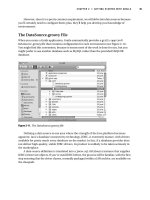
The two routers are connected as shown in Figure 3−18. RouterA and RouterB are connected to an Adtran
Atlas 800 ISDN switch.
Figure 3−18: Snapshot routing
A PC running a terminal emulation program should be connected to the console port of one of the routers
using a Cisco rolled cable.
Note Some versions of the IOS do not support snapshot routing with MLPPP. Do not use a ppp multilink
statement in your router configuration.
ISDN Switch Setup
If you do not have access to actual ISDN circuits, you can use an ISDN desktop switch. Information on
configuring an ISDN desktop switch can be found in the ISDN switch configuration section earlier in this
chapter.
77
Router Configuration
The configurations for the two routers in this example are as follows. ISDN commands are highlighted in
bold.
RouterA
RouterA#show run
Building configuration...
Current configuration:
!
version 11.3
service timestamps debug uptime
service timestamps log uptime
no service password−encryption
service udp−small−servers
service tcp−small−servers
!
hostname RouterA
!
enable password cisco
!
username RouterB password 0 cisco
isdn switch−type basic−ni ← Set the D channel call control
!
!
!
interface Loopback0
ip address 26.26.26.26 255.255.255.0
!
interface BRI0/0
ip address 196.1.1.26 255.255.255.0
encapsulation ppp
dialer map snapshot 1 name RouterB broadcast 8995201 ← Define the dial string
for snapshot updates
dialer map ip 196.1.1.29 name RouterB broadcast 8995201 ← Define next hop
address and dial
string
dialer−group 1 ← Associate this interface with dialer−list 1
isdn switch−type basic−ni
isdn spid1 5101 8995101 ← Define the SPID for both B channels
isdn spid2 5102 8995102
snapshot client 5 8 dialer ← Define this router as a snapshot client.
The active time is 5 minutes and the quiet time
is 8 minutes.
no fair−queue
no cdp enable
ppp authentication chap
!
interface Serial0/0
no ip address
!
router rip
network 26.0.0.0
network 196.1.1.0
!
no ip classless
!
dialer−list 1 protocol ip permit ← Define interesting traffic
!
line con 0
password cisco
login
line aux 0
line vty 0 4
78
login
!
end
RouterB
RouterB#show run
Building configuration...
Current configuration:
!
version 11.3
service timestamps debug uptime
service timestamps log uptime
no service password−encryption
!
hostname RouterB
!
enable password cisco
!
username RouterA password 7 060506324F41
isdn switch−type basic−ni ← Set the D channel call control
!
!
!
interface Loopback0
ip address 29.29.29.29 255.255.255.0
!
interface BRI0/0
ip address 196.1.1.29 255.255.255.0
encapsulation ppp
dialer map ip 196.1.1.26 name RouterA broadcast ← Define the next hop address
dialer−group 1 ← Associate this interface with dialer−list 1
isdn switch−type basic−ni
isdn spid1 5101 8995101 ← Define the SPID for both B channels
isdn spid2 5102 8995102
snapshot server 5 dialer ← Define this router as a snapshot server. The active
time of 5 minutes must match the active time on the
snapshot client
no fair−queue
no cdp enable
ppp authentication chap
hold−queue 75 in
!
router rip
network 29.0.0.0
network 196.1.1.0
!
no ip classless
!
dialer−list 1 protocol ip permit ← Define interesting traffic
!
line con 0
password cisco
login
line aux 0
line vty 0 4
password cisco
login
!
end
Monitoring and Testing the Configuration
Let's start by connecting to RouterB and verifying that the ISDN circuit is up and active. Type the show isdn
79
status command to view the ISDN BRI status information.
RouterB#show isdn status
Global ISDN Switchtype = basic−ni
ISDN BRI0/0 interface
dsl 0, interface ISDN Switchtype = basic−ni
Layer 1 Status:
ACTIVE
Layer 2 Status:
TEI = 64, Ces = 1, SAPI = 0, State = MULTIPLE_FRAME_ESTABLISHED
TEI = 65, Ces = 2, SAPI = 0, State = MULTIPLE_FRAME_ESTABLISHED
Spid Status:
TEI 64, ces = 1, state = 5(init)
spid1 configured, spid1 sent, spid1 valid
Endpoint ID Info: epsf = 0, usid = 0, tid = 1
TEI 65, ces = 2, state = 5(init)
spid2 configured, spid2 sent, spid2 valid
Endpoint ID Info: epsf = 0, usid = 1, tid = 1
Layer 3 Status:
0 Active Layer 3 Call(s)
Activated dsl 0 CCBs = 0
Total Allocated ISDN CCBs = 0
RouterB is provisioned for snapshot routing. Type the show snap command to view snapshot information.
We see that RouterB is a snapshot server.
RouterB#show snap
BRI0/0 is up, line protocol is up Snapshot server
Options: dialer support
Length of active period:
5 minutes
For ip address: 196.1.1.26
Current state: active, remaining time: 1 minute
Connected dialer interface:
BRI0/0:1
Now let's connect to RouterA. Verify that the ISDN circuit is active with the show isdn status command.
RouterA#show isdn status
Global ISDN Switchtype = basic−ni
ISDN BRI0/0 interface
dsl 0, interface ISDN Switchtype = basic−ni
Layer 1 Status:
ACTIVE
Layer 2 Status:
TEI = 80, Ces = 1, SAPI = 0, State = MULTIPLE_FRAME_ESTABLISHED
TEI = 89, Ces = 2, SAPI = 0, State = MULTIPLE_FRAME_ESTABLISHED
Spid Status:
TEI 80, ces = 1, state = 5(init)
spid1 configured, spid1 sent, spid1 valid
Endpoint ID Info: epsf = 0, usid = 0, tid = 1
TEI 89, ces = 2, state = 5(init)
spid2 configured, spid2 sent, spid2 valid
Endpoint ID Info: epsf = 0, usid = 1, tid = 1
Layer 3 Status:
0 Active Layer 3 Call(s)
Activated dsl 0 CCBs = 0
Total Allocated ISDN CCBs = 0
The show dialer maps command will display information about any dialer maps configured on the router. We
see that RouterA has two dialer maps configured. The first dialer map is a snapshot dialer map used for
snapshot routing. The second dialer map is the map used for defining the next hop address to RouterB.
RouterA#show dialer maps
Static dialer map snapshot 1 name RouterB broadcast (8995201) on BRI0/0
Static dialer map ip 196.1.1.29 name RouterB broadcast (8995201) on BRI0/0
80
We see from the show snap command on RouterA that RouterA is a snapshot client. RouterA is currently in
the quiet state. This means that Router A will not initiate an ISDN call to send out RIP routing updates.
RouterA#show snap
BRI0/0 is up, line protocol is up Snapshot client
Options: dialer support
Length of active period:
5 minutes
Length of quiet period:
8 minutes
Length of retry period:
8 minutes
For dialer address 1
Current state: quiet, remaining: 6 minutes
The quiet period is defined to be 8 minutes. During the quiet period, connect to RouterB and examine its
routing table. We see that the route to the loopback on RouterA (26.0.0.0/8 [120/1] via 196.1.1.26, 00:04:31,
BRI0/0) is being aged, but is not being deleted from the routing table. Without snapshot, the route would be
deleted as soon as the BRI disconnected. With snapshot, the route is kept in the routing table and is not
deleted.
RouterB#show ip route
Codes: C − connected, S − static, I − IGRP, R − RIP, M − mobile, B − BGP
D − EIGRP, EX − EIGRP external, O − OSPF, IA − OSPF inter area
N1 − OSPF NSSA external type 1, N2 − OSPF NSSA external type 2
E1 − OSPF external type 1, E2 − OSPF external type 2, E − EGP
i − IS−IS, L1 − IS−IS level−1, L2 − IS−IS level−2, * − candidate default
U − per−user static route, o − ODR
Gateway of last resort is not set
C
R
C
196.1.1.0/24 is directly connected, BRI0/0
26.0.0.0/8 [120/1] via 196.1.1.26, 00:04:31, BRI0/0
29.0.0.0/24 is subnetted, 1 subnets
29.29.29.0 is directly connected, Loopback0
We see that the route ages to 7 minutes and 58 seconds. Notice that it is still in the routing table. Without
snapshot, a route would have been removed from the routing table if an update had not been received for this
amount of time.
RouterB#show ip route
Codes: C − connected, S − static, I − IGRP, R − RIP, M − mobile, B − BGP
D − EIGRP, EX − EIGRP external, O − OSPF, IA − OSPF inter area
N1 − OSPF NSSA external type 1, N2 − OSPF NSSA external type 2
E1 − OSPF external type 1, E2 − OSPF external type 2, E − EGP
i − IS−IS, L1 − IS−IS level−1, L2 − IS−IS level−2, * − candidate default
U − per−user static route, o − ODR
Gateway of last resort is not set
C
R
C
196.1.1.0/24 is directly connected, BRI0/0
26.0.0.0/8 [120/1] via 196.1.1.26, 00:07:58, BRI0/0
29.0.0.0/24 is subnetted, 1 subnets
29.29.29.0 is directly connected, Loopback0
The snapshot timers will continue to decrement. After 6 more minutes, the timer will show zero minutes.
RouterA#show snap
BRI0/0 is up, line protocol is upSnapshot client
Options: dialer support
Length of active period:
5 minutes
Length of quiet period:
8 minutes
Length of retry period:
8 minutes
For dialer address 1
Current state: quiet, remaining: 0 minutes
81
After the quiet period expires, snapshot will enter the active period. RouterA will now initiate an ISDN call to
send out routing updates.
21:09:39: %LINK−3−UPDOWN: Interface BRI0/0:1, changed state to up
21:09:39: %LINK−3−UPDOWN: Interface Virtual−Access1, changed state to up
21:09:39: RT: network 196.1.1.0 is now variably masked
21:09:39: RT: add 196.1.1.29/32 via 0.0.0.0, connected metric [0/0]
21:09:39: %LINEPROTO−5−UPDOWN: Line protocol on Interface BRI0/0:1, changed stat
e to up
21:09:39: %LINEPROTO−5−UPDOWN: Line protocol on Interface Virtual−Access1, chang
ed state to up
21:09:45: %ISDN−6−CONNECT: Interface BRI0/0:1 is now connected to 8995201
RouterB
The show snap command now shows that RouterA is in the 5−minute active period during which it will send
out RIP updates. If the ISDN circuit is not connected, snapshot will initiate the ISDN circuit to place the call.
RouterA#show snap
BRI0/0 is up, line protocol is up Snapshot client
Options: dialer support
Length of active period:
5 minutes
Length of quiet period:
8 minutes
Length of retry period:
8 minutes
For dialer address 1
Current state: active, remaining/exchange time: 5/0 minutes
Connected dialer interface:
BRI0/0:1
Updates received this cycle: ip
Now that snapshot is in the active state, reconnect to RouterB and view the routing table with the show ip
route command. Notice that the route to RouterA is still in the table but it has now been updated in the last 6
seconds. Since snapshot is in the active state, it is now sending RIP updates again.
RouterB#show ip route
Codes: C − connected, S − static, I − IGRP, R − RIP, M − mobile, B − BGP
D − EIGRP, EX − EIGRP external, O − OSPF, IA − OSPF inter area
N1 − OSPF NSSA external type 1, N2 − OSPF NSSA external type 2
E1 − OSPF external type 1, E2 − OSPF external type 2, E − EGP
i − IS−IS, L1 − IS−IS level−1, L2 − IS−IS level−2, * − candidate default
U − per−user static route, o − ODR
Gateway of last resort is not set
C
C
R
C
196.1.1.0/24 is variably subnetted, 2 subnets, 2 masks
196.1.1.0/24 is directly connected, BRI0/0
196.1.1.26/32 is directly connected, BRI0/0
26.0.0.0/8 [120/1] via 196.1.1.26, 00:00:06, BRI0/0
29.0.0.0/24 is subnetted, 1 subnets
29.29.29.0 is directly connected, Loopback0
Lab #8: OSPF Demand Circuits
Equipment Needed
The following equipment is needed to perform this lab exercise:
• Two Cisco routers, each of which must have a single ISDN BRI interface. One of the routers also
needs an Ethernet interface
• Cisco IOS 11.2 or higher
• Two ISDN BRI circuits
82
• A PC running a terminal emulation program for console port connection on the routers
Configuration Overview
This configuration will demonstrate an OSPF demand circuit. With OSPF demand circuits, periodic hellos are
suppressed and periodic refreshes of LSAs are not flooded over the ISDN link. The ISDN link will be brought
up initially to exchange routing information. After initial route exchanges, the link will only be activated
when there is a change in the routing topology. Without demand circuits, the OSPF periodic hello and LSA
updates will keep the ISDN circuit active even though there are no changes to the routing table.
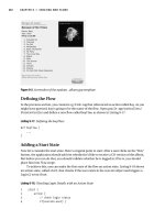
RouterA and RouterB are connected as shown in Figure 3−19.
Figure 3−19: OSPF demand circuits
A PC running a terminal emulation program should be connected to the console port of one of the routers
using a Cisco rolled cable.
ISDN Switch Setup
If you do not have access to actual ISDN circuits, you can use an ISDN desktop switch. Information on
configuring an ISDN desktop switch can be found in the ISDN switch configuration section earlier in this
chapter.
Router Configuration
The configurations for the two routers in this example are as follows. OSPF demand commands are
highlighted in bold.
RouterA
Current configuration:
!
version 12.1
service timestamps debug uptime
service timestamps log uptime
no service password−encryption
!
hostname RouterA
!
!
username RouterB password 0 cisco
!
ip subnet−zero
!
lane client flush
isdn switch−type basic−ni
cns event−service server
!
interface Loopback0
ip address 1.1.1.1 255.255.255.255
!
interface Ethernet0/0
83
ip address 135.25.2.1 255.255.252.0
no keepalive
!
interface BRI1/0
ip address 135.2.4.1 255.255.252.0
encapsulation ppp
ip ospf demand−circuit ← RouterA is configured with the ip ospf demand−circuit
command
dialer map ip 135.2.4.2 name RouterB broadcast 8995201
dialer load−threshold 255 either
dialer−group 1
isdn switch−type basic−ni
isdn spid1 5101 8995101
isdn spid2 5102 8995102
ppp authentication chap
!
router ospf 64
network 1.0.0.0 0.255.255.255 area 0
network 135.0.0.0 0.255.255.255 area 0
!
ip classless
no ip http server
!
access−list 100 permit ip any any
access−list 100 permit icmp any any
dialer−list 1 protocol ip list 100
!
line con 0
transport input none
line aux 0
line vty 0 4
login
!
end
RouterB
Current configuration:
!
version 12.1
service timestamps debug uptime
service timestamps log uptime
no service password−encryption
!
hostname RouterB
!
username RouterA password 0 cisco
!
ip subnet−zero
!
lane client flush
isdn switch−type basic−ni
cns event−service server
!
interface Loopback0
ip address 2.2.2.2 255.255.255.255
!
interface BRI1/0
ip address 135.2.4.2 255.255.252.0
encapsulation ppp
dialer map ip 135.2.4.1 name RouterA broadcast
dialer load−threshold 255 either
dialer−group 1
isdn switch−type basic−ni
isdn spid1 5201 8995201
isdn spid2 5202 8995202
ppp authentication chap
84
!
router ospf 64
network 2.0.0.0 0.255.255.255 area 0
network 135.0.0.0 0.255.255.255 area 0
!
ip classless
no ip http server
!
dialer−list 1 protocol ip permit
!
line con 0
transport input none
line aux 0
line vty 0 4
login
!
end
Monitoring and Testing the Configuration
Let's start by connecting to RouterA. Verify that the ISDN circuit is up and active with the show isdn status
command. We see that both SPIDs have been sent to the switch and are valid. Also notice that there are no
active calls on RouterA. This is important to note since we are running OSPF over the ISDN interface. We
will see shortly that our routing table is maintaining active OSPF routes without keeping the ISDN circuit
active at all times.
RouterA# show isdn status
Global ISDN Switchtype = basic−ni
ISDN BRI1/0 interface
dsl 8, interface ISDN Switchtype = basic−ni
Layer 1 Status:
ACTIVE
Layer 2 Status:
TEI = 64, Ces = 1, SAPI = 0, State = MULTIPLE_FRAME_ESTABLISHED
TEI = 65, Ces = 2, SAPI = 0, State = MULTIPLE_FRAME_ESTABLISHED
TEI 64, ces = 1, state = 5(init)
spid1 configured, spid1 sent, spid1 valid
Endpoint ID Info: epsf = 0, usid = 70, tid = 1
TEI 65, ces = 2, state = 5(init)
spid2 configured, spid2 sent, spid2 valid
Endpoint ID Info: epsf = 0, usid = 70, tid = 2
Layer 3 Status:
0 Active Layer 3 Call(s)
Activated dsl 8 CCBs = 0
The Free Channel Mask: 0x80000003
Total Allocated ISDN CCBs = 0
Let's view the routing table on RouterA with the show ip route command. We see that RouterA has learned
about the 2.2.2.2 network via the BRI interface. Recall that the BRI interface is not currently active (no calls
exist on the router). When RouterA initially powers on, the ISDN circuit will activate so that OSPF routes can
be exchanged. After the initial exchange of routes, OSPF demand will bring down the ISDN call. The before
OSPF demand circuit keeps the routing table entries active even though the ISDN circuit is not active. OSPF
keepalive messages are suppressed.
RouterA#show ip route
Codes: C − connected, S − static, I − IGRP, R − RIP, M − mobile, B − BGP
D − EIGRP, EX − EIGRP external, O − OSPF, IA − OSPF inter area
N1 − OSPF NSSA external type 1, N2 − OSPF NSSA external type 2
E1 − OSPF external type 1, E2 − OSPF external type 2, E − EGP
i − IS−IS, L1 − IS−IS level−1, L2 − IS−IS level−2, ia − IS−IS inter area
* − candidate default, U − per−user static route, o − ODR
P − periodic downloaded static route
Gateway of last resort is not set
85
C
O
C
C
1.0.0.0/32 is subnetted, 1 subnets
1.1.1.1is directly connected, Loopback0
2.0.0.0/32 is subnetted, 1 subnets
2.2.2.2 [110/1563] via 135.2.4.2, 00:06:07, BRI1/0
135.25.0.0/22 is subnetted, 1 subnets
135.25.0.0 is directly connected, Ethernet0/0
135.2.0.0/22 is subnetted, 1 subnets
135.2.4.0 is directly connected, BRI1/0
Let's get some information on the OSPF configuration of RouterA with the show ip ospf interface bri 1/0
command. We see that the interface is configured as a demand circuit. We also see that the OSPF hello
messages are being suppressed. RouterA is keeping its OSPF adjacencies even though the ISDN circuit is not
active.
RouterA#sh ip ospf int bri 1/0
BRI1/0 is up, line protocol is up (spoofing)
Internet Address 135.2.4.1/22, Area 0
Process ID 64, Router ID 1.1.1.1, Network Type POINT_TO_POINT, Cost: 1562
Configured as demand circuit.
Run as demand circuit.
DoNotAge LSA allowed.
Transmit Delay is 1 sec, State POINT_TO_POINT,
Timer intervals configured, Hello 10, Dead 40, Wait 40, Retransmit 5
Hello due in 00:00:00
Index 3/3 , flood queue length 0
Next 0x0(0)/0x0(0)
Last flood scan length is 1, maximum is 1
Last flood scan time is 0 msec, maximum is 0 msec
Neighbor Count is 1, Adjacent neighbor count is 1
Adjacent with neighbor 2.2.2.2 (Hello suppressed)
Suppress hello for 1 neighbor(s)
Now let's connect to RouterB. Verify that the ISDN circuit is active on RouterB with the show isdn status
command. Also notice that there are no active calls on RouterB.
RouterB#show isdn status
Global ISDN Switchtype = basic−ni
ISDN BRI1/0 interface
dsl 8, interface ISDN Switchtype = basic−ni
Layer 1 Status:
ACTIVE
Layer 2 Status:
TEI = 64, Ces = 1, SAPI = 0, State = MULTIPLE_FRAME_ESTABLISHED
TEI 64, ces = 1, state = 5(init)
spid1 configured, spid1 sent, spid1 valid
Endpoint ID Info: epsf = 0, usid = 70, tid = 1
TEI Not Assigned, ces = 2, state = 3(await establishment)
spid2 configured, spid2 NOT sent, spid2 NOT valid
Layer 3 Status:
0 Active Layer 3 Call(s)
Activated dsl 8 CCBs = 0
The Free Channel Mask: 0x80000003
Total Allocated ISDN CCBs = 0
Let's view the routing table on RouterB with the show ip route command. Notice that RouterB is learning
about the 1.1.1.1 and the 135.25.0.0 network via the ISDN interface. Notice that these routes are still being
maintained in the routing table even though the ISDN interface is not active.
RouterB#show ip route
Codes: C − connected, S − static, I − IGRP, R − RIP, M − mobile, B − BGP
D − EIGRP, EX − EIGRP external, O − OSPF, IA − OSPF inter area
N1 − OSPF NSSA external type 1, N2 − OSPF NSSA external type 2
E1 − OSPF external type 1, E2 − OSPF external type 2, E − EGP
i − IS−IS, L1 − IS−IS level−1, L2 − IS−IS level−2, ia − IS−IS inter area
86