all in one cisco ccie lab study guide second edition phần 3 pptx
Bạn đang xem bản rút gọn của tài liệu. Xem và tải ngay bản đầy đủ của tài liệu tại đây (651.24 KB, 89 trang )
input pkts 5
out bytes 520
in BECN pkts 0
in DE pkts 0
pvc create time 00:39:19,
output pkts 5
dropped pkts 0
out FECN pkts 0
out DE pkts 0
last time pvc status changed
in bytes 520
in FECN pkts 0
out BECN pkts 0
00:39:19
Now let's issue an extended ping with 10 ping packtets sent, each ping packet being 500 bytes.
RouterB#ping
Protocol [ip]:
Target IP address: 192.1.1.1
Repeat count [5]: 10
Datagram size [100]: 500
Timeout in seconds [2]:
Extended commands [n]:
Sweep range of sizes [n]:
Type escape sequence to abort.
Sending 10, 500−byte ICMP Echos to 192.1.1.1, timeout is 2 seconds:
!!!!!!!!!!
Success rate is 100 percent (10/10), round−trip min/avg/max = 256/257/260 ms
The show frame pvc command will now show 15 input and output packets. This is 10 more that the last time
we examined the values. Remember that our extended ping was 10 packets. Notice that the command output
shows no input or output DE packets.
RouterB#sh frame pvc
PVC Statistics for interface Serial0/0 (Frame Relay DTE)
DLCI = 200, DLCI USAGE = LOCAL, PVC STATUS = ACTIVE, INTERFACE = Serial0/0
input pkts 15
output pkts 15
in bytes 5560
out bytes 5560
dropped pkts 0
in FECN pkts 0
in BECN pkts 0
out FECN pkts 0
out BECN pkts 0
in DE pkts 0
out DE pkts 0
pvc create time 00:39:39, last time pvc status changed 00:39:39
Now let's do another extended ping. Ping the far−end address of RouterA at 192.1.1.1. This time we will use a
datagram size of 512 bytes.
RouterB#ping
Protocol [ip]:
Target IP address: 192.1.1.1
Repeat count [5]: 10
Datagram size [100]: 512
Timeout in seconds [2]:
Extended commands [n]:
Sweep range of sizes [n]:
Type escape sequence to abort.
Sending 10, 512−byte ICMP Echos to 192.1.1.1, timeout is 2 seconds:
!!!!!!!!!!
Success rate is 100 percent (10/10), round−trip min/avg/max = 260/263/264 ms
Now type the show frame pvc command. Notice that our input and output packets have increased by 10, from
15 to 25. Also notice that we now have 10 output DE packets. This occurred because we exceeded our
512−byte limit for non−DE frames going out of the router.
RouterB#sh frame pvc
PVC Statistics for interface Serial0/0 (Frame Relay DTE)
DLCI = 200, DLCI USAGE = LOCAL, PVC STATUS = ACTIVE, INTERFACE = Serial0/0
input pkts 25
output pkts 25
in bytes 10720
151
out bytes 10720
dropped pkts 0
in FECN pkts 0
in BECN pkts 0
out FECN pkts 0
out BECN pkts 0
in DE pkts 0
out DE pkts 10
pvc create time 00:39:58, last time pvc status changed 00:39:58
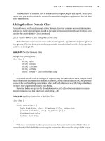
The following analyzer trace shows what a frame looks like that has its DE bit set.
Port A DTE ID=54, 01/25/99, 16:19:25.718925
Length=106, Good FCS
FRAME RELAY PROTOCOL
DLCI_msb
DLCI_lsb
DLCI
CR
EA
FECN
BECN
DE
EA
NLPID − NETWORK LEVEL PROTOCOL ID
Ethertype
IP − INTERNET PROTOCOL
Version
IHL (in 32 bit words)
Precedence
D(elay)
T(hroughput)
R(eliability)
Total Length (in octets)
Identification
D(on't) F(ragment)
M(ore) F(ragments)
Fragment Offset (in 8 octets)
Time To Live (in seconds)
Protocol
Header Checksum
Class C Source IP Address
Source Net ID
Source Host ID
Source Addr
Class C Destination IP Address
Destination Net ID
Destination Host ID
Destination Addr
ICMP − INTERNET CONTROL MESSAGE PROTOCOL
Type
Code
Checksum
ID
Sequence No
Dump
00000
0000 0000 6BF1
00010
ABCD ABCD ABCD
00020
ABCD ABCD ABCD
00030
ABCD ABCD ABCD
00040
ABCD ABCD ABCD
00050
ABCD ABCD ABCD
00060
ABCD ABCD ABCD
00070
ABCD
FCS
06h
4h
100
0
0
0
0
1
1
DOD IP 0800h
4
5
Routine 0h
Normal 0
Normal 0
Normal 0
100
0212h
No 0
No 0
0
255
ICMP 01h
316Bh
196865
12
195.1.1.12
196865
13
195.1.1.13
Echo 08h
00h
AA4Dh
0004h
23FFh
4408
ABCD
ABCD
ABCD
ABCD
ABCD
ABCD
152
ABCD
ABCD
ABCD
ABCD
ABCD
ABCD
ABCD
....k.D...
..........
..........
..........
..........
..........
..........
..
Good 2834h
Lab #15: Frame Relay Map Statements
Equipment Needed
The following equipment is needed to perform this lab exercise:
• Three Cisco routers, two of which must have at least one serial port, and one of which must have two
serial ports
• Cisco IOS 11.2 or higher
• A PC running a terminal emulation program for console port connection to the routers
• Two Cisco DTE/DCE crossover cables. If no crossover cables are available, you can make a
crossover cable by connecting a standard Cisco DTE cable to a standard Cisco DCE cable
Configuration Overview
This configuration will demonstrate the use of the Frame Relay map statement. A Frame Relay map is used
when connecting to a device that does not respond to an inverse ARP request. Since the device does not
respond to inverse ARP, the router cannot automatically resolve the local DLCI to the far−end IP address.
Configuring a Frame Relay map statement causes the router to install a static mapping to the far−end device.
This static mapping contains the local DLCI and the far−end IP address. Frame Relay maps can be used for
many other protocols, such as IPX.
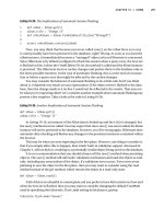
The three routers are connected as shown in Figure 4−15. Two of the routers are configured as Frame Relay
DTE devices. The third router is configured as a Frame Relay switch. The router configured as a Frame Relay
switch is also configured to supply clock to the DTE routers. This is accomplished via the use of a Cisco DCE
cable and a clock rate statement in the router's configuration.
Figure 4−15: Frame Relay map statements
Note
Keep in mind that although a Cisco router can act as a Frame Relay switch, this feature is
typically only used in test and demonstration situations such as this lab.
Note
The DCE side of the V.35 crossover cables must be connected to the router
FrameSwitch.
Router Configuration
The initial configurations for the three routers in this example are as follows. Key Frame Relay commands are
in bold.
FrameSwitch (Frame Relay Switch)
Current configuration:
!
version 11.2
no service udp−small−servers
no service tcp−small−servers
!
153
hostname FrameSwitch
!
!
frame−relay switching ← Configure Frame Relay Switching on this router
!
interface Serial0/0
no ip address
encapsulation frame−relay ← Set the interface encapsulation to Frame Relay
clockrate 64000
frame−relay lmi−type ansi ← Set the LMI type to Annex D
frame−relay intf−type dce ← Set the interface type to a DCE
frame−relay route 200 interface Serial0/1 201 ← Define a PVC between S0/0 and 0/1
!
interface Serial0/1
no ip address
encapsulation frame−relay
clockrate 64000
frame−relay lmi−type ansi
frame−relay intf−type dce
frame−relay route 201 interface Serial0/0 200
!
no ip classless
!
line con 0
line aux 0
line vty 0 4
login
!
end
RouterA (Frame Relay DTE)
Current configuration:
!
version 11.2
service timestamps debug datetime localtime
no service udp−small−servers
no service tcp−small−servers
!
hostname RouterA
!
enable password cisco
!
interface Serial0/0
ip address 192.1.1.1 255.255.255.0
encapsulation frame−relay
no frame−relay inverse−arp ← Disable Frame Relay inverse ARP support on this
interface
frame−relay lmi−type ansi
!
router rip
network 192.1.1.0
!
no ip classless
!
line con 0
line aux 0
line vty 0 4
password cisco
login
!
end
154
RouterB (Frame Relay DTE)
Current configuration:
!
version 11.2
no service udp−small−servers
no service tcp−small−servers
!
hostname RouterB
!
enable password cisco
!
interface Serial0/0
ip address 192.1.1.3 255.255.255.0
encapsulation frame−relay
no frame−relay inverse−arp ← Disable Frame Relay inverse ARP support on this interface
frame−relay lmi−type ansi
!
no ip classless
!
line con 0
line aux 0
line vty 0 4
password cisco
login
!
end
Notice that RouterA and RouterB both have the statement no frame−relay inverse−arp under their serial 0/0
interfaces. This command will stop the router from sending out an inverse ARP request on its local DLCIs.
Some networking devices do not respond to inverse ARP requests, so another way must be used to tell the
router what far−end IP address corresponds to each local DLCI.
Monitoring and Testing the Configuration
Let's begin by connecting to the router FrameSwitch and verifying that it is working properly. Issue the show
frame pvc command to display all DLCIs that are passing through the router.
FrameSwitch#sh frame pvc
PVC Statistics for interface Serial0/0
(Frame Relay DCE)
DLCI = 200, DLCI USAGE = SWITCHED, PVC STATUS = ACTIVE, INTERFACE = Serial0/0
input pkts 0
output pkts 0
in bytes 0
out bytes 0
dropped pkts 0
in FECN pkts 0
in BECN pkts 0
out FECN pkts 0
out BECN pkts 0
in DE pkts 0
out DE pkts 0
pvc create time 00:03:24, last time pvc status changed 00:02:40
Num Pkts Switched 0
PVC Statistics for interface Serial0/1
(Frame Relay DCE)
DLCI = 201, DLCI USAGE = SWITCHED, PVC STATUS = ACTIVE, INTERFACE = Serial0/1
input pkts 0
output pkts 0
in bytes 0
out bytes 0
dropped pkts 0
in FECN pkts 0
in BECN pkts 0
out FECN pkts 0
out BECN pkts 0
in DE pkts 0
out DE pkts 0
pvc create time 00:02:45, last time pvc status changed 00:02:41
Num Pkts Switched 0
We see that DLCI 200 is active on port S0/0 and DLCI 201 is active on port S0/1. Several items indicate that
ports S0/0 and S0/1 are acting as Frame Relay switch ports. These include the DLCI usage being referenced
155
as switched, the interface being referred to as a Frame Relay DCE, and the indication of Num Pkts Switched.
The PVC status should indicate Active.
Next issue the show frame route command. This command will display all active PVCs that are defined on
the router.
FrameSwitch#sh
Input Intf
Serial0/0
Serial0/1
frame route
Input Dlci
200
201
Output Intf
Serial0/1
Serial0/0
Output Dlci
201
200
Status
active
active
We see that two DLCIs are configured on this router, 200 and 201. The Frame Relay route table can be
interpreted as follows: Any traffic coming into interface S0/0 with a DLCI of 200 will be sent out interface
S0/1 with a DLCI of 201. Any traffic coming into interface S0/1 with a DLCI of 201 will be sent out interface
S0/0 with a DLCI of 200. The status of both DLCIs should be active.
The show interface s0/0 and show interface s0/1 commands will display the statuses of the serial interfaces
on the router. Several important Frame Relay parameters are displayed by this command and are highlighted
in bold including the interface encapsulation (Frame−Relay), the LMI status (LMI up), the fact that this port is
acting as a Frame Relay DCE, the LMI signaling type (ANSI Annex D), and the LMI exchange counters.
FrameSwitch#sh int s 0/0
Serial0/0 is up, line protocol is up
Hardware is QUICC Serial
MTU 1500 bytes, BW 1544 Kbit, DLY 20000 usec, rely 255/255, load 1/255
Encapsulation FRAME−RELAY, loopback not set, keepalive set (10 sec)
LMI enq sent 0, LMI stat recvd 0, LMI upd recvd 0
LMI enq recvd 297, LMI stat sent 297, LMI upd sent 0, DCE LMI up
LMI DLCI 0 LMI type is ANSI Annex D frame relay DCE
.
.
FrameSwitch#sh int s 0/1
Serial0/1 is up, line protocol is up
Hardware is QUICC Serial
MTU 1500 bytes, BW 1544 Kbit, DLY 20000 usec, rely 255/255, load 1/255
Encapsulation FRAME−RELAY, loopback not set, keepalive set (10 sec)
LMI enq sent 0, LMI stat recvd 0, LMI upd recvd 0
LMI enq recvd 301, LMI stat sent 301, LMI upd sent 0, DCE LMI up
LMI DLCI 0 LMI type is ANSI Annex D frame relay DCE
.
.
Now let's connect to RouterA. Verify that RouterA uses DLCI 200 as its local DLCI:
RouterA#sh frame pvc
PVC Statistics for interface Serial0/0 (Frame Relay DTE)
DLCI = 200, DLCI USAGE = UNUSED, PVC STATUS = ACTIVE, INTERFACE = Serial0/0
input pkts 0
output pkts 0
in bytes 0
out bytes 0
dropped pkts 0
in FECN pkts 0
in BECN pkts 0
out FECN pkts 0
out BECN pkts 0
in DE pkts 0
out DE pkts 0
pvc create time 00:02:03, last time pvc status changed 00:01:23
Num Pkts Switched 0
Display the results of the router's inverse ARP with the show frame map command.
RouterA#sh fra map
RouterA#
156
Notice how there is no output from the router. This is because we have disabled inverse ARP on this router.
Even though the router learns about new DLCIs from the switch, it will still not inverse ARP on these DLCIs
to learn the far−end IP address. In the case of RouterA, the router will not inverse ARP on DLCI 200.
Now turn on Frame Relay packet debugging on RouterA. Remember that debug messages only appear on the
console. If you are telneted into the router or connected to the AUX port, you will also need to issue the term
mon command.
RouterA#debug frame packet
Frame Relay packet debugging is on
Verify what debug items are enabled by typing the show debug command.
RouterA#sh debug
Frame Relay:
Frame Relay packet debugging is on
Now try to ping RouterB at its address of 192.1.1.3. The ping to 192.1.1.3 fails.
RouterA#ping 192.1.1.3
Type escape sequence to abort.
Sending 5, 100−byte ICMP Echos to 192.1.1.3, timeout is 2 seconds:
*Mar 1 00:52:56: Serial0/0:Encaps
*Mar 1 00:52:58: Serial0/0:Encaps
*Mar 1 00:53:00: Serial0/0:Encaps
*Mar 1 00:53:02: Serial0/0:Encaps
*Mar 1 00:53:04: Serial0/0:Encaps
Success rate is 0 percent (0/5)
failed−−no
failed−−no
failed−−no
failed−−no
failed−−no
map
map
map
map
map
entry
entry
entry
entry
entry
link
link
link
link
link
7(IP)
7(IP).
7(IP).
7(IP).
7(IP).
Let's examine the output of the debug command. The ping command attempted to send five ICMP echo
packets to 192.1.1.3. Each packet that was sent generated a debug statement saying that there was an
encapsulation failure with no map entry link. The router cannot send the ping packet to 192.1.1.3 because it
does not have a Frame Relay map to 192.1.1.3.
Now let's connect to RouterB. Verify that there is no Frame Relay map with the show frame map command.
RouterB#sh frame map
The show frame pvc command will verify that DLCI 201 is being used as the local DLCI. Remember that the
router will not inverse ARP on this DLCI, since inverse ARP has been disabled.
RouterB#sh frame pvc
PVC Statistics for interface Serial0/0 (Frame Relay DTE)
DLCI = 201, DLCI USAGE = UNUSED, PVC STATUS = ACTIVE, INTERFACE = Serial0/0
input pkts 0
output pkts 0
in bytes 0
out bytes 0
dropped pkts 0
in FECN pkts 0
in BECN pkts 0
out FECN pkts 0
out BECN pkts 0
in DE pkts 0
out DE pkts 0
pvc create time 00:03:09, last time pvc status changed 00:03:09
Num Pkts Switched 0
Turn on Frame Relay packet debugging on RouterB with the debug frame packet command.
RouterB#debug frame packet
Frame Relay packet debugging is on
157
Attempt to ping RouterA at IP address 192.1.1.1.
RouterB#ping 192.1.1.1
Notice that RouterB has the same problem as RouterA. Neither router knows how to reach the far−end router.
Type escape sequence to abort.
Sending 5, 100−byte ICMP Echos to 192.1.1.1, timeout is 2 seconds:
Serial0/0:Encaps failed−−no map
Serial0/0:Encaps failed−−no map
Serial0/0:Encaps failed−−no map
Serial0/0:Encaps failed−−no map
Serial0/0:Encaps failed−−no map
Success rate is 0 percent (0/5)
entry
entry
entry
entry
entry
link
link
link
link
link
7(IP).
7(IP).
7(IP).
7(IP).
7(IP).
The problem of RouterA not being able to see RouterB and RouterB not being able to see RouterA can be
fixed by adding a Frame Relay map in the configurations of RouterA and RouterB. Enter configuration mode
and under interface s 0/0 type the frame−relay map ip 192.1.1.1 201 command. This command tells RouterB
that to reach the IP address of 192.1.1.1 it should encapsulate its Frame Relay traffic in DLCI 201 and send it
out interface s 0/0.
RouterB#config term
Enter configuration commands, one per line. End with CNTL/Z.
RouterB(config)#int s 0/0
RouterB(config−if)#frame−relay map ip 192.1.1.1 201
RouterB(config−if)#exit
RouterB(config)#exit
Display the current Frame Relay maps with the show frame map command. Remember that most changes on
the router take effect immediately. Notice how there is now a mapping between 192.1.1.1 and DLCI 201.
Notice also that this map is a static map. The map is static because it was manually added in the configuration.
RouterB#sh fra map
Serial0/0 (up): ip 192.1.1.1 dlci 201(0xC9,0x3090), static,
CISCO, status defined, active
Now let's try to ping RouterA at 192.1.1.1 with the ping 192.1.1.1 command. Before typing the ping
command, turn on Frame Relay packet debugging so that you can see the results of the ping.
RouterB#debug frame packet
Frame Relay packet debugging is on
RouterB#ping 192.1.1.1
Type escape sequence to abort.
Sending 5, 100−byte ICMP Echos to 192.1.1.1, timeout is 2 seconds:
Serial0/0 (o): dlci 201(0x3091),
Serial0/0 (o): dlci 201(0x3091),
Serial0/0 (o): dlci 201(0x3091),
Serial0/0 (o): dlci 201(0x3091),
Serial0/0 (o): dlci 201(0x3091),
Success rate is 0 percent (0/5)
pkt
pkt
pkt
pkt
pkt
type
type
type
type
type
0x800(IP),
0x800(IP),
0x800(IP),
0x800(IP),
0x800(IP),
datagramsize
datagramsize
datagramsize
datagramsize
datagramsize
104.
104.
104.
104.
104.
The ping was not a success. None of the five ICMP echo packets sent to RouterA were returned. But notice
the output of the debug trace. Each of the five ICMP packets sent to RouterA were encapsulated in DLCI 201.
This is correct, since we now have a Frame Relay map that associates the IP address of RouterA (192.1.1.1)
with DLCI 201. Why, then, did the ping not work ? RouterB knows how to get to RouterA. Why did the
ICMP packets not get returned ? The answer is that even though RouterB has a Frame Relay map to RouterA,
RouterA does not know how to get back to RouterB. When the ping is sent from RouterB to RouterA, it is
being sent to RouterA via DLCI 201 as per the Frame Relay map. But when RouterA has to send the ICMP
158
packet back to RouterB, it does not know how to send it. The solution is to also add a Frame Relay map
statement to RouterA so that a return path to RouterB exists.
Connect to RouterA and go into configuration mode. Enter the command frame−relay map ip 192.1.1.3 200
under interface s 0/0.
RouterA#config term
Enter configuration commands, one per line. End with CNTL/Z.
RouterA(config)#int s 0/0
RouterA(config−if)#frame−relay map ip 192.1.1.3 200
RouterA(config−if)#exit
RouterA(config)#exit
Display the current Frame Relay map table with the show frame map command.
RouterA#sh frame map
Serial0/0 (up): ip 192.1.1.3 dlci 200(0xC8,0x3080), static,
CISCO, status defined, active
This map tells RouterA that to get to 192.1.1.3 (which is the address of RouterB), it must send traffic out of
interface s 0/0 encapsulated in DLCI 200.
Now try to ping RouterB from RouterA. The ping is successful. Both RouterA and RouterB have a defined
path to each other.
RouterA#ping 192.1.1.3
Type escape sequence to abort.
Sending 5, 100−byte ICMP Echos to 192.1.1.3, timeout is 2 seconds:
!!!!!
Success rate is 100 percent (5/5), round−trip min/avg/max = 56/56/60 ms
Lab #16: Full Connectivity witha Partial PVC Mesh and
FrameRelay Map Statements
Equipment Needed
The following equipment is needed to perform this lab exercise:
• Four Cisco routers, three of which must have at least one serial port, and one of which must have
three serial ports
• Cisco IOS 11.2 or higher
• A PC running a terminal emulation program for console port connection to the routers
• Three Cisco DTE/DCE crossover cables. If no crossover cables are available, you can make a
crossover cable by connecting a standard Cisco DTE cable to a standard Cisco DCE cable
Note
The DCE side of the V.35 crossover cables must be connected to the router
FrameSwitch.
Configuration Overview
This configuration will demonstrate a method of achieving full mesh connectivity in a network that does not
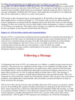
have a full mesh of PVCs. The configuration for this lab is shown in Figure 4−16. Most network protocols
assume transitivity. This means that if RouterB can communicate with RouterA and if RouterC can
159
communicate with RouterA, then RouterB can communicate with RouterC. This does not apply with Frame
Relay.
Figure 4−16: Full connectivity with partial PVC mesh
This issue poses a problem in configuring Frame Relay networks. As depicted in Figure 4−16, the
configuration has only two PVCs. A company purchasing PVCs from a Frame Relay provider would ideally
like to be able to communicate from RouterB to RouterC without having to purchase a third PVC between
RouterB and RouterC.
The four routers are connected as shown in Figure 4−16. Three of the routers are configured as Frame Relay
DTE devices. The fourth router is configured as a Frame Relay switch. The router configured as a Frame
Relay switch is also configured to supply clock to the DTE router. This is accomplished via the use of a Cisco
DCE cable and a clock rate statement in the router's configuration.
Note
Keep in mind that although a Cisco router can act as a Frame Relay switch, this feature is
typically only used in test and demonstration situations such as this lab.
Router Configuration
The initial configurations for the four routers in this example are as follows. Key Frame Relay commands are
highlighted in bold.
FrameSwitch (Frame Relay Switch)
Current configuration:
!
version 11.2
no service udp−small−servers
no service tcp−small−servers
!
hostname FrameSwitch
!
!
frame−relay switching ← Configure Frame Relay switching on this interface
!
interface Serial0/0
no ip address
encapsulation frame−relay
clockrate 64000 ← Clock the DTE at 64,000 bps
frame−relay lmi−type ansi ← Set the LMI type to Annex D
frame−relay intf−type dce ← Set the interface type to a DCE
frame−relay route 200 interface Serial0/1 200 ← Define a PVC between
interface S0/0 and S0/1
!
interface Serial0/1
no ip address
160
encapsulation frame−relay
clockrate 64000
frame−relay lmi−type ansi
frame−relay intf−type dce
frame−relay route 200 interface Serial0/0
frame−relay route 210 interface Serial1/0
!
interface Serial1/0
no ip address
encapsulation frame−relay
clockrate 64000
frame−relay lmi−type ansi
frame−relay intf−type dce
frame−relay route 210 interface Serial0/1
!
no ip classless
!
line con 0
line aux 0
line vty 0 4
login
!
end
200
210
210
RouterA (Frame Relay DTE)
Current configuration:
!
version 11.2
no service udp−small−servers
no service tcp−small−servers
!
hostname RouterA
!
interface Serial0/0
ip address 192.1.1.1 255.255.255.0
encapsulation frame−relay ← Set the interface encapsulation to Frame Relay
frame−relay lmi−type ansi ← Set the LMI type to Annex D
!
no ip classless
!
line con 0
line aux 0
line vty 0 4
login
!
end
RouterB (Frame Relay DTE)
Current configuration:
!
version 11.2
no service udp−small−servers
no service tcp−small−servers
!
hostname RouterB
!
interface Serial0/0
ip address 192.1.1.3 255.255.255.0
encapsulation frame−relay
frame−relay lmi−type ansi
!
no ip classless
!
line con 0
161
line aux 0
line vty 0 4
login
!
end
RouterC (Frame Relay DTE)
Current configuration:
!
version 11.2
no service password−encryption
no service udp−small−servers
no service tcp−small−servers
!
hostname RouterC
!
interface Serial0/0
ip address 192.1.1.4 255.255.255.0
encapsulation frame−relay
frame−relay lmi−type ansi
!
no ip classless
!
!
line con 0
line aux 0
line vty 0 4
login
!
end
Monitoring and Testing the Configuration
Let's begin by connecting to the router FrameSwitch and verifying that it is working properly. Issue the show
frame pvc command to display all DLCIs that are passing through the router. The PVC configuration is more
complex for this lab than for the previous labs. There are now two PVCs that are configured on this router.
Several items indicate that these ports are acting as Frame Relay switch ports. These include the DLCI usage
being referenced as switched, the interface being referred to as a Frame Relay DCE, and the indication of
Num Pkts Switched. The PVC status should indicate Active.
FrameSwitch#sh frame pvc
PVC Statistics for interface Serial0/0
(Frame Relay DCE)
DLCI = 200, DLCI USAGE = SWITCHED, PVC STATUS = ACTIVE, INTERFACE = Serial0/0
input pkts 16
output pkts 17
in bytes 1590
out bytes 1620
dropped pkts 0
in FECN pkts 0
in BECN pkts 0
out FECN pkts 0
out BECN pkts 0
in DE pkts 0
out DE pkts 0
pvc create time 00:47:35, last time pvc status changed 00:46:33
Num Pkts Switched 16
PVC Statistics for interface Serial0/1
(Frame Relay DCE)
DLCI = 200, DLCI USAGE = SWITCHED, PVC STATUS = ACTIVE, INTERFACE = Serial0/1
input pkts 17
output pkts 16
in bytes 1620
out bytes 1590
dropped pkts 0
in FECN pkts 0
in BECN pkts 0
out FECN pkts 0
out BECN pkts 0
in DE pkts 0
out DE pkts 0
pvc create time 00:46:41, last time pvc status changed 00:46:40
Num Pkts Switched 17
162
DLCI = 210, DLCI USAGE = SWITCHED, PVC STATUS = ACTIVE, INTERFACE = Serial0/1
input pkts 40
output pkts 36
in bytes 3790
out bytes 3670
dropped pkts 0
in FECN pkts 0
in BECN pkts 0
out FECN pkts 0
out BECN pkts 0
in DE pkts 0
out DE pkts 0
pvc create time 00:46:30, last time pvc status changed 00:15:12
Num Pkts Switched 40
PVC Statistics for interface Serial1/0
(Frame Relay DCE)
DLCI = 210, DLCI USAGE = SWITCHED, PVC STATUS = ACTIVE, INTERFACE = Serial1/0
input pkts 36
output pkts 40
in bytes 3670
out bytes 3790
dropped pkts 0
in FECN pkts 0
in BECN pkts 0
out FECN pkts 0
out BECN pkts 0
in DE pkts 0
out DE pkts 0
pvc create time 00:47:07, last time pvc status changed 00:46:24
Num Pkts Switched 36
Next issue the show frame route command. This command will display all active PVCs that are defined on
the router. Four DLCIs are configured on this router. RouterA is acting as a hub router. All DLCIs terminate
on this router. RouterB and RouterC are acting as spoke routers, each having a PVC terminating on RouterA.
FrameSwitch#sh
Input Intf
Serial0/0
Serial0/1
Serial0/1
Serial1/0
frame route
Input Dlci
200
200
210
210
Output Intf
Serial0/1
Serial0/0
Serial1/0
Serial0/1
Output Dlci
200
200
210
210
Status
active
active
active
active
The show interface command will display the status of the serial interfaces on the router. Several important
Frame Relay parameters displayed by this command are highlighted in bold, including the interface
encapsulation (Frame−Relay), the LMI status (LMI up), the fact that this port is acting as a Frame Relay DCE,
the LMI signaling type (ANSI Annex D), and the LMI exchange counters.
FrameSwitch#sh int s 0/0
Serial0/0 is up, line protocol is up
Hardware is QUICC Serial
MTU 1500 bytes, BW 1544 Kbit, DLY 20000 usec, rely 255/255, load 1/255
Encapsulation FRAME−RELAY, loopback not set, keepalive set (10 sec)
LMI enq sent 0, LMI stat recvd 0, LMI upd recvd 0
LMI enq recvd 297, LMI stat sent 297, LMI upd sent 0, DCE LMI up
LMI DLCI 0 LMI type is ANSI Annex D frame relay DCE
.
.
Let's start by connecting to RouterC. Type the show frame map command to display the current Frame Relay
map.
RouterC#sh frame map
Serial0/0 (up): ip 192.1.1.1 dlci 210(0xD2,0x3420), dynamic,
broadcast,, status defined, active
We see that RouterC has resolved the IP address of RouterA (192.1.1.1) via inverse ARP. Notice that RouterC
has not resolved the address of RouterB. This is because RouterC has a PVC only to RouterA, not to RouterB.
In general, a spoke router (such as RouterC) will inverse ARP to the hub router (such as RouterA) but will not
inverse ARP to other spoke routers.
Verify that you can ping from RouterC to RouterA:
RouterC#ping 192.1.1.1
163
Type escape sequence to abort.
Sending 5, 100−byte ICMP Echos to 192.1.1.1, timeout is 2 seconds:
!!!!!
Success rate is 100 percent (5/5), round−trip min/avg/max = 56/56/56 ms
Verify that DLCI 210 is active on interface s0/0 of RouterC:
RouterC#sh frame pvc
PVC Statistics for interface Serial0/0 (Frame Relay DTE)
DLCI = 210, DLCI USAGE = LOCAL, PVC STATUS = ACTIVE, INTERFACE = Serial0/0
input pkts 33
output pkts 31
in bytes 3210
out bytes 3150
dropped pkts 2
in FECN pkts 0
in BECN pkts 0
out FECN pkts 0
out BECN pkts 0
in DE pkts 0
out DE pkts 0
out bcast pkts 1
out bcast bytes 30
pvc create time 00:10:44, last time pvc status changed 00:09:44
Now let's connect to RouterB. The show frame map command will verify that RouterB has resolved the IP
address of RouterA via inverse ARP. Again, notice that RouterB does not have a mapping to RouterC.
RouterB#sh frame map
Serial0/0 (up): ip 192.1.1.1 dlci 200(0xC8,0x3080), dynamic,
broadcast,, status defined, active
Verify that you can ping RouterA from RouterB:
RouterB#ping 192.1.1.1
Type escape sequence to abort.
Sending 5, 100−byte ICMP Echos to 192.1.1.1, timeout is 2 seconds:
!!!!!
Success rate is 100 percent (5/5), round−trip min/avg/max = 56/56/60 ms
Verify that DLCI 200 is active on interface s0/0 of RouterB:
RouterB#sh frame pvc
PVC Statistics for interface Serial0/0 (Frame Relay DTE)
DLCI = 200, DLCI USAGE = LOCAL, PVC STATUS = ACTIVE, INTERFACE = Serial0/0
input pkts 12
output pkts 11
in bytes 1100
out bytes 1070
dropped pkts 1
in FECN pkts 0
in BECN pkts 0
out FECN pkts 0
out BECN pkts 0
in DE pkts 0
out DE pkts 0
pvc create time 00:43:35, last time pvc status changed 00:42:35
Now connect to RouterA. The show frame pvc command should report two DLCIs coming into RouterA,
both assigned to interface s0/0. As we can see from Figure 4−16, one of these DLCIs connects RouterA to
RouterB ( DLCI 200) and the second DLCI connects RouterA to RouterC (DLCI 210).
RouterA#sh frame pvc
PVC Statistics for interface Serial0/0 (Frame Relay DTE)
DLCI = 200, DLCI USAGE = LOCAL, PVC STATUS = ACTIVE, INTERFACE = Serial0/0
input pkts 16
output pkts 16
in bytes 1590
out bytes 1590
dropped pkts 0
in FECN pkts 0
in BECN pkts 0
out FECN pkts 0
out BECN pkts 0
in DE pkts 0
out DE pkts 0
pvc create time 00:44:41, last time pvc status changed 00:44:41
164
DLCI = 210, DLCI USAGE = LOCAL, PVC STATUS = ACTIVE, INTERFACE = Serial0/0
input pkts 36
output pkts 39
in bytes 3670
out bytes 3760
dropped pkts 0
in FECN pkts 0
in BECN pkts 0
out FECN pkts 0
out BECN pkts 0
in DE pkts 0
out DE pkts 0
pvc create time 00:44:32, last time pvc status changed 00:13:12
The show frame map command will reveal that RouterA has resolved both of its DLCIs to a far−end IP
address. DLCI 200 has been resolved to 192.1.1.3 (RouterB) and DLCI 210 has been resolved to 192.1.1.4
(RouterC).
RouterA#sh fra map
Serial0/0 (up): ip 192.1.1.3 dlci 200(0xC8,0x3080), dynamic,
broadcast,, status defined, active
Serial0/0 (up): ip 192.1.1.4 dlci 210(0xD2,0x3420), dynamic,
broadcast,, status defined, active
Verify that you can reach both RouterB and RouterC with the ping command:
RouterA#ping 192.1.1.3
Type escape sequence to abort.
Sending 5, 100−byte ICMP Echos to 192.1.1.3, timeout is 2 seconds:
!!!!!
Success rate is 100 percent (5/5), round−trip min/avg/max = 56/57/60 ms
RouterA#ping 192.1.1.4
Type escape sequence to abort.
Sending 5, 100−byte ICMP Echos to 192.1.1.4, timeout is 2 seconds:
!!!!!
Success rate is 100 percent (5/5), round−trip min/avg/max = 56/56/60 ms
Now let's reconnect to RouterC. Verify that RouterC still has a Frame Relay map to RouterA with the show
frame map command.
RouterC#sh frame map
Serial0/0 (up): ip 192.1.1.1 dlci 210(0xD2,0x3420), dynamic,
broadcast,, status defined, active
Enable Frame Relay packet debugging with the debug frame packet command.
RouterC#debug frame packet
Frame Relay packet debugging is on
Verify that our hub router (RouterA) is still reachable at IP address 192.1.1.1.
RouterC#ping 192.1.1.1
Type escape sequence to abort.
Sending 5, 100−byte ICMP Echos to 192.1.1.1, timeout is 2 seconds:
!!!!!
Success rate is 100 percent (5/5), round−trip min/avg/max = 56/57/60 ms
The ping should be successful. The following screen print shows what the output from the debug frame
packet command will look like. Notice that the outgoing pings are sent on DLCI 210. The incoming
responses also come in on DLCI 210. RouterC knows how to reach RouterA because it has a Frame Relay
map entry to RouterA. Notice that there are five outgoing packets and five incoming packets.
Serial0/0(o): dlci 210(0x3421), pkt type 0x800(IP), datagramsize 104
Serial0/0(i): dlci 210(0x3421), pkt type 0x800, datagramsize 104
Serial0/0(o): dlci 210(0x3421), pkt type 0x800(IP), datagramsize 104
165
Serial0/0(i):
Serial0/0(o):
Serial0/0(i):
Serial0/0(o):
Serial0/0(i):
Serial0/0(o):
Serial0/0(i):
dlci
dlci
dlci
dlci
dlci
dlci
dlci
210(0x3421),
210(0x3421),
210(0x3421),
210(0x3421),
210(0x3421),
210(0x3421),
210(0x3421),
pkt
pkt
pkt
pkt
pkt
pkt
pkt
type
type
type
type
type
type
type
0x800, datagramsize 104
0x800(IP), datagramsize 104
0x800, datagramsize 104
0x800(IP), datagramsize 104
0x800, datagramsize 104
0x800(IP), datagramsize 104
0x800, datagramsize 104
Now let's try to ping RouterB at IP address 192.1.1.3.
RouterC#ping 192.1.1.3
Type escape sequence to abort.
Sending 5, 100−byte ICMP Echos to 192.1.1.3, timeout is 2 seconds:
Serial0/0:Encaps failed−−no map
Serial0/0:Encaps failed−−no map
Serial0/0:Encaps failed−−no map
Serial0/0:Encaps failed−−no map
Serial0/0:Encaps failed−−no map
Success rate is 0 percent (0/5)
entry
entry
entry
entry
entry
link
link
link
link
link
7(IP).
7(IP).
7(IP).
7(IP).
7(IP).
The ping failed. The output of the debug frame packet shows that RouterC does not know how to
encapsulate the ping that is destined for RouterB. This is caused by RouterC not having a Frame Relay
mapping to RouterB.
The solution is to tell RouterC how to get to RouterB with a Frame Relay map statement. Enter configuration
mode and enter the command frame−relay map ip 192.1.1.3 210 under interface s 0/0. This will tell RouterC
that if it has traffic for RouterB it should send that traffic out on DLCI 210. This will be enough to get the
traffic to RouterA. RouterA then has its own Frame Relay map to RouterB, so the traffic will be able to find
its destination.
RouterC#config term
Enter configuration commands, one per line. End with CNTL/Z.
RouterC(config)#int s 0/0
RouterC(config−if)#frame−relay map ip 192.1.1.3 210
RouterC(config−if)#exit
RouterC(config)#exit
Verify that the new Frame Relay map has taken effect by typing the show frame map command. Notice how
the map to RouterA is dynamic while the map to RouterB is static. This is because the map to RouterA
(192.1.1.1) was discovered via inverse ARP while the map to RouterB (192.1.1.3) was manually entered into
the RouterC's configuration.
RouterC#sh frame map
Serial0/0 (up): ip 192.1.1.1 dlci 210(0xD2,0x3420), dynamic,
broadcast,, status defined, active
Serial0/0 (up): ip 192.1.1.3 dlci 210(0xD2,0x3420), static,
CISCO, status defined, active
Now try to ping RouterB at IP address 192.1.1.3.
RouterC#ping 192.1.1.3
Type escape sequence to abort.
Sending 5, 100−byte ICMP Echos to 192.1.1.3, timeout is 2 seconds:
Serial0/0(o): dlci 210(0x3421),
Serial0/0(o): dlci 210(0x3421),
Serial0/0(o): dlci 210(0x3421),
Serial0/0(o): dlci 210(0x3421),
Serial0/0(o): dlci 210(0x3421),
Success rate is 0 percent (0/5)
pkt
pkt
pkt
pkt
pkt
type
type
type
type
type
0x800(IP),
0x800(IP),
0x800(IP),
0x800(IP),
0x800(IP),
166
datagramsize
datagramsize
datagramsize
datagramsize
datagramsize
104
104.
104.
104.
104.
Notice that the ping still fails. The output from the debug command is now different from the first time we
tried to ping 192.1.1.3. The first time we tried the ping, we had not added a static Frame Relay map to
192.1.1.3 and the debug output showed encapsulation failures. Now the debug shows that the router knows to
encapsulate the ICMP packets in DLCI 210. Why, then, does the ping fail? The ping fails because when the
ping traffic gets to RouterB, RouterB does not have a path back to RouterC. We must now go to RouterB and
add an equivalent Frame Relay map statement.
Connect to RouterB and display the current Frame Relay map with the show frame map command. Verify
that only a single dynamic map exists to RouterA at IP address 192.1.1.1.
RouterB#sh frame map
Serial0/0 (up): ip 192.1.1.1 dlci 200(0xC8,0x3080), dynamic,
broadcast,, status defined, active
Enter configuration mode and add the statement frame−relay map IP 192.1.1.4 200 under interface s 0/0.
This will tell RouterB that if it has traffic for 192.1.1.4 (RouterC), it should then send the traffic out on DLCI
200. Encapsulating the traffic on DLCI 200 will send it to RouterA. RouterA then has a Frame Relay map to
RouterC and will know how to get the traffic there.
RouterB#config term
Enter configuration commands, one per line. End with CNTL/Z.
RouterB(config)#int s 0/0
RouterB(config−if)#frame−relay map ip 192.1.1.4 200
RouterB(config−if)#exit
RouterB(config)#exit
Verify that there are now two Frame Relay maps for RouterB. The first map, to RouterA (192.1.1.1), is a
dynamic map because it was discovered via inverse ARP. The second map, to RouterC, is a static map
because it was manually entered in the router's configuration.
RouterB#sh frame map
Serial0/0 (up): ip 192.1.1.1 dlci 200(0xC8,0x3080), dynamic,
broadcast,, status defined, active
Serial0/0 (up): ip 192.1.1.4 dlci 200(0xC8,0x3080), static,
CISCO, status defined, active
You should now be able to successfully ping RouterC (at IP address 192.1.1.4) from RouterB.
RouterB#ping 192.1.1.4
Type escape sequence to abort.
Sending 5, 100−byte ICMP Echos to 192.1.1.4, timeout is 2 seconds:
!!!!!
Success rate is 100 percent (5/5), round−trip min/avg/max = 112/113/120 ms
Lab #16: Full Connectivity witha Partial PVC Mesh and
FrameRelay Map Statements
Equipment Needed
The following equipment is needed to perform this lab exercise:
• Four Cisco routers, three of which must have at least one serial port, and one of which must have
three serial ports
• Cisco IOS 11.2 or higher
• A PC running a terminal emulation program for console port connection to the routers
167
• Three Cisco DTE/DCE crossover cables. If no crossover cables are available, you can make a
crossover cable by connecting a standard Cisco DTE cable to a standard Cisco DCE cable
Note
The DCE side of the V.35 crossover cables must be connected to the router
FrameSwitch.
Configuration Overview
This configuration will demonstrate a method of achieving full mesh connectivity in a network that does not
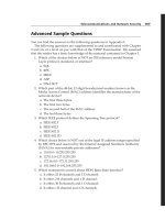
have a full mesh of PVCs. The configuration for this lab is shown in Figure 4−16. Most network protocols
assume transitivity. This means that if RouterB can communicate with RouterA and if RouterC can
communicate with RouterA, then RouterB can communicate with RouterC. This does not apply with Frame
Relay.
Figure 4−16: Full connectivity with partial PVC mesh
This issue poses a problem in configuring Frame Relay networks. As depicted in Figure 4−16, the
configuration has only two PVCs. A company purchasing PVCs from a Frame Relay provider would ideally
like to be able to communicate from RouterB to RouterC without having to purchase a third PVC between
RouterB and RouterC.
The four routers are connected as shown in Figure 4−16. Three of the routers are configured as Frame Relay
DTE devices. The fourth router is configured as a Frame Relay switch. The router configured as a Frame
Relay switch is also configured to supply clock to the DTE router. This is accomplished via the use of a Cisco
DCE cable and a clock rate statement in the router's configuration.
Note
Keep in mind that although a Cisco router can act as a Frame Relay switch, this feature is
typically only used in test and demonstration situations such as this lab.
Router Configuration
The initial configurations for the four routers in this example are as follows. Key Frame Relay commands are
highlighted in bold.
FrameSwitch (Frame Relay Switch)
Current configuration:
!
version 11.2
no service udp−small−servers
no service tcp−small−servers
!
hostname FrameSwitch
!
168
!
frame−relay switching ← Configure Frame Relay switching on this interface
!
interface Serial0/0
no ip address
encapsulation frame−relay
clockrate 64000 ← Clock the DTE at 64,000 bps
frame−relay lmi−type ansi ← Set the LMI type to Annex D
frame−relay intf−type dce ← Set the interface type to a DCE
frame−relay route 200 interface Serial0/1 200 ← Define a PVC between
interface S0/0 and S0/1
!
interface Serial0/1
no ip address
encapsulation frame−relay
clockrate 64000
frame−relay lmi−type ansi
frame−relay intf−type dce
frame−relay route 200 interface Serial0/0 200
frame−relay route 210 interface Serial1/0 210
!
interface Serial1/0
no ip address
encapsulation frame−relay
clockrate 64000
frame−relay lmi−type ansi
frame−relay intf−type dce
frame−relay route 210 interface Serial0/1 210
!
no ip classless
!
line con 0
line aux 0
line vty 0 4
login
!
end
RouterA (Frame Relay DTE)
Current configuration:
!
version 11.2
no service udp−small−servers
no service tcp−small−servers
!
hostname RouterA
!
interface Serial0/0
ip address 192.1.1.1 255.255.255.0
encapsulation frame−relay ← Set the interface encapsulation to Frame Relay
frame−relay lmi−type ansi ← Set the LMI type to Annex D
!
no ip classless
!
line con 0
line aux 0
line vty 0 4
login
!
end
RouterB (Frame Relay DTE)
Current configuration:
!
169
version 11.2
no service udp−small−servers
no service tcp−small−servers
!
hostname RouterB
!
interface Serial0/0
ip address 192.1.1.3 255.255.255.0
encapsulation frame−relay
frame−relay lmi−type ansi
!
no ip classless
!
line con 0
line aux 0
line vty 0 4
login
!
end
RouterC (Frame Relay DTE)
Current configuration:
!
version 11.2
no service password−encryption
no service udp−small−servers
no service tcp−small−servers
!
hostname RouterC
!
interface Serial0/0
ip address 192.1.1.4 255.255.255.0
encapsulation frame−relay
frame−relay lmi−type ansi
!
no ip classless
!
!
line con 0
line aux 0
line vty 0 4
login
!
end
Monitoring and Testing the Configuration
Let's begin by connecting to the router FrameSwitch and verifying that it is working properly. Issue the show
frame pvc command to display all DLCIs that are passing through the router. The PVC configuration is more
complex for this lab than for the previous labs. There are now two PVCs that are configured on this router.
Several items indicate that these ports are acting as Frame Relay switch ports. These include the DLCI usage
being referenced as switched, the interface being referred to as a Frame Relay DCE, and the indication of
Num Pkts Switched. The PVC status should indicate Active.
FrameSwitch#sh frame pvc
PVC Statistics for interface Serial0/0
(Frame Relay DCE)
DLCI = 200, DLCI USAGE = SWITCHED, PVC STATUS = ACTIVE, INTERFACE = Serial0/0
input pkts 16
out bytes 1620
in BECN pkts 0
in DE pkts 0
output pkts 17
dropped pkts 0
out FECN pkts 0
out DE pkts 0
in bytes 1590
in FECN pkts 0
out BECN pkts 0
170
pvc create time 00:47:35, last time pvc status changed 00:46:33
Num Pkts Switched 16
PVC Statistics for interface Serial0/1
(Frame Relay DCE)
DLCI = 200, DLCI USAGE = SWITCHED, PVC STATUS = ACTIVE, INTERFACE = Serial0/1
input pkts 17
output pkts 16
in bytes 1620
out bytes 1590
dropped pkts 0
in FECN pkts 0
in BECN pkts 0
out FECN pkts 0
out BECN pkts 0
in DE pkts 0
out DE pkts 0
pvc create time 00:46:41, last time pvc status changed 00:46:40
Num Pkts Switched 17
DLCI = 210, DLCI USAGE = SWITCHED, PVC STATUS = ACTIVE, INTERFACE = Serial0/1
input pkts 40
output pkts 36
in bytes 3790
out bytes 3670
dropped pkts 0
in FECN pkts 0
in BECN pkts 0
out FECN pkts 0
out BECN pkts 0
in DE pkts 0
out DE pkts 0
pvc create time 00:46:30, last time pvc status changed 00:15:12
Num Pkts Switched 40
PVC Statistics for interface Serial1/0
(Frame Relay DCE)
DLCI = 210, DLCI USAGE = SWITCHED, PVC STATUS = ACTIVE, INTERFACE = Serial1/0
input pkts 36
output pkts 40
in bytes 3670
out bytes 3790
dropped pkts 0
in FECN pkts 0
in BECN pkts 0
out FECN pkts 0
out BECN pkts 0
in DE pkts 0
out DE pkts 0
pvc create time 00:47:07, last time pvc status changed 00:46:24
Num Pkts Switched 36
Next issue the show frame route command. This command will display all active PVCs that are defined on
the router. Four DLCIs are configured on this router. RouterA is acting as a hub router. All DLCIs terminate
on this router. RouterB and RouterC are acting as spoke routers, each having a PVC terminating on RouterA.
FrameSwitch#sh
Input Intf
Serial0/0
Serial0/1
Serial0/1
Serial1/0
frame route
Input Dlci
200
200
210
210
Output Intf
Serial0/1
Serial0/0
Serial1/0
Serial0/1
Output Dlci
200
200
210
210
Status
active
active
active
active
The show interface command will display the status of the serial interfaces on the router. Several important
Frame Relay parameters displayed by this command are highlighted in bold, including the interface
encapsulation (Frame−Relay), the LMI status (LMI up), the fact that this port is acting as a Frame Relay DCE,
the LMI signaling type (ANSI Annex D), and the LMI exchange counters.
FrameSwitch#sh int s 0/0
Serial0/0 is up, line protocol is up
Hardware is QUICC Serial
MTU 1500 bytes, BW 1544 Kbit, DLY 20000 usec, rely 255/255, load 1/255
Encapsulation FRAME−RELAY, loopback not set, keepalive set (10 sec)
LMI enq sent 0, LMI stat recvd 0, LMI upd recvd 0
LMI enq recvd 297, LMI stat sent 297, LMI upd sent 0, DCE LMI up
LMI DLCI 0 LMI type is ANSI Annex D frame relay DCE
.
.
Let's start by connecting to RouterC. Type the show frame map command to display the current Frame Relay
map.
RouterC#sh frame map
171
Serial0/0 (up): ip 192.1.1.1 dlci 210(0xD2,0x3420), dynamic,
broadcast,, status defined, active
We see that RouterC has resolved the IP address of RouterA (192.1.1.1) via inverse ARP. Notice that RouterC
has not resolved the address of RouterB. This is because RouterC has a PVC only to RouterA, not to RouterB.
In general, a spoke router (such as RouterC) will inverse ARP to the hub router (such as RouterA) but will not
inverse ARP to other spoke routers.
Verify that you can ping from RouterC to RouterA:
RouterC#ping 192.1.1.1
Type escape sequence to abort.
Sending 5, 100−byte ICMP Echos to 192.1.1.1, timeout is 2 seconds:
!!!!!
Success rate is 100 percent (5/5), round−trip min/avg/max = 56/56/56 ms
Verify that DLCI 210 is active on interface s0/0 of RouterC:
RouterC#sh frame pvc
PVC Statistics for interface Serial0/0 (Frame Relay DTE)
DLCI = 210, DLCI USAGE = LOCAL, PVC STATUS = ACTIVE, INTERFACE = Serial0/0
input pkts 33
output pkts 31
in bytes 3210
out bytes 3150
dropped pkts 2
in FECN pkts 0
in BECN pkts 0
out FECN pkts 0
out BECN pkts 0
in DE pkts 0
out DE pkts 0
out bcast pkts 1
out bcast bytes 30
pvc create time 00:10:44, last time pvc status changed 00:09:44
Now let's connect to RouterB. The show frame map command will verify that RouterB has resolved the IP
address of RouterA via inverse ARP. Again, notice that RouterB does not have a mapping to RouterC.
RouterB#sh frame map
Serial0/0 (up): ip 192.1.1.1 dlci 200(0xC8,0x3080), dynamic,
broadcast,, status defined, active
Verify that you can ping RouterA from RouterB:
RouterB#ping 192.1.1.1
Type escape sequence to abort.
Sending 5, 100−byte ICMP Echos to 192.1.1.1, timeout is 2 seconds:
!!!!!
Success rate is 100 percent (5/5), round−trip min/avg/max = 56/56/60 ms
Verify that DLCI 200 is active on interface s0/0 of RouterB:
RouterB#sh frame pvc
PVC Statistics for interface Serial0/0 (Frame Relay DTE)
DLCI = 200, DLCI USAGE = LOCAL, PVC STATUS = ACTIVE, INTERFACE = Serial0/0
input pkts 12
output pkts 11
in bytes 1100
out bytes 1070
dropped pkts 1
in FECN pkts 0
in BECN pkts 0
out FECN pkts 0
out BECN pkts 0
in DE pkts 0
out DE pkts 0
pvc create time 00:43:35, last time pvc status changed 00:42:35
Now connect to RouterA. The show frame pvc command should report two DLCIs coming into RouterA,
both assigned to interface s0/0. As we can see from Figure 4−16, one of these DLCIs connects RouterA to
172
RouterB ( DLCI 200) and the second DLCI connects RouterA to RouterC (DLCI 210).
RouterA#sh frame pvc
PVC Statistics for interface Serial0/0 (Frame Relay DTE)
DLCI = 200, DLCI USAGE = LOCAL, PVC STATUS = ACTIVE, INTERFACE = Serial0/0
input pkts 16
output pkts 16
in bytes 1590
out bytes 1590
dropped pkts 0
in FECN pkts 0
in BECN pkts 0
out FECN pkts 0
out BECN pkts 0
in DE pkts 0
out DE pkts 0
pvc create time 00:44:41, last time pvc status changed 00:44:41
DLCI = 210, DLCI USAGE = LOCAL, PVC STATUS = ACTIVE, INTERFACE = Serial0/0
input pkts 36
output pkts 39
in bytes 3670
out bytes 3760
dropped pkts 0
in FECN pkts 0
in BECN pkts 0
out FECN pkts 0
out BECN pkts 0
in DE pkts 0
out DE pkts 0
pvc create time 00:44:32, last time pvc status changed 00:13:12
The show frame map command will reveal that RouterA has resolved both of its DLCIs to a far−end IP
address. DLCI 200 has been resolved to 192.1.1.3 (RouterB) and DLCI 210 has been resolved to 192.1.1.4
(RouterC).
RouterA#sh fra map
Serial0/0 (up): ip 192.1.1.3 dlci 200(0xC8,0x3080), dynamic,
broadcast,, status defined, active
Serial0/0 (up): ip 192.1.1.4 dlci 210(0xD2,0x3420), dynamic,
broadcast,, status defined, active
Verify that you can reach both RouterB and RouterC with the ping command:
RouterA#ping 192.1.1.3
Type escape sequence to abort.
Sending 5, 100−byte ICMP Echos to 192.1.1.3, timeout is 2 seconds:
!!!!!
Success rate is 100 percent (5/5), round−trip min/avg/max = 56/57/60 ms
RouterA#ping 192.1.1.4
Type escape sequence to abort.
Sending 5, 100−byte ICMP Echos to 192.1.1.4, timeout is 2 seconds:
!!!!!
Success rate is 100 percent (5/5), round−trip min/avg/max = 56/56/60 ms
Now let's reconnect to RouterC. Verify that RouterC still has a Frame Relay map to RouterA with the show
frame map command.
RouterC#sh frame map
Serial0/0 (up): ip 192.1.1.1 dlci 210(0xD2,0x3420), dynamic,
broadcast,, status defined, active
Enable Frame Relay packet debugging with the debug frame packet command.
RouterC#debug frame packet
Frame Relay packet debugging is on
Verify that our hub router (RouterA) is still reachable at IP address 192.1.1.1.
RouterC#ping 192.1.1.1
Type escape sequence to abort.
173
Sending 5, 100−byte ICMP Echos to 192.1.1.1, timeout is 2 seconds:
!!!!!
Success rate is 100 percent (5/5), round−trip min/avg/max = 56/57/60 ms
The ping should be successful. The following screen print shows what the output from the debug frame
packet command will look like. Notice that the outgoing pings are sent on DLCI 210. The incoming
responses also come in on DLCI 210. RouterC knows how to reach RouterA because it has a Frame Relay
map entry to RouterA. Notice that there are five outgoing packets and five incoming packets.
Serial0/0(o):
Serial0/0(i):
Serial0/0(o):
Serial0/0(i):
Serial0/0(o):
Serial0/0(i):
Serial0/0(o):
Serial0/0(i):
Serial0/0(o):
Serial0/0(i):
dlci
dlci
dlci
dlci
dlci
dlci
dlci
dlci
dlci
dlci
210(0x3421),
210(0x3421),
210(0x3421),
210(0x3421),
210(0x3421),
210(0x3421),
210(0x3421),
210(0x3421),
210(0x3421),
210(0x3421),
pkt
pkt
pkt
pkt
pkt
pkt
pkt
pkt
pkt
pkt
type
type
type
type
type
type
type
type
type
type
0x800(IP), datagramsize
0x800, datagramsize 104
0x800(IP), datagramsize
0x800, datagramsize 104
0x800(IP), datagramsize
0x800, datagramsize 104
0x800(IP), datagramsize
0x800, datagramsize 104
0x800(IP), datagramsize
0x800, datagramsize 104
104
104
104
104
104
Now let's try to ping RouterB at IP address 192.1.1.3.
RouterC#ping 192.1.1.3
Type escape sequence to abort.
Sending 5, 100−byte ICMP Echos to 192.1.1.3, timeout is 2 seconds:
Serial0/0:Encaps failed−−no map
Serial0/0:Encaps failed−−no map
Serial0/0:Encaps failed−−no map
Serial0/0:Encaps failed−−no map
Serial0/0:Encaps failed−−no map
Success rate is 0 percent (0/5)
entry
entry
entry
entry
entry
link
link
link
link
link
7(IP).
7(IP).
7(IP).
7(IP).
7(IP).
The ping failed. The output of the debug frame packet shows that RouterC does not know how to
encapsulate the ping that is destined for RouterB. This is caused by RouterC not having a Frame Relay
mapping to RouterB.
The solution is to tell RouterC how to get to RouterB with a Frame Relay map statement. Enter configuration
mode and enter the command frame−relay map ip 192.1.1.3 210 under interface s 0/0. This will tell RouterC
that if it has traffic for RouterB it should send that traffic out on DLCI 210. This will be enough to get the
traffic to RouterA. RouterA then has its own Frame Relay map to RouterB, so the traffic will be able to find
its destination.
RouterC#config term
Enter configuration commands, one per line. End with CNTL/Z.
RouterC(config)#int s 0/0
RouterC(config−if)#frame−relay map ip 192.1.1.3 210
RouterC(config−if)#exit
RouterC(config)#exit
Verify that the new Frame Relay map has taken effect by typing the show frame map command. Notice how
the map to RouterA is dynamic while the map to RouterB is static. This is because the map to RouterA
(192.1.1.1) was discovered via inverse ARP while the map to RouterB (192.1.1.3) was manually entered into
the RouterC's configuration.
RouterC#sh frame map
Serial0/0 (up): ip 192.1.1.1 dlci 210(0xD2,0x3420), dynamic,
broadcast,, status defined, active
Serial0/0 (up): ip 192.1.1.3 dlci 210(0xD2,0x3420), static,
CISCO, status defined, active
174
Now try to ping RouterB at IP address 192.1.1.3.
RouterC#ping 192.1.1.3
Type escape sequence to abort.
Sending 5, 100−byte ICMP Echos to 192.1.1.3, timeout is 2 seconds:
Serial0/0(o): dlci 210(0x3421),
Serial0/0(o): dlci 210(0x3421),
Serial0/0(o): dlci 210(0x3421),
Serial0/0(o): dlci 210(0x3421),
Serial0/0(o): dlci 210(0x3421),
Success rate is 0 percent (0/5)
pkt
pkt
pkt
pkt
pkt
type
type
type
type
type
0x800(IP),
0x800(IP),
0x800(IP),
0x800(IP),
0x800(IP),
datagramsize
datagramsize
datagramsize
datagramsize
datagramsize
104
104.
104.
104.
104.
Notice that the ping still fails. The output from the debug command is now different from the first time we
tried to ping 192.1.1.3. The first time we tried the ping, we had not added a static Frame Relay map to
192.1.1.3 and the debug output showed encapsulation failures. Now the debug shows that the router knows to
encapsulate the ICMP packets in DLCI 210. Why, then, does the ping fail? The ping fails because when the
ping traffic gets to RouterB, RouterB does not have a path back to RouterC. We must now go to RouterB and
add an equivalent Frame Relay map statement.
Connect to RouterB and display the current Frame Relay map with the show frame map command. Verify
that only a single dynamic map exists to RouterA at IP address 192.1.1.1.
RouterB#sh frame map
Serial0/0 (up): ip 192.1.1.1 dlci 200(0xC8,0x3080), dynamic,
broadcast,, status defined, active
Enter configuration mode and add the statement frame−relay map IP 192.1.1.4 200 under interface s 0/0.
This will tell RouterB that if it has traffic for 192.1.1.4 (RouterC), it should then send the traffic out on DLCI
200. Encapsulating the traffic on DLCI 200 will send it to RouterA. RouterA then has a Frame Relay map to
RouterC and will know how to get the traffic there.
RouterB#config term
Enter configuration commands, one per line. End with CNTL/Z.
RouterB(config)#int s 0/0
RouterB(config−if)#frame−relay map ip 192.1.1.4 200
RouterB(config−if)#exit
RouterB(config)#exit
Verify that there are now two Frame Relay maps for RouterB. The first map, to RouterA (192.1.1.1), is a
dynamic map because it was discovered via inverse ARP. The second map, to RouterC, is a static map
because it was manually entered in the router's configuration.
RouterB#sh frame map
Serial0/0 (up): ip 192.1.1.1 dlci 200(0xC8,0x3080), dynamic,
broadcast,, status defined, active
Serial0/0 (up): ip 192.1.1.4 dlci 200(0xC8,0x3080), static,
CISCO, status defined, active
You should now be able to successfully ping RouterC (at IP address 192.1.1.4) from RouterB.
RouterB#ping 192.1.1.4
Type escape sequence to abort.
Sending 5, 100−byte ICMP Echos to 192.1.1.4, timeout is 2 seconds:
!!!!!
Success rate is 100 percent (5/5), round−trip min/avg/max = 112/113/120 ms
175