artech house a professionals guide to data communication in a tcp ip world 2004 phần 2 ppsx
Bạn đang xem bản rút gọn của tài liệu. Xem và tải ngay bản đầy đủ của tài liệu tại đây (403.99 KB, 27 trang )
extreme cases, it may command the sender to stop sending until the congestion
clears.
Changing traffic loads from other senders may affect some of the intermediate
nodes. They pass congestion status information along to the receiver. In addition,
the sender may send special packets to probe conditions along the path. The receiver
returns these packets to the sender. On the basis of this information, the sender may
reduce the transmission unit size so that the intermediate nodes can make buffer
capacity available to other circuits. In other situations, the intermediate nodes may
destroy packets that have been sent in excess of the rate that the network owner has
guaranteed to the user. Flow control requires constant monitoring by all the nodes in
the network and frequent instructions to the senders to slow down or speed up to
accommodate changing conditions.
1.4.10 Retransmission Time-Out
In TCP, all segments containing data must be acknowledged. For each connection,
TCP maintains a variable whose value is the amount of time within which an ACK is
expected for the segment just sent. Called the retransmission time-out (RTO), if the
sender does not receive an ACK by the time RTO expires, the segment is retransmit
-
ted. To prevent needless repetitions, RTO must be greater than the round-trip time
(RTT) for the connection. Since the RTT is likely to vary with traffic conditions, it
must be monitored continually, and the RTO adjusted accordingly.
For frames containing data, TCP uses an exponential backoff algorithm to
determine the RTO of successive retransmissions. Initially, when the TCP segment is
sent, the RTO is set to the value currently known for the connection (RTO1). If the
retransmission timer expires without an acknowledgment, the segment is resent and
the RTO timer is set to 2
n
RTO1 (where n = 0, 1, 2, …). This step is repeated until a
maximum number of retransmissions are reached. At that time the connection is
abandoned.
Segments that contain no data (e.g., ACKs) are not acknowledged. The sender
does not set an RTO for a data-less segment. Thus, it does not retransmit lost data-
less segments. To recover a lost ACK, the sender retransmits the segment(s) that the
ACK would have acknowledged. When assembling the data stream on the basis of
their sequence numbers, the receiver discards duplicate packets.
1.5 Creating a Connection
TCP employs a duplex logical circuit to implement communication between applica
-
tion processes running on two hosts. Each endpoint is identified by the combination
of host IP address and TCP port number. The circuit is identified by the endpoints in
each host (i.e., IP address 1 + TCP port 1, and IP address 2 + TCP port 2).
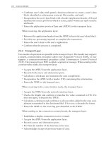
To create a connection, the hosts must exchange information and negotiate
parameters. The three steps involved are shown in Figure 1.4. The hosts:
•
Must learn the number of the first byte of data that will be sent to them. With
it they can locate each field and send acknowledgments using numbers recog
-
12 A TCP/IP World?
TLFeBOOK
nized by the sender. To achieve this, each must provide the other with its ini-
tial sequence number (ISN).
•
Must determine the size of the buffer memory the other will provide for the
receipt of their PDUs so that they do not send too much data at a time (and
lose it).
•
Must negotiate the maximum size of the segments they exchange so that com
-
munication will be as intense as possible.
•
May negotiate options to satisfy specialized objectives.
1.5.1 OPEN Function Calls
To create a connection, the sending application issues an active OPEN function call
that opens a message queue (port) from the application to the transport layer. Using
the fields in the TCP header, the source and destination port numbers are entered.
The initial sequence number for Host 1 (ISN1) is placed in the sequence number
field. The number 0 (because there is no exchange to acknowledge) is placed in the
acknowledgment number field. As an opening move, Host 1 informs Host 2 that
Host 1’s receiving window is set at its default level. In addition, options may be
negotiated such as varying the maximum segment size (MSS) depending on traffic
conditions, and using a selective acknowledgment procedure (SACK).
1.5 Creating a Connection 13
Seq = ISN1
Ack=0
Window = Default
MSS option request
SACK option request
Seq = ISN2
Ack = ISN1+1
Window = 0xMSS
MSS option agreed to
SACK option agreed to
Seq = ISN1+1
Ack = ISN2+1
Window = nxMSS
HOST 1
Passive OPEN
Active OPEN
HOST 2
Passive OPENPassive OPEN
Synchronize
SYN
Synchronize—Acknowledge
SYN-ACK
Acknowledge
ACK
ISN1 = Initial Sequence Number for TCP Host 1
ISN2 = Initial Sequence Number for TCP Host 2
Seq = Sequence Number Field
Ack = Acknowledgment Number Field
MSS = Maximum Segment Size
SACK = Selective Acknowled
g
ment
Data Transfer
OPEN
Figure 1.4 TCP connection establishment procedure.
TLFeBOOK
Connection establishment will succeed only if the potential application in the
receiver is in a listening mode (i.e., capable of receiving the connection request mes
-
sage that passes up the protocol stack to the proper port). To do this, applications
issue passive OPEN function calls to specific port numbers or to ranges of port num
-
bers. (This action may be part of the system start-up procedure.) If a connection is to
be made, the process must be listening for incoming connection requests. If it is not
listening, the connection cannot be made.
1.5.2 Flags
In the initial exchange, the sending host (Host 1) sets the synchronize (SYN) flag to
inform the receiving host (Host 2) that Host 1 wishes to synchronize counting the
forward data stream and establish other parameters. In reply, Host 2 responds with
a TCP header in which both synchronize (SYN) and acknowledge (ACK) flags are
set. The sequence number field contains the initial sequence number for Host 2
(ISN2). The acknowledgment number field contains an acknowledgment number of
ISN1 + 1, meaning Host 2 has received the frame numbered ISN1 without detecting
an error and is waiting for frame ISN1 + 1. In addition, Host 2 informs Host 1 that
its receive window is set to n × MSS, adjusting n is acceptable, and selective acknowl-
edgments can be used.
Host 1 completes the connection establishment procedure with a TCP header in
which the ACK flag is set. It contains a sequence number of ISN1 + 1 (the next frame
in the exchange), an acknowledgment number of ISN2 + 1 (acknowledging ISN2
and waiting for ISN2 + 1), and informs Host 2 that Host 1’s receive window is set to
n × MSS. With this message, Hosts 1 and 2 are synchronized and ready to exchange
messages.
1.5.3 Connection Denied
Should Host 2 be unable to open a connection with Host 1, Host 2 replies with the
acknowledge–reset message shown in Figure 1.5. Both ACK and RST flags are acti
-
vated. The sequence number is set to 0 since there will be no data stream to follow.
The acknowledgment number is set to ISN1 + 1 to acknowledge Host 1’s original
frame. The receive window is closed. Upon receipt of a message carrying an RST
flag, the receiving host may try again to create the connection. After three failures,
the attempt is likely to be abandoned. Setting the RST flag in the middle of an
14 A TCP/IP World?
Seq=0
Ack = ISN1+1
Window = 0
Acknowledge–Reset
ACK–RST
Seq = ISN1
Ack=0
Window = Default
MSS option requested
SACK option requested
HOST 1
Passive OPEN
Active OPEN
HOST 2
Passive OPEN
Synchronize
SYN
Figure 1.5 TCP connection reset procedure.
TLFeBOOK
exchange will cause the connection to be aborted. All data in transit, as well as all
data in buffers waiting to be sent, is lost.
1.5.4 Connection Termination
Under normal circumstances, connection termination requires the exchange of the
four messages shown in Figure 1.6. To terminate an exchange, Host 1 sends a finish–
acknowledge message in which the ACK and FIN flags are set. The sequence number
field carries the final sequence number (FSN1) and the acknowledgment number
field carries the sequence number of the message about to be sent by Host 2 (CSN2,
current sequence number). The connection is described as half-closed.
Assuming Host 2 has not finished its part of the data exchange and must keep its
side of the connection open, it responds with a TCP header in which only the ACK
flag is set. The sequence number is CSN2 and the acknowledgment number is FSN1
+ 1. The header encapsulates the next segment of data from the application on Host
2. When Host 2 comes to the final data segment, it creates a finish–acknowledge
frame. In the TCP header the FIN and ACK flags are set. The sequence number is the
final sequence number (FSN2). The acknowledgment number field continues to
carry FSN1 + 1. The header encapsulates the final data segment. Host 1 responds
with an acknowledgment frame in which the ACK flag is set, the sequence number is
FSN1 + 1, and the acknowledgment number is FSN2 + 1. The connection is closed.
1.5 Creating a Connection 15
Seq = FSN1
Ack = CSN2
Seq = CSN2
Ack = FSN1+1
Seq = FSN2
Ack = FSN1+1
Finish–Acknowledge
FIN–ACK
Acknowledge
ACK
Finish–Acknowledge
FIN–ACK
Seq = FSN1+1
Ack = FSN2+1
Acknowledge
ACK
HOST 1
OPEN
HOST 2
OPEN
Half
CLOSED
CLOSED
CLOSED
FSN1 = Final sequence number for TCP Host 1
FSN2 = Final sequence number for TCP Host 2
CSN2 = Current se
q
uence number for Host 2
Data transfer
Figure 1.6 TCP Connection termination procedure.
TLFeBOOK
1.6 Internet Protocol
The transport layer PDU (either UDP PDU or TCP PDU) is passed to the Internet
layer where the Internet Protocol (IP) adds information necessary for routing the
PDU from source to destination. IP makes a best effort to deliver packets to their
final destination. It adds the addresses needed to route frames from source to desti
-
nation and provides management and control facilities.
The combination of the transport layer PDU and the header added by the Inter
-
net layer is known as an IP datagram. Containing source and destination network
addresses, the datagram provides connectionless, unreliable delivery service to the
transport layer. When sending payloads larger than the maximum transmission unit
(MTU) permitted by the transmission link, IP fragments the datagram. For instance,
Ethernet limits the payload to approximately 1,500 bytes, and frame relay limits the
payload to 8,189 bytes. When receiving, IP reassembles the fragments into a com
-
plete datagram.
1.6.1 IP Version 4
Two versions of IP are employed. The majority of users use Version 4 (IPv4). Ver
-
sion 6 (IPv6) was introduced in the mid-1990s to overcome a potential shortage of
IPv4 addresses and update the header structure. Some government, university, and
commercial organizations use it.
1.6.1.1 IPv4 Header
Figure 1.7 shows the fields of an IPv4 header. When no options are invoked, the
header is 20-bytes long. When all options are invoked, it is 60 bytes long. Padding
bytes are added at the end of the header to bring the total length to a multiple of 4
bytes. (The header length field is counted in 4-byte blocks.) Of note are:
•
Type of service (TOS) field: This field indicates the quality of service with
which the datagram is to be processed by the intermediate routers. Some rout
-
16 A TCP/IP World?
Type of
service
Total length
Identifier
Fragment
offset
Time to
live
Protocol
Flags
Version
Header
length
Checksum
Source address
32 bits
Destination address
32 bits
Options and padding
0123
4 bytes
Figure 1.7 IPv4 header.
TLFeBOOK
ing protocols calculate routes that optimize the values in the TOS field. Usu
-
ally, the TOS byte is set to 0 × 00 by the sending host (i.e., normal precedence,
delay, throughput, reliability, and cost).
•
Time to Live (TTL) field: This field records the number of hops the datagram
may make before being destroyed. A hop is the name given to the action of
passing over a data link between contiguous nodes.
Each node handling the datagram reduces the TTL number by one. When TTL
reaches zero, unless the node handling it is the destination, the datagram is
destroyed. If the datagram is a broadcast message, TTL is set to 1 by the source. In
this way, the datagram is restricted to the immediate network and is not forwarded.
A complete listing of the IPv4 header is found in Appendix B.
1.6.1.2 IPv4 Addresses
In Version 4, IP addresses are 32 bits long. Divided into 4 bytes, they are written as
four decimal numbers separated by dots; thus, 204.97.16.2 is an IP address. Writing
the address in this fashion is known as dotted decimal notation. The numbers are
the decimal equivalent of the binary codes in the bytes. In fact, the same address can
be written in three ways; thus:
•
Dotted decimal: 204.97.16.2;
•
Binary: 11001100011000010001000000000010;
•
Hexadecimal: 0×CC–61–10–02.
A unicast IP address is divided in two parts—network ID and host ID. The for-
mat is shown in Figure 1.8. All nodes on the same network share the same network
ID. It employs bits at the left-end of the 4-byte address field. The host ID identifies a
node on the network. It employs bits at the right-end of the 4-byte address field.
Two addresses are reserved for special situations. All 1s is the address used by
broadcast messages on the local network. All 0s is the address used by hosts on the
1.6 Internet Protocol 17
Class A
/8
Host number
Network number
Class B
/16
Class C
/24
Dotted-decimal notation 204.97.16.2
204 97
2
16
Network ID
Host ID
0
10
110
126 networks
16,777,214 hosts
16,384 networks
65,532 hosts
2,097,150 networks
254 hosts
Figure 1.8 Classful addressing.
TLFeBOOK
local network before they are assigned a unique ID. In addition, 127.x.y.z addresses
are reserved for testing purposes.
1.6.1.3 Classful Addressing
In IPv4, the original approach to unicast addressing defined three classes for public
use. Called classful addresses, they are:
•
Class A address: An 8-bit network ID beginning with 0 and a 24-bit host ID.
•
Class B address: A 16-bit network ID beginning with 10 and a 16-bit host ID.
•
Class C address: A 24-bit network ID beginning with 110 and an 8-bit host ID.
The parameters of these address classes are given in Table 1.1.
As the network grew, the fixed address spaces of Classes A, B, and C, created
difficulties in providing unique addresses. A solution that made the numbers more
manageable is called subnetting. In it some of the bits that are reserved for host IDs
are robbed to become parts of the network IDs. For instance, in a Class A address
space, I can differentiate 2
7
− 2 = 126 networks. If I take the four most significant bits
from the first byte of the host ID field, I obtain an address space that differentiates
2
11
− 2 = 2,046 networks. Moving the boundary between the network ID and the
host IDs has created 16 subnets for each Class A address and the original 7-bit iden-
tifier in the network ID byte can still address these subnets.
1.6.1.4 Subnet Mask
There is just one drawback. No longer is the boundary between the segments of the
address fixed. How then is the processor to know how many bits in the 32-bit
address space represent the network ID, and how many bits represent the host ID? A
bit mask is used for this purpose. Called a subnet mask or an address mask, it con
-
tains 32 bits that are configured as follows:
•
If the bit position in the mask corresponds to a bit in the network ID, it is set
to 1.
•
If the bit position in the mask corresponds to a bit in the host ID, it is set to 0.
By comparing the address and the subnet mask, the division between the net
-
work ID and the host ID can be found.
18 A TCP/IP World?
Table 1.1 Classful Address Parameters
Class A or /8 Class B or /16 Class C or /24
Prefix 0 10 110
Number of addresses available 2
31
2
30
2
29
Number of bits in network ID 7 14 21
Number of network IDs 2
7
–2= 126 2
14
–2= 16,382 2
21
−2 = 2,097,150
Range of network IDs 1.0.0.0–126.0.0.0 128.0.0.0–191.255.0.0 192.0.0.0–223.255.255.0
Number of bits in host ID 24 16 8
Number of host IDs 2
24
–2= 16,777,214 2
16
–2= 65,534 2
8
–2= 254
Range of host IDs 0.0.1–255.255.254 0.1–255.254 1–254
TLFeBOOK
While subnetting made address distributions more efficient, for many applica
-
tions the number of hosts required in each subnetwork can vary widely. The tech
-
nique described earlier only produces equal size subnetworks. To establish
networks with a varying complement of host IDs, subnetting was applied two or
three times to subnetworks that already existed. To obtain sub-subnetworks with
smaller numbers of host IDs, the technique of robbing right-hand bits from the host
ID space was applied recursively. Each subnetwork, sub-subnetwork, and, perhaps,
sub-sub-subnetwork, needed its own network mask. Because the intermediate net
-
work nodes must store routing information (IP addresses and subnet masks) for
every subnetwork, subnetting began to overload the routing tables, particularly
those in the backbone routers.
1.6.1.5 Supernetting
A solution to the overload problem has been found in supernetting. Supernetting
starts with a group of Class C networks and builds upwards into the higher classes.
The number of network IDs in the group must be a power of 2, and the group must
have contiguous addresses. As the number of Class C address spaces bundled
together increases through a power of two, the length of the subnet mask shortens
by 1 bit. Hence, the requirement to bundle address spaces in powers of 2.
1.6.1.6 Classless Interdomain Routing
Using this technique, addressing is no longer associated with class structure.
Classless addresses have replaced classful addresses. Called classless interdomain
routing (CIDR), the technique expresses a group of contiguous addresses as a single
routing address by entering the lowest address of the group in the routing tables and
noting the number of contiguous addresses in the group. As a result, the group of
networks is addressed by a single entry. As long as the appropriate mask accompa-
nies the CIDR block, the network ID for the CIDR block can be any number of bits.
In addition, within the CIDR block, subnetting can be used to create subnetworks
of convenient sizes. CIDR provides more flexibility in assigning addresses and
improves the efficiency with which blocks of IDs can be addressed. It is the tech
-
nique of choice for most networks.
1.6.1.7 Multicast Addresses
In addition to Class A, Class B, and Class C spaces for unicast addresses, Class D is
defined for multicast addresses. The Class D address begins with 1110. The remain
-
ing 28 bits are used for individual IP multicast addresses ranging from 224.0.0.0 to
239.255.255.255.
An IP multicast address is a destination address associated with a group of hosts
that receive the same frame(s) from a single source (one-to-many). Because routers
forward IP multicast frames, the hosts can be located anywhere, and may join or
leave the group at will. Managing multicast groups is the purpose of Internet Group
Management Protocol (IGMP), described in Section 1.6.3.4. Addresses 224.0.0.0
through 224.0.0.255 are reserved for local use (same subnet traffic).
1.6 Internet Protocol 19
TLFeBOOK
1.6.1.8 Private Addresses
Within an organization, the following private address spaces may be used:
•
10.0.0.0. An address space with 24 host ID bits. Contains a single network.
Host IDs range from 0.0.0 to 255.255.255.
•
172.16.0.0. An address space with 20 host ID bits. Contains 16 network
addresses that range from 172.16.0.0 through 172.31.0.0. Host IDs range
from 0.0.0 through 15.255.255.
•
192.168.0.0. An address space with 16 host ID bits. Contains 256 network
addresses that range from 192.168.0.0 through 192.168.255.0.
Hosts with these private addresses are not reachable from the Internet, nor can
they be connected directly to the Internet. Connections outside the organization’s
domain are made through a:
•
Network address translator: This is a router that translates between private
and public (Internet) addresses. In doing so, NAT must recalculate checksums.
The Source and Destination addresses in the header are the network addresses
of the source and destination hosts when inside the private network, or of the
network address translators (NATs) serving them when in the public Internet.
•
Proxy server: This is an application layer gateway that mediates between the
private intranet and the public Internet.
These are discussed further in Chapter 6 (Section 6.2).
1.6.2 IP Version 6
The basic features of IPv6 have been available for about 10 years. Even though IPv6
can lead to improvements in operations, few users have adopted it. For one thing,
the projected shortage of IPv4 addresses has not occurred in most of the Internet
because of the introduction of CIDR. Also, full exploitation will require extensive
changes to the backbone and existing equipment. Thus, while technology push is
evident, market pull is not. Indeed, there is consumer resistance. Several strategies
are being attempted to bring IPv6 into the Internet mainstream. Three of them are:
create a separate IPv6 backbone; send IPv6 datagrams in IPv4 tunnels; and send IPv6
on dedicated data links. Each of them has had some success, but the killer applica
-
tion that will make IPv6 essential has yet to be discovered.
1.6.2.1 IPv6 Header
Figure 1.9 shows the fields in an IPv6 header. The most obvious change from IPv4 is
the increase in size of the address space from 4 bytes (32 bits) to 16 bytes (128 bits).
In addition, IPv6 eliminates some IPv4 fields that are little used and introduces eight
extension headers that can be attached to provide significant flexibility. Among
other things, the extensions provide routing information, fragmentation informa
-
tion, and path information. A complete description of the IPv6 header is found in
Appendix B.
20 A TCP/IP World?
TLFeBOOK
1.6.2.2 IPv6 Addresses
IPv6 addresses are 128 bits long. In the preferred text representation, they are writ
-
ten as eight 16-bit hexadecimal sections separated by colons. Thus, an IPv6 address
for an interface might be 1234:0000:0000:CDEF:1234:0008:90AB:CDEF.
In this address block, fields containing leading zeros can be shortened. Thus,
1234:0:0:CDEF:1234:8:90AB:CDEF.
Further compression can be obtained by substituting :: for a string of zeros.
However, this may be done only once in any address. Thus, 1234::CDEF:1234:
8:90AB:CDEF.
In a mixed IPv4 and IPv6 environment, the six leftmost 16-bit sections are dis
-
played in hexadecimal, and the remaining 32 bits are displayed in dotted decimal
notation. Thus, 1234::CDEF:1234:8:144.171.205.239
.
Portions of the address field may be used to identify special situations:
•
Format prefix. A variable length field of leading bits that identifies the type of
address. Some of them are:
1.6 Internet Protocol 21
Hop
limit
Source address
128 bits
Destination address
128 bits
Extension headers
Flow label
Traffic
class
Payload
length
Next
header
01 23
4 bytes
Version
Figure 1.9 IPv6 header.
TLFeBOOK
•
Multicast address 11111111;
•
Aggregatable global unicast address 001;
•
Local-use unicast address 1111111010;
•
Site-local unicast address 1111111011.
•
Unspecified address. 0:0:0:0:0:0:0:0 or :: cannot be used as a source address.
Nodes in the initializing process use it before they learn their own addresses.
•
Loopback address. 0:0:0:0:0:0:0:1 or ::1 is used by a node to send a packet to
itself.
•
Aggregatable global unicast addresses. Addresses organized into a three-tiered
structure:
•
Public topology. Consists of 48 most significant bits that contain the for
-
mat prefix (001) and the portion of address space managed by entities that
provide public Internet services (45 bits).
•
Site topology. A second portion of the address space (16 bits) identifies an
organization’s internal routing paths.
•
The third portion of address space (64 bits) identifies individual interfaces
on the organization’s physical links.
•
Local-use unicast addresses. Addresses used for communication over a single
link. Examples are address autoconfiguration and neighbor discovery.
•
Multicast addresses. A multicast address is assigned to a group of nodes. All
nodes configured with the multicast address will receive frames sent to that
address.
In principle, the increased information in the address blocks will make navigat-
ing the Internet easier and more reliable. However, the convenience comes at the
expense of reworking and expanding routing tables throughout the networks, and
requires a greater level of understanding of network opportunities.
1.6.3 Other Internet Layer Protocols
In addition to the transport layer protocols described earlier (i.e., UDP and TCP),
IPv4 may carry other protocols (one at a time). Of major importance are Internet
Control Message Protocol (ICMP), Internet Group Management Protocol (IGMP),
Address Resolution Protocol (ARP), and Inverse ARP (InvARP).
1.6.3.1 Internet Control Message Protocol (ICMP)
ICMP reports errors and abnormal control conditions encountered by the first frag
-
ment of an IP datagram. There are no facilities within ICMP to provide sequencing
or to request retransmission of IP datagrams. It is up to the transport layer to inter
-
pret the error and adjust operations accordingly. ICMP messages are not sent for
problems encountered by ICMP error messages or for problems encountered by
multicast and broadcast datagrams. An ICMP frame consists of a network interface
header (whose format varies with the transmission facilities employed), an IP
header, the ICMP header, a payload of ICMP message data, and a network interface
trailer (variable format). A complete listing of an ICMP frame can be found in
Appendix B.
22 A TCP/IP World?
TLFeBOOK
1.6.3.2 Echo Request and Echo Reply Messages
Common uses for ICMP messages are determining the status and reachability of a
specific node (known as pinging), and recording the path taken to reach it. The mes
-
sage sent to the node is called an echo request and the message returned is an echo
reply. When the sender receives the echo reply message, the identifier, sequence
number, and optional data fields are verified. If the fields are not correctly echoed,
the echo reply is ignored. A listing of echo request and echo reply frames is found in
Appendix B.
1.6.3.3 Destination Unreachable Messages
When a routing or delivery error occurs, a router, or the destination host, will dis
-
card the IP datagram and report the error by sending a destination unreachable mes
-
sage to the source IP address. To give the sender enough information to identify the
datagram, the message includes the IP header and the first 8 bytes of the datagram
payload. A listing of a destination unreachable frame is found in Appendix B.
1.6.3.4 Internet Group Management Protocol (IGMP)
A need for simultaneous data transfer to a number of nodes has created a demand
for IP multicast traffic. Among many applications, the capability is required for
audio and videoconferencing, distance learning, and television distribution. To
achieve one-to-many delivery, IGMP sends a single datagram to local nodes and for-
wards it across routers to the distant nodes interested in receiving it. To implement
this activity, IGMP provides a mechanism for hosts to register their interest in
receiving IP multicast traffic sent to a specific group (multicast) address and to indi-
cate they no longer want to receive IP multicast traffic sent to a specific group
address, and for routers to query the membership of a single host group or all host
groups.
1.6.3.5 Address Resolution Protocol
The IP address of a node must be converted to a hardware address before the trans
-
mission system can dispatch a message over the proper connections. This is the pur
-
pose of the Address Resolution Protocol (ARP) and its partner, the Inverse Address
Resolution Protocol (InvARP).
1.6.3.6 ARP Request and Reply Messages
ARP is used to resolve the IP address of a node and its medium access control
(MAC) address in a local area network (such as Ethernet, Token Ring, or FDDI).
The resolved MAC address becomes the destination MAC address to which an IP
datagram is delivered. Two messages are used:
•
ARP request message: The forwarding node requests the MAC address corre
-
sponding to a specific forwarding IP address. The ARP request is a MAC-level
broadcast frame that goes to all nodes on the physical subnetwork to which
the interface requesting the address is attached.
1.6 Internet Protocol 23
TLFeBOOK
•
ARP reply message: The node whose IP address matches the IP address in the
request message sends a reply that contains its hardware address. The reply
message is a unicast frame sent to the hardware address of the requester.
A listing of ARP request and reply frames is found in Appendix B.
1.6.3.7 Gratuitous ARP and Duplicate IP Address Detection
A gratuitous ARP frame is an ARP request frame in which the source protocol
address (SPA) and target protocol address (TPA) are set to the source’s IP address. If
no ARP reply frames are received, the node can assume its IP address is unique
within its subnetwork. If an ARP reply is received, some other node on the subnet
-
work is also using the IP address and the node must obtain another address.
1.6.3.8 Inverse ARP (InvARP)
For nonbroadcast multiple access (NBMA)-based WAN technologies (X.25, frame
relay, ATM), the network interface layer address is a virtual circuit identifier (not a
MAC address). To determine the IP address of the interface at the other end, we use
inverse ARP. For example, for frame relay (FR) connections, once the data link
connection identifiers (DLCIs) are determined for the physical connection to an FR
service provider, InvARP is used to build a table of DLCIs and corresponding IP
addresses. InvARP request and InvARP reply frames have the same structure as ARP
request and ARP reply frames. The operation field is set to 0×00–08 for InvARP
request, and 0×00–09 for InvARP reply.
In both InvARP request and InvARP reply frames, the sender hardware address
(SHA) is set to zero and the target hardware address (THA) is set to the DLCI value.
The InvARP responder uses the InvARP request SHA to add an entry to its table con-
sisting of the local DLCI and the SPA of the InvARP request. The InvARP requester
uses the InvARP reply SPA to add an entry to its table consisting of the local DLCI
and the SPA of the InvARP reply.
1.6.3.9 Proxy ARP
Proxy ARP facilitates answering ARP requests by a node other than the node whose
IP address is carried in the request. In some circumstances, a subnetwork may be
subdivided in two with the segments connected by a proxy ARP device. For each seg
-
ment the proxy maintains a table of IP addresses and MAC addresses. Upon receiv
-
ing an ARP request frame from a node on segment 1 for a node on segment 2, the
proxy consults the table and replies with the appropriate MAC address. In addition,
the proxy forwards unicast IP packets to the corresponding MAC address. This
action saves time in filling routine requests.
1.6.3.10 Obtaining Configuration Information
Dynamic Host Configuration Protocol (DHCP) is a client-server protocol that
manages client IP configurations and the assignment of IP configuration data.
Ensuring that networks are correctly configured at all times is an exacting task
that is best left to an automatic process. For successful operation, all TCP/IP hosts
must have a valid and unique IP address, a subnet mask, and the IP address of a
24 A TCP/IP World?
TLFeBOOK
default router/gateway. The IP addresses consist of network numbers and host num
-
bers. Network numbers must be globally unique, that is, within the scope of the
internetwork, individual networks must have unique identifiers. Host numbers
must be unique within the group of hosts attached to a specific network. DHCP pro
-
vides a service that dynamically allocates addresses and other information to clients
as they require them.
1.7 Network Interface Layer
In order to be carried over a transmission link, network interface layer headers and
trailers encapsulate the IP datagram to form an IP frame. They perform the follow
-
ing services:
•
Indicate the start and end of the frames and distinguish the payloads from the
headers and trailers.
•
Identify the Internet layer protocol in use.
•
Identify the hardware addresses of the source and destination nodes.
•
Detect bit-level errors by use of checksums or frame check sequences.
The formats of the network interface layer header and trailer depend on the type
of network and the transmission equipment employed. They are addressed later in
this book.
1.8 TCP/IP Protocol Stack
In this chapter, I have described the major features of the transport and Internet lay
-
ers of the TCP/IP stack. The entire protocol stack is shown in Figure 1.10. Starting
with some typical application layer protocols, it consists of a layer of sockets whose
identification numbers (UDP ID or TCP ID) define the application for communica
-
tion purposes and serve as access for any reply. They connect to UDP or TCP in the
transport layer depending on whether connectionless or connection-oriented com
-
munication is to occur. At the Internet layer, the UDP or TCP segments are differen
-
tiated by separate protocol identification numbers (PIDs) and become IP datagrams.
The Internet layer is the location for related messaging and administrative protocols
(ICMP, IGMP, ARP, InvARP). From the Internet layer, the IP datagrams are passed
to the network interface layer where they become IP frames.
Addresses are discovered and included at the network interface, Internet, and
transport layers. The hardware or MAC address (defined and discussed in Chapters
3 and 4) is included in the frame at the network interface layer. The network or des
-
tination address is included in the IP datagram at the Internet layer. The socket
number (or application address) is included in the segment at the transport layer.
The diagram illustrates the basic functions needed to support data communication
in a TCP/IP environment.
Finally, to avoid confusion, it is as well to repeat that IP forms datagrams. If
UDP is employed as the transport layer protocol, the frame is forwarded through
1.7 Network Interface Layer 25
TLFeBOOK
the network on a best-effort basis without path control, no connection is
established, acknowledgments are not given, and error and flow control are not
used. If TCP is employed as the transport layer protocol, a duplex virtual circuit is
established between sender and receiver before data transfer is initiated. With TCP
able to communicate in both directions over an assigned connection, data streams
can be synchronized, and acknowledgments, error control, and flow control can be
employed. IP datagrams containing TCP PDUs are forwarded over the assigned
channels.
26 A TCP/IP World?
DNS TFTP FTP Telnet
UDP 69
TCP 21 TCP 23
UDP 53
UDP
TCP
IP
Data link sublayer
Physical sublayer
PID 6
PID 17
ICMP IGMP
Application layer
Typical applications
Sockets/ports layer
Transport layer
TCP/UDP segment
(Application address)
Upper layer pratocol ID
Internet layer
IP datagram
(Destination IP address)
Network interface layer
IP frame
(Hardware [MAC] address)
DNS Domain name system
TFTP Trivial file transfer protocol
FTP File transfer protocol
Telnet terminal emulation
UDP User datagram protocol
TCP Transmission control
p
rotocol
IP Internet protocol
ICMP Internet control message protocol
IGMPInternet group management protocol
ARP Address resolution protocol
InvARP Inverse address resolution protocol
ARP/InvARP
Figure 1.10 TCP/IP protocol stack.
TLFeBOOK
CHAPTER 2
Data Communication
Data communication relies on functions performed in the terminals and equipment
between originating and terminating locations. Many of these functions are imple
-
mented in software. However, with continuing improvements in the capabilities of
integrated circuit chips, an increasing number of tasks at the bottom of the protocol
stack are being implemented in hardware. Because they operate at wire speeds,
processing is speeded up and response times are reduced. Nevertheless, whether
realized in hardware or software, the TCP/IP suite governs the procedures involved,
and the preferred format is an IP datagram.
2.1 Communication Equipment
Machines that implement data communication can be divided in three categories.
1. Those that provide an interface for users’ instructions and graphical or
textual outputs. Examples are:
Terminal: A device used to input and display data. It may have native
computing and data processing capabilities. A terminal relies on a host for
support to accomplish the more intensive data processing tasks.
Client: A terminal with significant computing and processing capability. A
client acquires data from a server and accomplishes its tasks without outside
support.
Printer: Generally a device that provides hard copies of text or graphics with
whatever processing power is required to produce fonts.
2. Those that process and store data. Examples are:
Host: A host provides processing services and data support to terminals and
may support clients when required. Early data processing systems were
based on a mainframe computer (host) that supported many terminals (often
characterized as dumb terminals).
Server: A data processing device that stores data, organizes and maintains
databases, and delivers copies of data files to clients, on demand. With the
development of workstations and PCs, the client/server combination came
into being to support central databases and make them available to
intelligent terminals.
3. Those that facilitate the transport of frames across the network. Examples
are:
27
TLFeBOOK
Multiplexer: A device that causes several similar signals to be carried on a
single physical bearer.
Repeater: A device that connects two circuits so as to extend the distance
over which a signal is carried. Usually, the repeater regenerates, retimes, and
reshapes the signal.
Bridge: A device that connects networks. It forwards messages between them
based on a hardware address and a table of corresponding port numbers.
Router: A device that interconnects networks. It forwards messages between
them based on the destination network address and a table of possible
routes. Contemporary routers automatically update their knowledge of the
paths available by periodically advertising their routing tables to one
another. The path between sender and receiver is likely to contain numerous
routers.
Switch: A device that selects paths or circuits so as to make real or virtual
connections between sender and receiver.
Gateway: A device that interconnects networks that differ widely in
performance, particularly above the network layer.
Many of these devices perform two functions. One is the processing function
described earlier; the other makes the signals compatible with the transmission sys-
tem in use. Conceptually, they can be divided into two parts.
•
Data terminal equipment (DTE): The part that creates, sends, receives, and
interprets data messages.
•
Data circuit-terminating equipment (DCE): The part that assists the DTE to
send or receive data messages over data circuits. DCEs condition (i.e., prepare)
signals received from DTEs for transmission over communication connections
and restore signals received from the network so as to be compatible with
receiving DTEs.
These days, DTE and DCE are likely to be contained on the same network card.
Whether analog or digital signals are to be transported determines the type of
DCE. If the signal is to be sent in analog form, the DCE is called a modem. When
sending, a modem converts the binary signals received from the DTE to analog sig
-
nals that match the passband of the line. When receiving, a modem converts the ana
-
log signals to binary signals and passes them on to the DTE.
If the signal is to be sent in digital form, the DCE has two components, a data
service unit (DSU) and a channel service unit (CSU). The DSU/CSU performs the fol
-
lowing functions.
When sending, the DSU/CSU:
•
Converts the DTE signals to line code (namely, NRZI, 2B1Q, or other; see
Appendix A).
•
Inserts zeros suppression codes, idle channel codes, unassigned channel codes,
and alarm codes. Zero suppression coding eliminates the possibility of too
many consecutive zeros.
28 Data Communication
TLFeBOOK
•
When operating over T1 links, provides clear channel capability (64 kbit/s) on
in-service channels by performing binary eight zeros substitution (B8ZS) cod
-
ing or executing zero-byte time slot interchange (ZBTSI) (see Section 7.1.1).
•
Supports superframe and extended superframe operations (see Section 7.1.1).
When receiving, the DSU/CSU:
•
Converts NRZI, 2B1Q, or other signals, to a signal format compatible with
the DTE.
•
Removes the special codes inserted by the sending unit and notes the alarm
information (if appropriate).
•
Removes B8ZS coding or reconstructs ZBTSI frames.
•
Supports superframe and extended superframe operations.
Most CSUs contain additional facilities that are used to detect and isolate line
and equipment problems.
2.2 Making a Data Call
Consider a host (Host A) in a multilocation company that needs a data file to com-
plete a task. The sequence of events could be as follows:
1. The application running on Host A generates the request: Get xxxx.
2. After polling the appropriate storage areas, the operating system (OS-A)
finds no file of that name and sends a message to the operator: File xxxx
missing. (For the sake of the story I have made the messages between the
machinery and the operator understandable to the reader.)
3. After researching the matter, the operator determines the missing file is on
Host B in another location. Moreover, on Host B, the file is called yyyy.
4. Guarding against the possibility that yyyy may be on Host A, the operator
performs a search of Host A for File yyyy. It is not successful.
5. The operator makes the request: Connect to Host B.
6. With the help of a directory (or by other means), OS-A determines the
network address of Host B is A.b.C.d.
7. OS-A instructs the communications processor (CP-A): Connect to A.b.C.d.
8. With the help of a table, CP-A determines that a private line connects
directly to A.b.C.d.
9. CP-A opens a management file to supervise the communication session
(exchange of messages) and allocates buffer memory to effect speed
changing between the faster internal host circuits and the slower external
communication circuits.
10. CP-A sends a Request to Send message to A.b.C.d. The request to send
message includes the identity of Host A and a password.
2.2 Making a Data Call 29
TLFeBOOK
11. CP-B consults the list of hosts from which it is permitted to accept messages.
Host A and the password match an entry.
12. CP-B opens a management file to supervise the communication session and
allocates buffer memory to effect speed changing in Host B.
13. CP-B sends a Ready to Receive message to CP-A.
14. CP-A notifies the operator that the connection is ready.
15. The operator logs on to Host B with a password and sends the request: Get
yyyy. The request may include the size of the buffer allocated to receive yyyy
and the maximum speed at which it can be received.
16. CP-B consults a list of valid users, or by other means determines that it may
respond to the request.
17. CP-B requests File yyyy from its operating system (OS-B).
18. OS-B transfers a copy of the file to the control of CP-B.
19. CP-B conditions the file and segments it to be compatible with the
communication facilities.
20. CP-B begins to send packets containing file segments to CP-A.
21. CP-A receives the packets, strips off header and trailer material, checks for
errors, and begins to reassemble the file.
22. CP-A requests CP-B to re-send corrupted packets.
23. In their management files, CP-A and CP-B keep track of requests for resend
to know which have been resent successfully.
24. CP-B sends the final packet and makes sure all resend requests have been
honored.
25. CP-A reassembles the complete file and acknowledges error-free receipt to
CP-B.
26. CP-A and CP-B terminate the connection.
27. The operator renames the file xxxx, formats it to suit Host A, and transfers
it to the application.
28.The application completes its task.
By no means do these steps represent more than a skeleton of the communica
-
tion procedure. For one thing, the scenario assumes a direct connection between the
two hosts. When communication must take place across several networks, the task
is significantly more complicated. However, the steps are enough to show that estab
-
lishing, maintaining, and terminating data communications relies on logical routines
executed in several units.
Communication procedures must promote conditions that support reliable
communication, and, no matter how remote the possibility, guard against circum
-
stances that could inhibit or degrade communication.
Satisfactory communication requires that the procedures cope with many situa
-
tions. Examples are:
•
For the sender: How is communication started? Does the sender establish a
simplex channel or a duplex circuit to the receiver? Does the sender send when
30 Data Communication
TLFeBOOK
ready without regard to others on the network? Does the sender wait for a
turn to send? How does the sender obtain permission to send? Is there a hand
-
shake between sender and receiver? How are data organized, and in what
sequence are they sent? Does the sender repeat unacknowledged packets?
How does the sender know how much data the receiver can handle? How
does the sender make sure no user’s data is interpreted as control data, and
vice versa? How is communication terminated?
•
For the receiver: Does the receiver acknowledge receipt of packets? Does the
receiver report errors? How does the receiver determine the presence of
errors? How does the receiver determine and keep track of the frame format?
How does the receiver distinguish between control data and message data?
How does the receiver notify the sender of congestion?
2.3 Open Systems Interconnection Model
The general problem of communication between cooperating dissimilar hosts situ
-
ated on interconnected, but diverse, networks was studied by committees under the
sponsorship of the International Organization for Standardization (ISO). Their
work resulted in the Open Systems Interconnection Reference Model (OSI model,
or OSIRM, for short). A model is a theoretical description of some aspect of the
physical universe that identifies essential components and is amenable to analysis.
Depending on the assumptions and approximations made, the subsequent results
are more or less applicable to the real environment and may be extrapolated to simi-
lar situations.
2.3.1 OSI Model
As the name implies, the OSI model is designed to guide the development of open
systems so that they can communicate with each other. Open systems are defined by
the parameters of the interfaces between their functional blocks. Ideally, equipment
from one vendor that implements a function will work with equipment from
another vendor that implements the next function. To do this, the model does not
define the equipment, only the states that must exist at their interfaces. It is the
designers’ problem to create equipment that satisfies these requirements. The model
divides the actions of each host into seven independent activities that are performed
in sequence. Figure 2.1 shows the activities arrayed in two stacks that represent the
cooperating hosts. The seven layers contain protocols that implement the functions
needed to ensure the satisfactory transfer of blocks of user’s data between them.
When sending, each layer accepts formatted data from the layer above, performs
appropriate functions on it, adds information to the format, and passes it to the
layer below. When receiving, each layer accepts formatted data from the layer
below, performs some function on it, subtracts information from the format, and
passes it to the layer above. Each layer shields the layer above from the details of the
services performed by the layers below. Of the seven layers in the model, the top
three (5, 6, and 7) focus on conditioning or restoring the user’s data, and layers 1, 2,
3, and 4 implement data communication.
2.3 Open Systems Interconnection Model 31
TLFeBOOK
2.3.1.1 Input and Output
Users’ data blocks enter the model at the application layer. In descending the proto
-
col stack, each layer adds overhead data that manage the communication process.
The extended data stream is converted to a sequence of signals that exits from the
physical layer of one stack and crosses to the physical layer of the other stack on
transmission facilities. There, the signals are converted back to a logical data stream
that ascends the protocol stack towards the application layer of the receiving host.
At each layer, the data sent by the peer layer in Stack 1 are removed and acted upon.
Finally, the block of users’ data emerges at the application layer of Stack 2.
2.3.1.2 Encapsulation and Decapsulation
In descending the protocol stack, the overhead data added at each layer is placed in a
header, or, in the case of the data link layer, a header and trailer. This procedure is
known as encapsulation, and the headers and trailer are said to encapsulate the user
data. In ascending the protocol stack of the receiving system, the reverse procedure
occurs; it is known as decapsulation, and the user data are said to be decapsulated.
At each layer, the combination of data passed to the layer and the header (or header
32 Data Communication
Application
Presentation
Session
Transport
Network
Data link
Physical
7
6
5
4
3
2
1
Application
Presentation
Session
Transport
Network
Data link
Physical
Protocol stack
cooperating system #2
Protocol stack
cooperating system #1
Communication between Peer layers achieved
by adding headers and trailer to Protocol Data Units
as they pass down the stack and removing headers
and trailer as they pass up the stack
Peer-to-peer
communication
Symbol stream
Layers 7, 6 and 5 condition/restore message
Layers 4, 3, 2 and 1 implement data communication
7
6
5
4
3
2
1
Protocol Data Units (PDUs) moving
u
p
and down the stack
Figure 2.1 OSI model of data communication between cooperating systems.
TLFeBOOK
and trailer) added or subtracted in the layer is known as a protocol data unit (PDU).
Figure 2.2 shows their development.
2.3.2 Layer Tasks
What do the protocols resident in the layers of these stacks do? Divided into those
performed when sending, and those performed when receiving, the major tasks are
listed in the following sections.
2.3.2.1 Application Layer
The application layer invokes generic applications (e.g., mail, file transfer, terminal
emulation) in support of data generated by specific user applications. When send
-
ing, the application layer:
•
Combines data received from the user’s application with the appropriate
generic function to create a user’s data block.
•
Encapsulates the user’s data block with a header (application header, AH)
that identifies this communication between specific user applications.
•
Passes the application protocol data unit (APDU) to the presentation layer.
When receiving, the application layer:
2.3 Open Systems Interconnection Model 33
DH AHPHSHTHNH DT
Application
Presentation
Session
Transport
Network
Data link
Physical
AHPHSH
Application PDU
Application
Presentation
Session
Transport
Network
Data link
Physical
User's data
System 1 stack
AH
AH
PH
Application PDU
AHPHSHTH
Application PDU
AHPHSHTH
NH
Application PDU
Application PDU
DTDH
NH
TH
SH
PH
AH
User's data
S
2 stackystem
Bit stream
Build up of Frame
Encapsulation
Recovery of user's data
Decapsulation
AH Application Layer Header
PH Presentation Layer Header
SH Session Layer Header
TH Transport Layer Header
NH Network Layer Header
DH Data Link Layer Header
DT Data Link Layer Trailer
PDU Protocol Data Unit
Application PDU
Figure 2.2 Operation of the OSI model.
TLFeBOOK
•
Decapsulates the APDU (i.e., removes the application header from the APDU
to leave the user’s data block).
•
Passes the user’s data to the application identified by the header.
Peer-to-peer communication is required to agree upon the unique identifier for
the communication. Usually it includes a port number and may include a sequence
number. They are included in the application header.
2.3.2.2 Presentation Layer
The presentation layer conditions the APDU to compensate for differences in local
data formats in the sender and receiver. When sending, the presentation layer:
•
Performs translation services (e.g., code changing) and may perform data com
-
pression and encryption on the APDU.
•
Encapsulates the APDU by adding a header (presentation header, PH) that
identifies the specific coding, compression, and encryption employed.
•
Passes the presentation PDU (PPDU) to the session layer.
When receiving, the presentation layer:
•
Decapsulates the PPDU by removing the presentation header to leave the
APDU;
•
Performs any decoding, decompressing, and decrypting required.
•
Passes the APDU to the application layer.
Peer-to-peer communication is required to agree upon coding, compression, and
encryption algorithms. They are included in the presentation header.
2.3.2.3 Session Layer
The session layer directs the establishment, maintenance, and termination of the
connection. It manages data transfer, including registration and password formali
-
ties, and may insert synchronization points into the information flow to facilitate
restarting should a catastrophic failure occur. When sending, the session layer:
•
Supervises the use of passwords and other checks.
•
Tracks requests for retransmission and responses.
•
Identifies the beginning and certifies the ending of the exchange.
•
Encapsulates the PPDU by adding a header (session header, SH) that identifies
any specific markers employed.
•
Passes the session PDU (SPDU) to the transport layer.
When receiving, the session layer:
•
Decapsulates the SPDU by removing the session header to leave the PPDU.
•
Notes any specific markers.
34 Data Communication
TLFeBOOK
•
Passes the PPDU to the presentation layer.
Peer-to-peer communication is required to check authorizations and agree upon
line discipline and the use of markers. They are functions included in the session
header.
2.3.2.4 Transport Layer
The transport layer is the highest layer in the stack to be concerned with communi
-
cation protocols. It ensures the integrity of end-to-end communication independent
of the number of networks involved, and their performance. It is responsible for the
sequenced delivery of the entire message, including error control, flow control, and
quality of service requirements (if they are invoked). When sending, the transport
layer:
•
Establishes a connection-oriented duplex, or connectionless simplex,
connection.
•
Calculates a frame check sequence (FCS), or uses another technique, to facili
-
tate checking the integrity of the SPDU at the receiver.
•
Encapsulates the SPDU with a header (transport header, TH) to form the
transport PDU (TPDU).
•
Copies the TPDU for retransmission (if necessary).
•
Passes the TPDU to the network layer.
When receiving, the transport layer:
•
Decapsulates the TPDU by removing the transport header to form the SPDU.
•
Verifies the FCS to confirm error-free reception.
•
Acknowledges an error-free SPDU or discards it and may request a resend.
•
May instruct the sender to modify the flow rate, if necessary.
•
Passes the SPDU to the session layer.
Peer-to-peer communication is required to agree on the network(s) used for
this communication, to replace corrupted frames, and to adjust data rates. This
information is included in the transport header.
2.3.2.5 Network Layer
The network layer provides communications services to the transport layer. If nec
-
essary, it fragments the TPDU into packets to match the maximum frame limits of
the network(s), and reassembles the packets to create the transport PDU. When
sending, the network layer:
•
Encapsulates the TPDU with a header (network header, NH) to form the net
-
work PDU (NPDU). The network header provides a destination address.
•
May break the TPDU into packets to match the capabilities of the network(s).
2.3 Open Systems Interconnection Model 35
TLFeBOOK
•
If the TPDU is segmented, encapsulates each segment with a network header
to form an NPDU. The network header provides a destination address and a
sequence number.
•
Passes the network PDU(s) to the data link layer.
When receiving, the network layer:
•
Removes the network header from the NPDU to form the TPDU.
•
Verifies destination address and sequence number.
•
Reassembles the TPDU, if necessary.
•
Passes it to the transport layer.
Peer-to-peer communication is required to initiate, maintain and terminate the
network level connection. These functions are performed by the network header.
2.3.2.6 Data Link Layer
The data link layer transfers data frames over a single communication link without
intermediate nodes. When sending, the data link layer:
•
Adds a header (DH) and a trailer (DT) to form the data link PDU (DPDU).
The header includes a flag, class of frame identifier, sequence number, and
hardware address of destination on the link. The trailer includes an FCS and a
flag.
•
Copies the frame in case retransmission is requested.
•
Passes the frame to the physical layer.
When receiving, the data link layer:
•
Reconstructs the DPDU from the bit stream received from the physical layer.
•
Removes both header and trailer from the DPDU.
•
Verifies FCS and other layer information.
•
Discards the frame if the checks are not conclusive.
•
Passes a correct NPDU on to the network layer.
•
Requests resend, if necessary.
Peer-to-peer communication is required to agree on data link protocol parame
-
ters, error detection information, and error correction procedures. These are the
functions of the data link header and trailer.
2.3.2.7 Physical Layer
The physical layer converts the logical symbol stream into the actual signal stream
and completes the connection over which signals flow between the users. When
sending, the physical layer:
36 Data Communication
TLFeBOOK