artech house a professionals guide to data communication in a tcp ip world 2004 phần 6 potx
Bạn đang xem bản rút gọn của tài liệu. Xem và tải ngay bản đầy đủ của tài liệu tại đây (587.98 KB, 27 trang )
tion exchanged is important, an encrypted tunnel is employed. At the bottom is an
arrangement that a remote client can employ. The client makes use of a third party’s
facilities by calling an 800 number. The POP connects the call through a server and a
secure connection to the campus firewall. A level of security is provided by IPsec.
Enterprises have recognized that the Internet is an affordable, worldwide
medium that can be used to interconnect private networks and carry sensitive data.
Their demand has created an opportunity for ISPs to offer value-added services that
emphasize scalability and network management. That they can provide worldwide
transport is a nonissue. Of course, they can! But can they provide worldwide
security? Irrespective of their promises, security must remain the responsibility of
whoever wants to preserve confidentiality. Prudent managers understand this and
will institute their security measures at their firewalls.
120 Protecting Enterprise Catenets
F
POP
Third-party network
Remote mobile client
1-800
IPSec
FF
Client
Internet
F
F
Tunnel
Campus
PPTP or L2TP
Campus to campus connection
Internet
F
Campus
Internet
Internet access
Firewall
Figure 6.10 VPN basic connections.
TLFeBOOK
CHAPTER 7
Transmission Facilities
Electric currents, electromagnetic waves, and optical energy carry messages on
transmission facilities. The availability of ubiquitous transport is a prerequisite for
the operation of the networks described in earlier chapters. It is tempting for manag
-
ers to fantasize about owning all the communication facilities needed to support an
enterprise. However, it soon becomes apparent that transmission equipment is
expensive, sites are difficult to obtain, and maintenance by enterprise employees is
virtually impossible. Consequently, most transport outside corporate buildings uses
facilities owned and operated by common carriers. In this chapter, I describe some
of the systems likely to be provided by the telephone companies and other entities.
Because these facilities work together, all companies providing transport services
operate compatible equipment.
7.1 Twisted Pairs
Twisted pairs are major components of the public telephone network. They are the
dominant bearers in the local loop. In addition, twisted pairs are used extensively
for on-premises wiring for enterprise installations.
A twisted pair is two insulated wires twisted together and contained in a cable
of many pairs. Known as tip and ring, neither of the wires is connected directly to
the ground. The twist keeps the conductors balanced with respect to themselves, the
cable shield, and other pairs. Often, twisted pairs are called cable pairs.Apaired
cable is a cable whose conductors are twisted pairs.
Commonly, twisted pairs are deployed in 25- or 50-pair bundles wrapped in a
metal sheath known as a binder. The sheath is grounded at the cable ends. The bind
-
ers are contained in an outer sheath of plastic to create polyolefin-insulated cable
(PIC). In common use, the number of pairs in a cable ranges from 25 or 50 to as
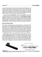
many as 4,200. Figure 7.1 shows some of these items and identifies the signals asso
-
ciated with a twisted pair. They are:
•
Differential mode signals: Signals applied between the wires of a twisted pair.
Also known as metallic signals. Messages are always transmitted as differen
-
tial signals.
•
Common mode signals: Signals measured between the two wires and ground.
Also known as longitudinal signals. Common mode signals are created by
outside interference (noise).
121
TLFeBOOK
Two-way operation over a single twisted pair is achieved by the use of trans-
formers, echo canceling devices, and adaptive filters. Called hybrid mode operation,
the principle is shown in the lower half of Figure 7.1. When a signal is sent from ter-
minal Send1, the combination of the adaptive filter and echo-canceling device pre-
vents it from appearing at terminal Receive1. Simultaneously, if a signal is sent from
terminal Send2, terminal Receive1 receives it without interference from Send1.
Hybrid operation eliminates the need to run a second pair to each subscriber to
obtain a duplex circuit.
7.1.1 Cable Pair Impairments
Cable pairs are subject to impairments produced by installation procedures. For
instance, in areas where cables have been installed in anticipation of demand, less
than the full length of the cable pair may be used to serve an existing subscriber. The
remainder is left attached but not terminated. It is called a bridged tap, which is a
cable pair continued beyond the point at which the pair is connected to a subscriber
or an unterminated cable pair attached to an active cable pair.
Because they load the active pair, bridged taps increase the attenuation of the
signal and create impedance discontinuities. The higher attenuation lowers the
signal-to-noise ratio at the receiver and the impedance discontinuities cause signal
reflections that can adversely affect the data stream. Figure 7.2 shows some bridged
tap arrangements. They are anathema for most data circuits, although digital sub
-
scriber line (DSL) equipment operates with limited tap lengths.
Another installation practice that is detrimental to digital signals is the use of
loading coils. As the length of the cable pair increases, the attenuation increases.
Because of the capacitance of the pair, the higher voice frequencies suffer more
122 Transmission Facilities
Twisted pairs
Ground
Common mode
Differential mode
Source
Load
Tip
Ring
Binder
Bundle
Differential mode
common mode
Hybrid2
Send2
Receive2
Echo
canceller
Σ
+
−
−
Echo
canceller
Σ
+
Send1
Receive1
Hybrid1
DTE1
DTE2
Cable Pair
Principle of hybrid mode operation (two-way on single pair)
Adaptive
filter
Adaptive
filter
Figure 7.1 Differential, common, and hybrid modes in twisted pair operation.
TLFeBOOK
attenuation than the lower voice frequencies. Eventually, the voice signal becomes
unintelligible due to the loss of these frequencies. On long connections (over 18,000
feet), it was standard practice to add loading coils to improve voice signal perform-
ance. Loading may be present on 19-, 22-, and 24-gauge loops longer than 18,000
feet, or 26 gauge loops longer than 15,000 feet. D66 loading consists of 66-mH coils
spaced 4,500 feet apart. H88 loading consists of 88-mH coils spaced 6,000 feet
apart. The first load coil from the CO is located a half-section out. However, the
additional inductance has an adverse effect on digital signals, and the coils must be
removed before the connection can be used for data. Modern practice relies on
equalizers to compensate for unequal frequency attenuation.
One further installation practice should be noted. To ensure reliable ringing
(and reliable disconnects) of telephones powered from the cable pair, a current of
greater than 25 milliamps is required. With a 48-volt battery in the CO, a 26-AWG
(American Wire Gauge) copper wire loop can connect points up to a maximum
9,000 feet apart (carrier serving area). To serve loops longer than this, larger size
wires are added. As the distance from the CO increases, the wire size is increased
from 26 to 24 to 22 and (rarely) 19 AWG. If space permits in the CO cable vault, 24
AWG pairs alone can be used to 12,000 feet. At the junction points, the changes
in wire diameter produce impedance changes that create reflections and may have
an adverse effect on digital signals. In selecting a cable pair connection for data,
the one with the least number of wire size changes is likely to provide the best
performance.
4.1.2 Circuit Noise
Signals are subject to corruption by many events. Collectively, the interference is
known as noise, which is the sum of all unwanted signals added to the message sig
-
nal in the generation, transmission, and reception processes.
Figure 7.3 illustrates the transmission environment in which the major noise
contributor is longitudinal current. These currents are produced in tip and ring by
voltages to ground. If the loop is balanced to the ground, they are of equal magni
-
7.1 Twisted Pairs 123
< 9 kft on 26 AWG pair
< 12 kft on 24 AWG pair
> 1 kft
No more than 2 BTs
First more than 1 kft from CO
Longest BT < 2kft
Total BT len
g
th < 2.5 kft
BT
BT< 2 kft
Limitations based on carrier serving area (CSA) specifications
Subscriber
terminal
Central office
or remote terminal
Active loop
Figure 7.2 Bridged taps.
TLFeBOOK
tude and flow in the same direction so that the voltage between tip and ring is zero.
However, if the loop is unbalanced to ground, signals due to the longitudinal cur
-
rents will be measured between tip and ring. On an idle circuit, this is known as cir-
cuit noise, which is also known as metallic, background,ordifferential noise. Using
a band-limited weighting filter, it is the power measured between tip and ring when
no message signal is present.
A common filter weights the noise frequencies in proportion to their perceived
annoyance. The output of the filter is expressed in dBrnC, decibels referenced to
noise with C-weighting. Circuit noise has two major components:
•
Power influence: Noise caused by inductive interference from the public
power system. Radiation from the public power system comprises fundamen-
tal (60 Hz) and harmonic (n×60 Hz) frequencies. Telephone equipment is sus
-
ceptible to harmonics, especially those above 300 Hz. (Interference from
three-phase power systems is somewhat less than from single-phase systems
because even harmonics cancel out leaving only the odd harmonics to generate
interference.)
•
Impulse noise: Short, intense bursts of noise. For telephone purposes, it is
defined as a voltage increase of greater than 12 dB above the root-mean-
squared (rms) background noise that lasts less than 10 ms. Impulses are pro
-
duced by lightning strikes, certain types of combustion engines, and sudden
changes in load due to catastrophic events. A pair with circuit noise less than
20 dBrnC is rated good. On long rural routes, less than 26 dBrnC is accept
-
able. Above 40 dBrnC, the circuit is unacceptable.
7.1.3 Crosstalk
Other interfering signals are generated by crosstalk between circuits. Crosstalk
occurs when signals between an unbalanced tip and ring (differential mode signals)
generate electromagnetic fields that induces interfering signals in nearby pairs. Cros
-
stalk is a factor in limiting the rate at which data can be sent, and the distance over
124 Transmission Facilities
Ground
Tip
Ring
Impulse
Impulse noise
Power influence
Longitudinal noise
Power influence
Message
Message
+ circuit
noise
Figure 7.3 Noise components.
TLFeBOOK
which it may be sent (data reach). Figure 7.4 shows the major components of cros
-
stalk in a paired cable. It is divided into near-end crosstalk and far-end crosstalk:
•
Near-end crosstalk (NEXT): A condition in which a signal transmitted over a
twisted pair in a paired cable creates a disturbance in other pairs at the same
end of the cable. Near-end crosstalk is produced by interference from the
transmitting wire of one pair to the receiving wire of another pair measured at
the receiving point at the same end of the cable. The magnitude is independent
of the length of the cable. NEXT can be a major impairment in systems that
share the same frequency band for downstream and upstream transmissions.
(The downstream direction is from the CO to the subscriber. The upstream
direction is from the subscriber to the CO.) When different frequency bands
are used, NEXT between downstream and upstream signals is avoided.
NEXT can be divided into:
•
SNEXT: Crosstalk from the same type of signal running in the same binder
(self-crosstalk);
•
FNEXT: Crosstalk from a different type of signal running in the same
binder (foreign crosstalk).
Near-end crosstalk is the sum of self-crosstalk and foreign crosstalk. As
shown in Figure 7.4, crosstalk also affects equipment at the far end of the
cable.
•
Far-end crosstalk (FEXT): A condition in which a signal transmitted over a
twisted pair in a paired cable creates a disturbance in other twisted pairs at the
far end of the cable. Far-end crosstalk is produced by interference from the
transmitting wire of one pair to the receiving wire of another pair measured at
the receiving point at the far end of the cable. Its magnitude depends on the
length of the cable. Like NEXT, FEXT is composed of SFEXT and FFEXT
and can be avoided if different frequency bands are used for downstream and
upstream signal streams.
Because larger numbers of wire pairs are bundled together in feeder cables of
finer wire, crosstalk is more severe at the CO end of a connection. At the subscriber
7.1 Twisted Pairs 125
NEXT near-end crosstalk FEXT far-end crosstalk
Disturbing Pair
Disturbed pair
Cable
TX transmitter
RX receiver
TX
RX
TX
RX
TX
RX
TX
RX
Interfering Signal
Figure 7.4 Crosstalk components.
TLFeBOOK
end, where there are fewer and coarser wires, the level of crosstalk is less severe. This
means that the upstream signal-to-noise ratio at the central office will be less than
the downstream signal-to-noise ratio at the pedestal. Accordingly, higher rate sig
-
nals can be transmitted downstream to the customer than can be transmitted
upstream to the central office.
7.2 Transport Based on Twisted Pairs
Twisted pairs are used to transport digital signals operating from 2.4 kbit/s to 55
Mbps and higher. Common twisted pair digital loops are:
•
Subrate digital: 2.4–56 kbit/s; symmetrical channels (i.e., upstream and down
-
stream channels operate at same speed); employs one pair.
•
T-1 carrier: 1.544 Mbps; symmetrical channels; employs two pairs, one for
each direction; with repeaters every 6,000 feet, operates up to 50 miles; uses
AMI line code (see Appendix A).
•
ISDN subscriber lines:
•
Basic rate (BRI): 160 kbit/s; symmetrical channels; employs one pair; oper-
ates to 18,000 feet; uses 2B1Q line code (see Appendix A).
•
Primary rate (PRI): 1.544 Mbps; symmetrical channels; operates over any
existing DS-1 rate transmission systems (e.g., repeatered T-1 or HDSL).
•
Digital subscriber lines:
•
High bit-rate DSL (HDSL): 1.544 Mbps; symmetrical channels; employs
two pairs (dual-duplex); without repeater operates to 12,000 feet, with one
repeater (doubler) operates to 24,000 feet; with two repeaters operates to
36,000 feet; uses 2B1Q line code.
•
Single-pair high-data-rate DSL (G.shdsl): Up to 2.32 Mbps; symmetrical
channels; employs one pair; operates up to 24,000 feet without repeater.
•
Asymmetric DSL (ADSL): Up to 8 Mbps downstream and up to 640 kbit/s
upstream, employs one pair; operates to 12,000 feet without repeater.
•
Very high-speed DSL (VDSL): 13 Mbps and 26 Mbps symmetrical, or 52
Mbps downstream and 6.4 Mbps upstream; employs one pair; operates
over short distances between fiber access nodes and clusters of buildings.
The bit rates quoted are actual line rates. The user’s data rate is something less
than these rates. Some units require two twisted pairs; others use only one. The dif
-
ferences between the performance of DSLs reflects the year in which each was stan
-
dardized and the capability of digital electronics at the time.
7.2.1 Transmission System 1 (T-1)
The first digital transmission equipment widely deployed in the Bell System was T-1
(transmission system 1). In its original application, it carries 24 multiplexed voice
channels at a speed of 1.544 Mbps. Multiplexing is the action of interleaving several
signal streams so that they can be carried on a single bearer. A multiplexer combines
126 Transmission Facilities
TLFeBOOK
several digital signals into a higher speed digital stream. Each voice signal is sampled
8,000 times per second, and the sample values are companded and coded in 8-bit
words. Companding (derived from the words compressing and expanding) is the
action of reducing the dynamic range of a signal so an approximately equal number
of samples are present at each quantizing level for digitizing. The samples are com
-
pressed so that higher-value amplitudes are reduced with respect to lower-level
amplitudes. This makes more quantizing codes available to lower level signals and
improves the signal-to-noise ratio. To convert compressed samples back to some
-
thing close to their original levels, the amplitudes of the samples are expanded. The
digital values are transmitted over two cable pairs (one for each direction) and alter
-
nate mark inversion (AMI) signaling is employed (see Appendix A). At least 90% of
the signal energy is distributed between 0 Hz and 1.5 MHz with a peak at around
700 kHz. The signals are amplified, reshaped, and retimed by repeaters spaced
6,000 feet apart (except the first and the last which must be within 3,000 feet of the
terminals). Normally, because of jitter in the timing circuits, a T-1 line is limited to
no more than 50 repeaters.
T-1 established certain parameters that have permeated the modern public
switched telephone network (PSTN). For instance, in the digitizing process, the ana
-
log voice signal is sampled at 8,000 samples per second. This limits the bandwidth
of a reconstructed analog voice signal to 4 kHz (see Appendix A). With an 8-bit
quantizing code, the basic digital voice rate becomes 64 kbit/s. Quantizing is the
process that segregates sample values into ranges and assigns an 8-bit code to each
range. Whenever a sample value falls within a range, the output is the code assigned
to that range. Known as DS-0 (digital signal level 0), 64 kbit/s is the basic building
block for all higher-speed services, whether voice or data. When used for data, the
functions of sampling, companding, quantizing, and coding described earlier are
not employed.
7.2.1.1 Data T-1
Figure 7.5 shows a T-1 configured for data-only operation. It differs from T-1 voice
in that the twenty-fourth byte of each frame is used as a signaling channel. In T-1
voice, all 24 bytes are used for voice channels with per channel signaling provided
by bit robbing in every sixth byte of each channel. In data operation T-1 consists of
multiplexers connected to terminal repeaters that are then connected to one another
over two twisted pairs punctuated by line repeaters. To emphasize the flexibility of
T-1, I have included a second multiplexer that multiplexes subrate (i.e., 2.4, 4.8,
9.6, and 19.2 kbit/s) duplex data lines to 64 kbit/s. The multiplexer sends a bipolar
signal to the terminal repeater and receives a similar signal from it. The terminal
repeaters convert the bipolar stream to AMI format, time the outgoing signals, and
regenerate the incoming signals.
Full-rate (64 kbit/s) data channels are interleaved to create a 1.544-Mbps data
stream. Figure 7.6 shows the formation of a T-1 data frame. For simplicity, only one
direction of transmission is shown. For duplex operation, a second frame must be
created from bytes sent in the reverse direction. The frame consists of 23 bytes of
payload, 1 byte of signaling data, and a framing bit (known as the 193rd bit). Each
frame is transmitted at a speed of 1.544 Mbps in 125 µs (the voice sampling time).
For the repeaters to function correctly, 12.5% (1 in 8) of the bits must be 1s, and
7.2 Transport Based on Twisted Pairs 127
TLFeBOOK
there can be no more than 15 consecutive 0s. To ensure meeting these figures the last
bit of every data byte is set to 1. This action reduces the per channel data throughput
to 56 kbit/s. With 23 data channels, the data throughput becomes 1.288 Mbps per
T-1 line. To distinguish signaling bytes from data bytes, the eighth bit in a signaling
byte is set to 0.
7.2.1.2 64-kbit/s Clear Channel
To make entire 64-kbit/s channels available to users (64-kbit/s clear channel capabil
-
ity), special coding that is transparent to the user is introduced into all-0s bytes.
Called bipolar with 8 zeros substitution (B8ZS), bipolar violations are inserted in bit
positions 4 and 7 of all-0s bytes. In an AMI signal, the 1s polarity alternates regu
-
larly. A bipolar violation is a 1 with the same polarity as the previous 1. Because of
the violations (bits 4 and 7), the receiver can detect the pattern (bits 4, 5, 7, and 8)
and remove it before processing. Each violation is followed by a normal 1 (in posi
-
tions 5 and 8). Thus, 00000000 becomes 1V01V000 (Bit 8 ← Bit 1, canonical
format), a pattern that more than meets the 1s requirement. The receiver reverses
this substitution to produce the original data stream.
Another technique requires four frames (96 bytes) to be stored in a buffer.
Called zero-byte time slot interchange (ZBTSI), all-0s bytes are removed, and
the remaining nonzero bytes consolidated at the rear of the buffer. This leaves as
many spaces at the front of the buffer, as the number of all-0s bytes. Into these
spaces, seven bit numbers are entered that correspond to the positions of the all-0s
bytes in the stream of 96 bytes. The eighth bit in the byte is used to indicate
whether more all-0s bytes follow. At the receiver, the stream is reassembled with
all-0s bytes in their correct position. This processing delays the stream by approxi
-
mately 1.5 ms.
128 Transmission Facilities
Subrate
multiplexer
Subrate
data lines
Various rate
data lines
Data payload
1.288 Mbits/s≤
Terminal
Repeater
Line
repeater
Line
repeater
Subrate
multiplexer
Full rate
multiplexer
Repeater
3000 feet≤
6000 feet
3000 feet≤
ESF controller
DSU/
CSU
Terminal
DSU/
CSU
Repeater
Full rate
multiplexer
Figure 7.5 T-1 data-only configuration.
TLFeBOOK
7.2.1.3 Framing Bits and Extended Superframe
The framing bit acts as a marker to synchronize the electronics and ensure the
boundaries of each byte are detected correctly. Framing bits in consecutive frames
are used to provide control patterns and error information. Two arrangements are a
12-frame superframe (SF) and a 24-frame extended superframe (ESF).
Figure 7.7 shows the 24-frame ESF. To make such a diagram, twenty-four 193-
bit frames are stacked on top of one another. By doing this, individual channels
appear as columns and the 193rd bits appear as a column at the left-hand side of the
frame. They perform three functions. The six F bits in frames 4, 8, 12, 16, 20, and
24 form the pattern 101010. It is used to synchronize electronics and ensure that the
receiver remains locked to the frame structure. The 12 D bits provide a 4,000-bps
data link facility that forwards specific application information or historical data
for maintenance use. The six C bits in frames 2, 6, 10, 14, 18, and 22 are the frame
check sequence of a cyclic redundancy check that monitors the error performance of
the 4,632-bit superframe. The bit stream is divided by a 7-bit polynomial (1000011)
to give a 6-bit FCS. Error checking is used to measure the performance of T-1 facili
-
ties (see Section 4.3).
7.2 Transport Based on Twisted Pairs 129
Byte 1
Byte 2
Byte 1 Byte 2
Byte 3
Byte 3 Byte 1Byte 24
Byte 23
Byte 24
Frame
n 1−
Frame
1 byte = 5.18 secsµ
1 Frame = 125 secsµ
Framing Bit for Frame n+1
193 rd bit
Framing Bit for Frame n
193 rd bit
T-1 Frame
Payload
1 bit = 0.648 secsµ
Byte 23
Byte 24
Byte 24
11
1
11
0
1
In data bytes, the 8th bit is set to 1 to meet the T-1 12.5%
1s requirement
Data Payload 23 bytes (184 bits) minus 23 bits = 161 bits
Data Throughput = 1.288 Mbits/s
Full 64 kbits/s clear channel can be achieved
using B8ZS or ZBTSI
1
1
1
1
0
In signaling bytes, the 8th bit is set to 0 to indicate it is
a carrier-controlled byte
T-1 speed 1.544 Mbits /s
Data stream
n + 1
Signaling
Figure 7.6 T-1 data frame format.
TLFeBOOK
7.2.1.4 T-Carrier Family
T-1 was the first in a hierarchy of multiplexed transmission systems developed to
carry digital voice circuits in ever increasing numbers. The entire family consists of
six units:
•
T-1: Multiplexes 24 DS-0 (64 kbit/s) signals into one DS-1 (1.544 Mbps) sig
-
nal (DS-1 = 24 DS-0s).
•
T-1C: Multiplexes two DS-1 signals into one DS-1C (3.152 Mbps) signal
(DS-1C = 48 DS-0s).
•
T-2: Multiplexes four DS-1 signals into one DS-2 (6.312 Mbps) signal (DS-2 =
96 DS-0s).
•
T-3: Multiplexes seven DS-2 signals into one DS-3 (44.736 Mbps) signal
(DS-3 = 672 DS-0s). Known as T3 SYNTRAN (synchronous transmission), a
special version developed for enterprise networks multiplexes 28 DS-1 signals
directly to DS-3.
•
T-4NA: Multiplexes three DS-3 signals into one DS-4NA (139.264 Mbps) sig
-
nal (DS-4NA = 2076 DS-0s).
130 Transmission Facilities
Frame 1
2
3
4
5
6
7
8
9
10
11
12
13
14
15
16
17
18
19
20
21
22
23
Frame 24
S
i
g
n
a
l
i
n
g
B
y
t
e
s
Extended superframe (ESF)
D
C
D
F
D
C
D
F
D
C
D
F
D
C
D
F
D
C
D
F
D
C
D
F
Framing bits
Subchannels
F = Framing
D = Data link
C = CRC/FCS
23 data bytes
23 data bytes
23 data bytes
23 data bytes
23 data bytes
23 data bytes
23 data bytes
23 data bytes
23 data bytes
23 data bytes
23 data bytes
23 data bytes
23 data bytes
23 data bytes
23 data bytes
23 data bytes
23 data bytes
23 data bytes
23 data bytes
23 data bytes
23 data bytes
23 data bytes
23 data bytes
23 data bytes
Figure 7.7 T-1 Extended superframe format.
TLFeBOOK
•
T-4: Multiplexes six DS-3 signals into one DS-4 (274.176 Mbps) signal (DS-4
= 4032 DS-0s).
Only T-1 and T-1C operate on twisted pairs. Byte-level multiplexing is used in
T-1 and T-3 SYNTRAN. In turn, a byte from each input line is assembled in a frame
with framing and control bits, and placed on the output line. Bit-level multiplexing
is used in T-1C, T-2, T-3, T-4NA, and T-4. In turn, a bit from each input line is
assembled in a subframe with framing and control bits, combined with other sub
-
frames, and placed on the output line. Only T-1 and T-3 SYNTRAN have found
major employment in a data environment. In many applications, digital subscriber
lines are replacing T-1, and T-3 is being replaced by SONET.
7.2.2 ISDN
In the 1970s, with the development of digital computers, growing demands for data
communication, and the perfection of digital voice, it became apparent to many
PSTN operators that an all-digital network could carry both voice and data traffic.
Called integrated services digital network (ISDN), it gave impetus to the develop
-
ment and deployment of digital switches. Later, with the invention of digital
television, the concept was expanded to include video. The idea of a broad-
band, multimedia, digital network was born. Called broadband ISDN (B-ISDN), it
gave impetus to the development of ATM switches, synchronous optical network
(SONET), and synchronous digital hierarchy (SDH) transmission systems (see Sec-
tions 7.4.1 and 7.4.2).
Many problems had to be solved, including how to provide digital chan-
nels to individual subscribers. Presently, ISDN supports two service speeds—
160 kbit/s (128- or 144-kbit/s payload) and 1.544 Mbps (1.472-Mbps payload).
They provide a combination of bearer (B) channels and signaling (D, for delta or
data) channels.
Basic Rate ISDN provides 2 × 64 kbit/s B channels, 1×16 kbit/s D channel, and
16 kbit/s overhead, for a total of 160 kbit/s. Designed to serve customers with non
-
loaded loops, its reach is 18,000 feet. To reduce signal attenuation over the longer
loops, AMI coding was replaced by 2B1Q coding (see Appendix A). Achieving 2 bits
per baud efficiency, at least 90% of the signal energy is distributed between 0 Hz
and 772 kHz. Two-way operation over a single cable pair is achieved through the
use of echo cancelers. Neither loading coils nor bridged taps can be present.
Primary-rate ISDN provides 23 × 64 kbit/s B channels and 1 × 64 kbit/s D chan
-
nel to a customer. With a separate signaling channel, the customer has access to the
full 64 kbit/s (clear-64) in the 23 B channels. B channels can be aggregated into H0
channels (384 kbit/s) and H11 channels (1.536 Mbps). For H11 channels, signaling
is provided by a D channel from another primary rate interface. As in T-1, a frame
consists of 24 bytes to which a framing bit (193rd bit) is added. In addition, a multi
-
frame structure is created that consists of twenty-four 193-bit frames. Framing bits
in frames 4, 8, 12, 16, 20, and 24 are used to maintain frame synchronization. How
-
ever, the code is different from T-1—it is 001011. Primary rate ISDN is provided
over two cable pairs using any DS-1 transmission system such as repeatered T-1 or
HDSL (see Section 8.1.2).
7.2 Transport Based on Twisted Pairs 131
TLFeBOOK
7.3 Optical Fibers
Optical carriers used for communication are located in the infrared portion of the
spectrum between 250 and 450 THz (Terahertz, 1 THz = 3 × 10
14
Hz). They have
wavelengths from approximately 0.85 µ to 1.6 µ (1 µ = 1 micron = 1 meter × 10
−6
). It
is usual to specify them in terms of wavelength rather than frequency. Optical fibers
are superior to twisted pairs in several ways:
•
Because optical energy is not affected by electromagnetic radiation, it is
immune from noise generated by common electromagnetic sources.
•
Because the optical energy is focused in the center of the fiber and the coating
(buffer) is impervious to infrared wavelengths, crosstalk is of no concern in
optical fiber cables. All of the optical energy is guided along the fiber.
•
Because the frequencies of optical carriers are very high compared to conceiv
-
able message bandwidths, they can be used to transport very wideband mes
-
sage signals.
•
Because optical fiber cables can be much smaller than paired cables, in areas in
which underground ducts are used, the substitution of fiber cables for paired
cables frees significant space for future expansion.
Compared to copper wires, optical fibers have disadvantages:
•
Optical energy propagates in only one direction along the fiber. Two fibers are
needed to make a duplex circuit.
•
Optical fibers are insulators; they do not conduct electricity. Therefore, they
cannot carry electrical power for operating repeaters and other electrical
devices. Powering equipment through the line is only possible if copper wires
are added to the cable.
•
Microbends and other mechanical insults increase fiber loss. In comparison,
they have no effect on copper wires.
7.3.1 Single-Mode Fiber
The predominant design in telecommunications applications is single-mode fiber. It
is a strand of exceptionally pure glass with a diameter about that of a human hair
(125 micron = 0.005 inch). The refractive index varies from the center to the outside
to focus optical energy in the center of the strand and guide it along the length.
Shown in Figure 7.8, in such a fiber, the central glass core is less than 10 microns in
diameter and of higher refractive index than the glass cladding. With a refractive
index of 1.475, the velocity of energy in the core is approximately 200,000 km/sec
(i.e., approximately two-thirds the velocity of light in free-space). A significant (and
essential) fraction of the optical energy travels in the cladding glass. Because its
velocity is slightly higher (around 211 km/sec) than the energy in the core, condi
-
tions are right to support single-mode propagation.
132 Transmission Facilities
TLFeBOOK
7.3.2 Optical Properties
Single-mode fibers are used with solid-state laser transmitters and photodiode
detectors that operate at wavelengths around 1,550 nanometers (1 nanometer =
1 meter × 10
−9
; 1,550 nm = 1.55 micron). The lasers are switched on and off to pro
-
duce pulses of infrared energy. At 1,550 nm, the fiber has an attenuation of around
0.2 dB/km (i.e., a loss of approximately 5% per kilometer, or 8% per mile). Spans of
up to 60 miles can be achieved without using a repeater, and repeaterless spans of up
to 130 miles have been achieved in undersea cables.
7.3.3 Wavelength Division Multiplexing
Several optical carriers can be transmitted simultaneously in the same single-mode
fiber. Called wavelength division multiplexing (WDM), current practice employs up
to 64 carriers, with the expectation that this can be upgraded to 256 carriers in the
near future, and perhaps as many as 400 carriers eventually. The term dense wave
-
length division multiplexing (DWDM) is used to describe systems that employ these
higher numbers of wavelengths. Crosstalk is a major concern in WDM. Interference
is produced by imperfections in network components and by fiber nonlinearities
that scatter the optical energy of the carriers.
7.3.4 Optical Amplifiers
Very long-distance WDM transmission is made possible by optical amplifiers. As
shown in Figure 7.9, in one design a length of erbium-doped fiber is placed in the
7.3 Optical Fibers 133
Figure 7.8 Single-mode optical fiber.
TLFeBOOK
optical path. Arrangements are made to pump this fiber with energy at 980 or
1,480 nm. Optical isolators are used to terminate the fiber. They restrict the pump
-
ing energy to the erbium fiber. In this fiber, the Er
3+
ions are raised to a metastable
state from which they spontaneously decay to the ground state. Because the isolators
do not stop the WDM carriers, the photons of the message streams collide with
(stimulate) the metastable ions. As the stimulated ion returns to the ground state, it
emits a photon with the same wavelength, phase and direction as the photon it col-
lided with (stimulated emission). Because a single photon can stimulate many ions,
the result is amplified streams of coherent photons at the signal wavelengths. Ions
that are not stimulated by a photon spontaneously decay to the ground state. In
doing so, they emit incoherent radiation that contributes to amplifier noise. Called
EDFAs, Erbium-doped fiber amplifiers produce gains of up to 40 dB between 1,530
and 1,610 nm (C-band, 1,530–1,565 nm; and L-band, 1,570–1,610 nm).
7.3.5 Short-Distance Facilities
For short distances, in a building or on a campus, the fiber can be made of plastic
with a core of elevated refractive index or glass with a core over which the refractive
index varies in a graded manner. Called step index and graded index fibers, they are
shown in Figure 7.10. The energy propagates in multimode fashion along the core.
Because many ray paths are possible, each with a slightly different length, the signal
is dispersion-limited, and the distance-bandwidth product is significantly less than
that of single-mode fiber. Nevertheless, for short distances, multimode fiber installa
-
tions are reliable and relatively cheap.
7.4 Transport Based on Optical Fibers
Unlike wire, on which the signal propagates in both directions, fiber is a one-way
bearer, and two are needed to complete a circuit. Pairs of optical fibers are used in
point-to-point applications, and other topologies in which the need for access at
intermediate points can be limited. To provide transport between major traffic junc
-
tions, telephone companies use a flexible, multipurpose, ring-like architecture. They
employ two or four fiber rings to ensure fiber paths are available to recover from
134 Transmission Facilities
Pump
Amplified
energy 1530
to 1610 nm
Optical Isolator
Erbium-Doped fiber
Optical isolator
Attenuated
energy 1530
to 1610 nm
Stimulated emission
in this region
leads to amplification
940 or 1480 nm
Figure 7.9 Principle of Erbium-doped fiber amplifier.
TLFeBOOK
service interruptions. While transmission is by optical means, all signal processing is
accomplished electronically.
7.4.1 Synchronous Optical Network
Synchronous optical network (SONET) is an all-digital, optical fiber transport
structure that operates from 51.84 Mbps to 40 Gbps (Gbps = gigabits per second =
1,000 Mbps = 10
9
bps), and beyond. SONETs serve as very high-speed backbones in
the Internet, as high-speed distribution networks in local exchange and interoffice
facilities, and provide optical transport channels for private connections. Figure
7.11 shows the principle of SONET. The basic configuration is a double fiber ring in
which the fibers operate in opposite directions. Should a fault occur in a link, traffic
is routed back on itself to complete the journey to its destination. A SONET may
contain equipment that performs the following functions:
•
Add/drop multiplexer (ADM): Aggregates or splits SONET traffic at various
speeds so as to provide access to SONET without demultiplexing the SONET
signal stream. Generally, it has two equal speed network connections.
•
Terminal multiplexer (TM): An end-point or terminating device that connects
originating or terminating electrical traffic to SONET. Has only one network
connection.
•
Digital cross connect (DCS): Redistributes (and adds or drops) individual
SONET channels among several STS-N links. Consolidates and segregates
STS-1s, and can be used to separate high-speed traffic from low-speed traffic
(to feed one to an ATM switch and the other to a TDM switch, for instance).
7.4 Transport Based on Optical Fibers 135
Figure 7.10 Short-distance fibers.
TLFeBOOK
•
Digital line carrier (DLC): Used to link serving offices with carrier serving area
(CSA) interface points. Typically, SONET DLCs concentrate DS-0 signals into
OC-3 signals.
•
Matched node (MN): Pairs of MNs are used to interconnect SONET rings and
provide alternate paths for recovery in case of link failure. SONET traffic is
duplicated and sent over two paths between the rings. One set of MNs pro
-
vides the active path; the other set is on standby in case of failure of the active
connection.
•
Drop-and-repeat node (D+R): SONET devices configured to split SONET
traffic and copy (repeat) individual channels on two or more output links.
Applications include the distribution of residential video and alternate rout
-
ing. (This is not shown in Figure 7.11.)
7.4.1.1 SONET Signals
While SONET is an optical transmission system, the signals at the fiber ends are con
-
verted to electrical form for processing. SONET standards define a set of opti
-
cal/electronic interfaces for network transport. The electrical signal hierarchy has N
members.
136 Transmission Facilities
ADM
DCS
ADM
DLC
CSAI
TM
SONET
ring
Switch
ATM/TDM
Distribution cables
DCS
MNDCS
Local
Regional
Long distance
DCSMNDCS
TM Terminal multiplexer
ADM Add/drop multiplexer
DCS Digital cross connect
MN Matched node
DLC Digital line carrier
CSAI Carrier serving area
interface
Figure 7.11 SONET rings.
TLFeBOOK
•
Synchronous transport signal level 1 (STS–1): With a basic speed of 51.84
Mbps, STS-1 signals are designed to carry T–3 signals or a combination of
T-1, T-1C, and T-2 signals that is equivalent to DS–3.
•
Synchronous transport signal level N (STS-N): With speeds that are multiples
of STS–1 (i.e., n × 51.84 Mbps), STS-N signals are created by byte multiplex
-
ing N STS-1 signals. For various reasons, the values N = 3 (155.52 Mbps), 12
(622.08 Mbps), 24 (1244.16 Mbps), 48 (2488.32 Mbps), 96 (4,976.64
Mbps), 192 (9,953.28 Mbps), and 768 (39,813.12 Mbps) are preferred.
Corresponding to the STS signal hierarchy, the optical signals transmitted over
the fiber facility are:
•
Optical carrier level 1 (OC-1): The optical equivalent of STS-1;
•
Optical carrier level N (OC-N): The optical equivalent of STS-N.
Similar to their electronic counterparts, optical carriers are designated OC-1,
OC-3, , OC-768.
7.4.1.2 SONET Frames
To achieve compatibility with PSTN operations, SONET multiplexers create STS-1
frames of 125-µs duration. Figure 7.12 shows an STS-1 frame. It consists of 810
bytes, of which 774 are payload. To the payload are added 9 bytes of path overhead
to form the synchronous payload envelope (SPE). The path overhead contains data
that monitors and manages the electrical and optical connections between originat-
ing and terminating multiplexers. To the SPE are added 27 bytes of transport
overhead to form a frame. The transport overhead contains data that monitors
and manages the optical line between the originating and terminating SONET
multiplexers.
Payloads that originate from the T-carrier family consist of a fixed number of
bytes every 125 µs. Called virtual tributaries, they occupy 9 rows × n columns in the
SPE. Thus, the virtual tributary for DS-1 consists of 27 bytes (9 rows × 3 columns).
Twenty-four of them are DS-0 bytes from the T1 frame, 2 bytes are overhead related
to the virtual tributary, and 1 byte is framing information. A DS-3 frame consists of
672 bytes (28 × 24). When joined with signaling bytes and stuffing bits that com
-
pensate for speed variations and fill the frame, it occupies a complete STS-1 frame.
STS-N frames are constructed by byte multiplexing lower speed frames. Of
125-µs duration, an STS-N frame is equal to N × STS-1 frames. When a signal fills
more than one STS-N frame, the several frames are defined as a concatenated struc
-
ture and designated STS-Nc. They move through the network as a single entity.
7.4.2 Synchronous Digital Hierarchy
For BISDN applications, ITU standardized a hierarchy of transport systems called
synchronous digital hierarchy (SDH). The levels and frames [known as synchronous
transport modules (STMs)] are exactly three times those of SONET. Thus, synchro
-
nous transport module level 1 (STM-1) is a frame of 2,430 bytes at 155.52 Mbps
(STM-1 = 3 STS-1 = STS-3); and synchronous transport module level N (STM-N) is
7.4 Transport Based on Optical Fibers 137
TLFeBOOK
a frame of N × 2430 bytes at N × 155.52 Mbps. STM-N frames are created by byte
multiplexing N STM-1 frames. STM-N = N STM-1 = 3N STS-1.
In a formal sequence, STM frames are assembled from 125-µ segments of tribu
-
tary signals. Figure 7.13 shows the combinations of tributaries that can form an
STM-1 frame. By adding path overhead, containers (C-11, C-12, C-2, C-3, or C-4)
with a 125-µ segment of a tributary signal are converted to virtual containers
(VC-11, VC-12, VC-2, or VC-3). By adding pointers to indicate the start of the vir
-
tual container, VCs are converted to tributary units (TU-11, TU-12, TU-2, or TU-3).
TUs are grouped together to form a tributary unit group (TUG-2 or TUG-3), and are
combined with path information for the TUG to form another virtual container
(VC-3 or VC-4). By adding pointers to indicate the start of these virtual containers,
the VCs are converted to administrative units (AU-3 or AU-4). Finally, AU-4 or 3
AU-3s are used to create an STM-1 frame. With microwave systems and optical
fibers, the STM format is employed around the world. A notable application is the
undersea fiber cables that encircle the globe. Within the United States, in optical
fibers, the STS format is preferred.
138 Transmission Facilities
Figure 7.12 SONET frame.
TLFeBOOK
7.5 Radio
Called wireless by Heinrich Hertz and its early developers, radio is a means of com
-
munication that employs electromagnetic waves in free space. It is this wireless
property that is so important to us today. It has permitted millions of mobile users
to free themselves from fixed voice networks and communicate from almost any
-
where in an approximately seamless environment. Even at high speed, driving from
one cell into another is accomplished without the user being aware of the change.
Mobile telephones have been adopted the world over as an important adjunct to
enterprise operations and as a means of keeping in touch. The next step is to provide
wireless data communications as an extension of fixed data networks. However, it
is not possible to provide the same transparency for data terminals. Dropping the
radio connection to one access point and establishing a radio connection with
another requires time during which the data stream is not transmitted. In addition,
the vagaries of the electromagnetic medium make radio connections significantly
less reliable than those provided by wires and fibers. Accordingly, a number of spe
-
cial features are included in the communication procedures that govern wireless
data connections. To emphasize the difference, I use the term movable with data ter
-
minals in contrast to mobile telephone.
7.5 Radio 139
C-4
C-3
C-2
C-12
C-11
VC-3
VC-2
VC-12
VC-11
TU-3
TU-2
TU-12
TU-11
TUG-3
TUG-2
VC-4
VC-3
AU-4
AU-3
STM-1
x7
x3
x3
x7
x3
x4
155.52
Mbits/s
139.264
Mbits/s
6.312
Mbits/s
1.544
Mbits/s
Containers
Virtual
containers
Tributary
units
Tributary
unit groups
Administrative
units
Synchronous
transport
module
level-1
Tributary
signals
Virtual
containers
2.048
Mbits/s
44.736
34.368
Mbit/s
Figure 7.13 Tributary multiplexing scheme to create STM-1 frame.
TLFeBOOK
7.5.1 Frequencies and Modulation
Unlike wired point-to-point connections whose number could be increased until the
world’s copper supply is exhausted, the extent of the electromagnetic spectrum in
which radio connections can be made is limited, and competition for slots is fierce.
Consequently, international authorities and national governments control the use of
the radio spectrum. In the United States, the FCC permits unlicensed wireless con
-
nections in three ISM (industrial, scientific, and medical) bands. They are:
•
UHF ISM: 902 to 928 MHz;
•
S-band ISM: 2.4 to 2.5 GHz;
•
C-band ISM: 5.725 to 5.875 GHz.
In addition to wireless network connections, microwave ovens, medical imaging
equipment, and other radiating devices use these bands. To accommodate these dis
-
turbing devices, the communication signal must be robust and immune to high-
levels of interference. To accommodate as many users as possible in the limited
bandwidths available, frequency reuse and noninterfering, low-power signals are
employed. The connections use spread spectrum or orthogonal frequency division
modulation techniques (see Appendix A).
7.5.2 IEEE 802.11 Standard
Sponsored by the organization that standardized Ethernet and Token Ring LANs,
IEEE 802.11 makes use of some of their features. (IEEE 802.11 has been called wire-
less Ethernet.) Figure 7.14 shows the relationship of IEEE 802.11 to the rest of the
802 family of specifications. It employs IEEE 802.2, the logical link sublayer of the
data link layer; uses a unique MAC sublayer that includes collision avoidance; and
has four physical sublayers that accommodate different implementations of the
radio link. In addition, a procedure is added at the MAC/PHY interface. Called the
physical layer convergence procedure (PLCP), it adds fields to the frame for use on
the radio link. The IEEE 802.11 standard defines the infrastructure and frame
formats for complete wireless networks (such as wireless LANs). In last-mile appli
-
cations they are used to provide data communications between movable data termi
-
nals and fixed sites. Popular application locations are airports and other places
where people gather and must wait for service.
IEEE 802.11 includes changes in the bit-ordering conventions. Bits are num
-
bered 0 to 7 in each byte with the least significant bit on the left (bit 0), and the most
significant bit on the right (bit 7). Bytes are numbered 0 to n and read from left to
right, as usual. The change makes for easier manipulation of the bit stream. It is
shown at the bottom of Figure 7.14.
7.5.2.1 Infrastructure
Figure 7.15 shows movable stations, fixed access points (APs), and supporting
equipment. The distribution system above the dashed line in Figure 7.15 can be con
-
figured in many ways. What the diagram suggests is one arrangement. The APs are
tied to a bridge that links them together and, through a router, links them to the
Internet. Servers can be positioned locally or remotely. A number of movable sta
-
140 Transmission Facilities
TLFeBOOK
tions are associated with each AP. They form a basic service set (BSS). With the
bridge connecting the three APs, users in different BSSs can communicate among
themselves as well as access network services. When a movable station moves out of
range of its associated AP, it must join another BSS by associating with the AP
whose BSS it joins. A certain amount of downtime is required while arrangements
are made to host the station and inform the routing tables of the change.
7.5 Radio 141
07Bits
Bytes 0 1 2 n
0707 07
IEEE 802.11 bit and byte order
Data stream
802.3
PHY
802.5
PHY
802.3
MAC
802.5
MAC
802.11 MAC sublayer
802.2 logical link control sublayer
Data link layer
Data link layer
Physical layer convergence procedure (PLCP)
802.11
High-rate
Direct-sequence
Spread spectrum
802.11
Frequency-hopping
Spread spectrum
802.11
Direct-sequence
Spread spectrum
802.11
Orthogonal frequency
Division multiplexing
Physical layer
Figure 7.14 IEEE 802.11 in relation to other members of IEEE 802 family.
BBS basic service set
Movable station
BBS 2
BBS 3
BBS 1
Access
point 2
Access
point 3
Access
point 1
AP
AP
AP
Bridge
Router
Local server
Distribution system
Internet
Remote server
Figure 7.15 IEEE 802.11 basic service set and fixed facilities.
TLFeBOOK
7.5.2.2 Frame Format
The format of an IEEE 802.11 frame is shown in Figure 7.16. A description of each
field is given in Appendix B. The frame includes fields from an IEEE 802.3 frame
that contains an IP packet. They are rearranged and augmented to take account of
the radio link. The header includes four addresses. Addresses 1 and 2 are the destina
-
tion and source addresses as they appear in the 802.3 header. Address 3 is required
to identify the AP/BSS hosting the movable terminal. Address 4 is reserved for future
use.
Because the radio link is established and synchronized in the physical connec
-
tion, the preamble and start fields of the 802.3 header are discarded. In their places
are a frame control field and a duration/ID field. The purpose of the frame control
field is to provide the 802.11 version number and identify the type of frame that fol
-
lows. They are divided into management, control, and data frames. The other bits in
this 2-byte field perform specific alerting functions. The duration/ID field gives the
time in microseconds the originator expects to occupy the radio channel to complete
this transmission. If fragmentation is involved, it is the time to complete the entire
transmission. The time is known as the network availability vector (NAV). It is
noted by all stations in the BSS. They may not transmit during this interval.
Between Addresses 3 and 4, the sequence control field provides information that
allows reconstruction of fragmented frames and detection of retransmitted and
duplicate frames. The frame check sequence field checks the entire 802.11 frame.
7.5.2.3 Collision Avoidance
By reducing collisions and retransmissions, the total time required to transmit
frames over the noisy environment of the ISM bands can be minimized. To do this,
IEEE 802.11 specifies a MAC technique that extends the CSMA/CD routine of Eth-
ernet to carrier sense multiple access with collision avoidance (CSMA/CA). A simpli-
fied diagram of a data exchange between two stations with collision avoidance is
shown in Figure 7.17. Frames employ stop-and-wait ARQ. Before transmitting
data, the sender sends a request-to-send (RTS) control frame to the receiver and
142 Transmission Facilities
Address 1
(destination)
Address 2
(source)
2
26 6
Bytes
Address 3
Sequence
control
Address 4
FCS
2
66
4
53
SNAP header
LLC
header
Parts of IEEE 802.3 frame
IP packet
Frame
control
Duration/
ID
Figure 7.16 IEEE 802.11 frame incorporating IEEE 802.3 frame.
TLFeBOOK
waits for the receiver to reply with clear-to-send (CTS). As soon as the other mov
-
able stations hear the beginning of this exchange, they may not transmit. When the
sender receives the CTS signal, it waits a short time then commences sending data.
At the beginning of this action, all other stations in the BSS received a NAV time.
They know they cannot transmit until it expires. When it does, stations with some
-
thing to send wait a specific interframe time then back off a random number of slots.
If no carrier is sensed, the station with the earliest backoff slot begins with an
RTS/CTS routine and sets the NAV value to the estimated time of its transaction.
IEEE 802.11 specifies three interframe times, also shown in Figure 7.17:
•
DCF interframe space (DIFS): The minimum idle time for contention-based
services. If the channel has been idle for DIFS or longer, stations may have
access to it subject only to random backoff (DCF: distributed coordination
function).
•
PCF interframe space (PIFS): An interval used during contention-free opera
-
tion. Station with permission to transmit contention-free may begin after PIFS
has elapsed and preempt contention-based traffic (PCF: point coordination
function).
7.5 Radio 143
DIFS
PIFS
SIFS
Busy
Contention window
Backoff slots
RTS
SIFS
CTS
X
1
12
1
Data 1
ACK1
2
1
Data 2 ACK0
2
Contention window
X
3
DIFS DCF interframe space
DCF distributed coordination function
PIFS PCF interframe space
PCF Point coordination function
SIFS Short interframe space
SIFS
SIFS
SIFS SIFS
DIFS
PIFS
SIFS
Time
Time
Time
Station 1 sending
to Station 2; Station 2 responding
Station 1 sending to Station 2;Station 2 responding
Busy
Busy
Station 3 begins sending
Figure 7.17 Illustrating collision avoidance.
TLFeBOOK
•
Short interframe space (SIFS): An interval used for high-priority transmissions
such as RTS/CTS frames and ACKs. SIFS is less than DIFS. Once a multiframe
transmission has begun, subsequent frames are sent after SIFS interval. This
preempts other frames that must wait for DIFS.
By using SIFS and extending the NAV as required, stations occupy the channel
as long as necessary.
7.5.2.4 Security
Wireless signals are relatively easy to intercept. In the days when mobile radio used
analog FM, many people though it fair game to listen in to other peoples’ conversa
-
tions. With the move to digital signals and spread spectrum modulation, eavesdrop
-
ping is more difficult, but still can be done by determined listeners using more
complex equipment. The question arises: How secure should IEEE 802.11 opera
-
tions be? Like all questions of this kind, the answer is: It depends! It depends on the
value of the information being passed over the link, and whether it must be pro
-
tected for an hour, a day, a year, or forever. The quicker the information ages, the
less concern there will be over keeping it secure, and it can never be completely pro
-
tected. Given enough time and a fast enough computer, even state secrets are made
known to the competition.
In truth, to be effective, several layers of security are needed. Starting with the
weakest, which guards against casual compromise, and ending with the strongest,
which guards against determined, well-prepared adversaries, they should be invoked
according to the priority afforded security. IEEE 802.11 includes a symmetric key
security procedure called Wired Equivalent Privacy (WEP). Its effectiveness depends
on the length of the secret key used in ciphering and deciphering, and the size of the
community with which each secret key is shared. Too large, and the probability of
compromise is certain. Too small, and the problems of generating numbers of keys
and distributing them in a timely (and regular) fashion becomes an administrative
nightmare. Characterized by some as weak, WEP provides security against casual
-
compromise and not very determined adversaries. The 802.11 Committee is investi
-
gating opportunities to strengthen it. The strongest performance will always be given
by encryption at the source using a one-time-only random key before entering the
communication system.
144 Transmission Facilities
TLFeBOOK