BUILDING REMOTE ACCESS NETWORKS phần 3 ppsx
Bạn đang xem bản rút gọn của tài liệu. Xem và tải ngay bản đầy đủ của tài liệu tại đây (428.17 KB, 60 trang )
Using PPP To Provide Remote Network Access • Chapter 3 97
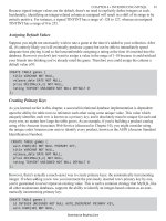
When multiple Cisco access servers are configured using MMP, the
grouping is referred to as a “stack group.” Supported interfaces for MPP
are PRI, BRI, Serial, and Asynchronous.
MMP requires that each associated router be configured with the fol-
lowing parameters:
■
PPP
■
Stack Group Bidding Protocol (SGBP)–A protocol for arbitrating the
location of bundles within a stack group to the “highest bidder”
(normally the stack group member that locates the initial bundle
for the first link in a multilink connection)
■
MP
■
Virtual template for interface cloning
Simple stack groups are composed of member peer routers and do not
need to have a permanent “lead” router. Any stack group member who
answers an incoming call becomes the “owner” of the call, if it is the first
call in a new session with the particular remote-end device.
When a second call comes in from this same remote-end device to the
stack group, the answering router will forward the call to the stack group
where the member routers will “bid” for the call. Since the first router
“owns” the session by answering the first call, it will win the bid and the
answering router will forward the call to it.
www.syngress.com
Workstation
Modem
Modem
PPP Multichassis Multilink
Workstation
PSTN
ISDN
Plain old telephone service (POTS)
PRI
Figure 3.12 MMP configuration using routers.
93_sbcran_Ch03 10/16/00 2:29 PM Page 97
98 Chapter 3 • Using PPP To Provide Remote Network Access
The second router accomplishes this by establishing a tunnel to the
“owner” router and forwarding all packets to the owner. The owner router
is responsible for reassembling and resequencing the packets. The owner
router then forwards these packets on to the local network.
There are two basic steps to configuring MMP on Cisco routers and
access servers:
Step 1 Configure the stack group and make member assignments.
1. Create the stack group on the first router to be configured, where
“name” is the hostname of that router.
[sgbp group group_name]
2. Add additional stack group members.
[sgbp member router2_hostname router2_ip_address]
[sgbp member router3_hostname router3_ip_address]
<add additional sgbp member lines for each additional member router>
Step 2 Configure a virtual template and Virtual Template Interface.
1. Create a virtual template for the stack group.
[multilink virtual-template template_number]
2. Create IP address pool (a local pool is used in this example).
[ip local pool default ip_address]
3. Create a Virtual Template Interface (not required for ISDN inter-
faces or if physical interfaces are using dialers).
[interface virtual-template template_number]
4. Use unnumbered IP addressing.
[ip unnumbered ethernet 0]
5. Configure PPP.
[encapsulation ppp]
6. Enable Multilink PPP.
[ppp multilink]
7. Enable PPP authentication.
[ppp authentication type]
www.syngress.com
93_sbcran_Ch03 10/16/00 2:29 PM Page 98
Using PPP To Provide Remote Network Access • Chapter 3 99
Verifying and Troubleshooting PPP
Sometimes problems arise when configuring PPP for remote access servers.
Cisco provides a very powerful and robust set of commands to aid in iso-
lating problems and solving communication problems. These commands
exist in two different command sets: show commands and debug com-
mands.
Show commands are used to determine the current status of an inter-
face or protocol, whereas debug commands are used to show the processes
an interface or protocol executes in order to establish continuity or com-
munication.
Basic troubleshooting involves ensuring that the hardware is func-
tioning correctly, then checking to see that configurations are correct and
communication processes are proceeding normally over the wire. You
should start at the physical layer and work your way up the OSI model to
determine where the problem(s) are in establishing the connection.
PPP and Cisco Access Servers
Below are some basic steps that you can use to troubleshoot remote con-
nections to a Cisco access server.
1. Does the user’s modem connect? If No, use these commands to
determine the status of the modem: show modem log, debug
modem.
2. Does the LCP negotiation succeed? If No, use these commands to
determine the point of failure: debug PPP negotiation, debug PPP
error.
3. Does the authentication succeed? If No, use this command to
determine the cause of failure: debug PPP authentication.
4. Does the network layer succeed? If No, use this command to deter-
mine the point of failure: debug PPP negotiation.
5. If all of the above is successful, use this command to inspect the
user’s session: show caller {line, user, ip, interface}.
PPP and ISDN Connections between
Cisco Routers
Following is a typical scenario to determine the problem(s) that occur when
an BRI interface fails to establish a remote connection using PPP over an
ISDN line:
www.syngress.com
93_sbcran_Ch03 10/16/00 2:29 PM Page 99
100 Chapter 3 • Using PPP To Provide Remote Network Access
First, we need to check the status of the physical layer:
Cisco command: show isdn stat
The current ISDN Switchtype = basic-nil
ISDN BRIO interface
Layer 1 Status:
DEACTIVATED
Layer 2 Status:
Layer 2 NOT Activated
Layer 3 Status:
No Active Layer 3 Call(s)
Activated ds1 0 CCBs = 0
Total Allocated ISDN CCBs = 0
The output above indicates that there is a problem with the physical
layer. The layer 1 status being “DEACTIVATED” indicates this. This could
be caused by a bad cable, a bad NT-1 device (or no power to an external
NT-1 device), or a bad demarc.
In this instance, we had a bad cable between the NT-1 device and the
BRI interface of the Cisco router. We replaced our cable and executed the
command again:
The current ISDN Switchtype = basic-nil
ISDN BRI0 interface
Layer 1 Status:
ACTIVE
Layer 2 Status:
Layer 2 NOT Activated
Layer 3 Status:
No Active Layer 3 Call(s)
Activated ds1 0 CCBs = 0
Total Allocated ISDN CCBs = 0
The output above indicates that the physical layer is functioning prop-
erly as evidenced by the Layer 2 status being “ACTIVE.” Now we turn our
attention to Layer 2 to determine where the problem is within that layer. If
Layer 2 were functioning correctly, the router would receive TEIs (Terminal
Endpoint Identifiers) from the ISDN switch.
www.syngress.com
93_sbcran_Ch03 10/16/00 2:29 PM Page 100
Using PPP To Provide Remote Network Access • Chapter 3 101
To determine whether there are any Layer 2 problems, turn on terminal
monitoring (term mon), execute the following command, and then PING the
IP address of the BRI0 interface:
Cisco command: debug isdn q921
ISDN Q921 packets is on
(after ping):
Type escape sequence to abort.
Sending 5, 100 byte ICMP Echos to 10.1.20.2, timeout is 2 seconds:
12:20:01: TX -> IDREQ ri = 18543 ai = 127 dsl = 0
12:20:03: TX -> IDREQ ri = 1546 ai = 127 dsl = 0
12:20:05: TX -> IDREQ ri = 1834 ai = 127 ds1 = 0
12:20:07: TX -> IDREQ ri = 17456 ai = 127 ds1 = 0
…
12:21:03: TX -> IDREQ ri = 1654 ai = 127 ds1 = 0
The output above indicates a malfunctioning NT-1 device, an incor-
rectly provisioned circuit, or an incorrect IDSN switch type configured on
the router. After speaking with the local exchange carrier (LEC), it was
determined that the circuit was not correctly provisioned.
Here is what a good Layer 2 output looks like for this debug command:
Type escape sequence to abort
Sending 5, 1000 byte ICMP Echos to 10.1.20.2, timeout is 2 seconds:
12:45:17: BRI0: TX -> RRp sapi = 0 tei = 102 nr = 1
12:45:17: BRI0: RX <- RRF sapi = 0 tei = 102 nr = 1
12:45:19: BRI0: TX -> RRp sapi = 0 tei = 101 nr = 3
12:45:19: BRI0: TX <- RRf sapi = 0 tei = 101 nr = 3
12:45:19: BRI0: TX -> INFOc sapi = 0 tei = 101 ns = 1 nr = 2
I = 0x04E120406283703C14033348C4001233
12:45:21: BRI0: TX <- RRr sapi = 0 tei = 101 nr = 2
….
12:45:25: %LINEPROTO-5-UPDOWN: Line protocol on Interface BRI0: B-
Channel 1, changed state to up. !!!
Success rate is 60 percent (3/5), round-trip min/avg/max = 100/110/120 ms
Please note the reception of TEIs from the ISDN switch. Each time you
shut down the BRI0 interface and bring it back up, you should receive new
TEIs from the ISDN switch.
www.syngress.com
93_sbcran_Ch03 10/16/00 2:29 PM Page 101
102 Chapter 3 • Using PPP To Provide Remote Network Access
Now, if you execute the show isdn status command, you will receive
the following:
Cisco command: show isdn status
The current ISDN Switchtype = basic-nil
ISDN BRI0 interface
Layer 1 Status:
ACTIVE
Layer 2 Status:
TEI = 102, State = MULTIPLE_FRAME_ESTABLISHED
TEI = 101, State = MULTIPLE_FRAME_ESTABLISHED
Layer 3 Status:
1 Active Layer 3 Call(s)
Activated ds1 0 CCBs = 1
CCB:called=800C, sapi=0, ces=1, B-chan=1
If Layer 3 does not activate, use the debug isdn q931 command to
troubleshoot the Layer 3 problems. Below is an example of output from a
router whose Layer 3 is functioning properly (be sure to turn on terminal
monitoring, execute the command, then ping the IP address of the router’s
BRI0 interface):
Cisco command: debug isdn q931
Type escape sequence to abort.
Sending 5, 100-byte ICMP Echos to 10.1.20.2, timeout is 2 seconds:
12:51:11: %SEC-6-IPACCESSLOGDP: list 100 permitted icmp 10.1.20.2 ->
10.1.20.2 (0/0), 1 packet
12:51:11: BRI0: TX -> SETUP pd = 8 callref =0x08
12:51:11: BRI0: Bearer Capability I = 0x8890
12:51:11: BRI0: Channel ID I = 0x62
12:51:13: BRI0: Called Party Number I = 0x70, ‘4097004509’
12:51:13: BRI0: RX <- CALL_PROC pd = 8 callref = 0x82
12:51:13: BRI0: Channel ID I = 0x89
12:51:15: BRI0: ISDN Event: incoming ces value = 1
…
12:51:17: %LINK-3-UPDOWN: Interface BRI0: B-Channel 1, changed state to
up
12:51:17: BRI0: TX -> CONNECT_ACK pd = 8 callref = 0x08
www.syngress.com
93_sbcran_Ch03 10/16/00 2:29 PM Page 102
Using PPP To Provide Remote Network Access • Chapter 3 103
12:51:17: %LINEPROTO-5-UPDOWN: Line protocol on Interface BRI0: B-
Channel 1, changed state to up!!
Success rate is 60 percent (3/5), round-trip min/avg/max = 110/130/150
ms
(If the line in bold contains “HOST_TERM_REGISTER_NACK – invalid
EID/SPID, or TEI not assigned Cause I = 0x8082 – No route to specified
network,” check to see that your service profile identifiers (SPIDs) are valid
and that your ISDN switch-type is correct.) The most common Layer 3
problems are incorrect IP addressing, incorrect SPIDs, or erroneous access
lists assigned to the interface.
Many communication problems with remote access systems are due to
an authentication failure.
Below is an example of debugging CHAP:
Cisco command: debug ppp chap (make sure your router is in terminal
monitor mode and then ping the IP address of the BRI0 interface)
12:53:11: %LINK-3-UPDOWN: Interface BRI0: B-Channel 1, changed state to
up
12:53:11: PPP BRI0: B-Channel 1: CHAP challenge from ciscortr2
12:53:11: PPP BRI0: B-Channel 1: CHAP response received from ciscortr2
12:53:11: PPP BRI0: B-Channel 1: remote passed CHAP authentication.
12:53:11: PPP BRI0: B-Channel 1: Passed CHAP authentication with remote
If the output from the command states, “PPP BRI0: B-Channel 1: failed
CHAP authentication with remote,” please check your username and pass-
word for correctness—passwords and usernames are case sensitive.
Other useful Cisco debug commands:
debug ppp ?
debug ppp chap
debug ppp pap
debug ppp multilink
debug isdn events
debug ppp negotiation
debug dialer
To debug MSCB:
debug ppp cbcp
www.syngress.com
93_sbcran_Ch03 10/16/00 2:29 PM Page 103
104 Chapter 3 • Using PPP To Provide Remote Network Access
Providing Remote Access Services for
Microsoft Windows Clients
Microsoft Windows clients using either the native DUN that comes with the
Windows operating system, or a third-party dialing program provided by an
ISP or corporate IT department, can access Remote Access Services (RAS).
There are two basic steps for configuring an RAS client on a Windows
workstation:
1. Install a modem to be used for dial up (Microsoft Windows 9x and
Windows 2000 should automatically recognize and configure most
modems when booted for the first time after the device has been
physically installed), and connect it to an operational communica-
tions line.
2. Configure the software to be used as the dial-up program.
Configuration issues include the number to be dialed, the link-
layer and network protocols to be used, the manner in which the
network address is assigned, and so on.
The Microsoft DUN client supports TCP/IP, Internetwork Packet
Exchange/Sequenced Packet Exchange (IPX/SPX), and NetBEUI by
default, as well as support for multilink when two modems are installed
within the same computer.
By default the “Log on to network” check box is selected under
“Advanced options” of the “Server Types” tab of the “Properties” dialog box.
This check box should be deselected when dialing into a Cisco access
server. If this box is not deselected, the client will attempt to use your
Windows user ID and password for logon, and you will be disconnected
from the Cisco access server.
Microsoft Specific PPP Options
There are several PPP options that may be configured to provide remote
access to Microsoft Windows clients using Microsoft’s proprietary protocols
such as MS-CHAP and MSCB.
MSCB is enabled by default when PPP callback is configured on Cisco
routers running IOS version 11.3(2)T or later.
MS-CHAP may be configured by using the keyword “ms-chap” on the
PPP authentication command line under the interface configuration mode.
For example:
username rudder password elephantwalk
interface Dialer1
www.syngress.com
93_sbcran_Ch03 10/16/00 2:29 PM Page 104
Using PPP To Provide Remote Network Access • Chapter 3 105
ip address 10.10.10.1 255.255.255.0
encapsulation ppp
dialer in-band
dialer group 1
ppp authentication ms-chap
Windows 95 Clients
Windows 95 clients default to the PPP dial-up server when using
Microsoft’s DUN software. To confirm this setting, or to change a manually
configured dial-up connection to PPP, do the following:
1. Double-click the “My Computer” icon on your desktop.
2. Double-click “Dial-up Networking.”
3. Right-click the dial-up connection of interest and select
“Properties.”
4. Select the “Server Types” tab.
5. Under “Type of dial-up server,” select “PPP: Windows 95, Windows
NT 3.5, Internet.”
6. Deselect the “Log on to network” radio button (unless dialing into a
Windows server).
7. Select the check boxes of the network protocols you will be using.
8. If your IP address is to be dynamically assigned by your ISP or the
corporate intranet, select “TCP/IP Settings.”
9. Next, select the “Server assigned IP address” radio button; the
“Server assigned name server addresses” should also be selected.
10. Leave all other defaults as they are.
11. Click “OK” to save your changes and return to the DUN window.
Windows 98 Clients
Windows 98 clients default to a PPP dial-up server when using Microsoft’s
DUN software. To confirm this setting, or to change a manually configured
dial-up connection to PPP, do the following (Figures 3.13 and 3.14):
1. Double-click the “My Computer” icon on your desktop.
2. Double-click “Dial-up Networking.”
www.syngress.com
93_sbcran_Ch03 10/16/00 2:29 PM Page 105
106 Chapter 3 • Using PPP To Provide Remote Network Access
3. Right-click the dial-up connection of interest and select
“Properties.”
4. Select the “Server Types” tab.
5. Under “Type of Dial-Up Server,” select “PPP: Internet, Windows NT
Server, Windows 98.”
6. Uncheck the “Log on to network” check box (unless dialing into a
Windows server).
7. Select the check boxes of the network protocols you will be using.
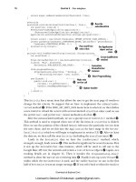
8. If your IP address is to be dynamically assigned by your ISP or the
corporate intranet, select the “TCP/IP Settings” radio button. Next,
select the “Server assigned IP address” radio button. (“Server
assigned name server addresses” should also be selected.)
9. Leave all other defaults as they are.
10. Click “OK” to save your changes and return to the DUN window.
www.syngress.com
Figure 3.13 Selecting PPP in MS dial-up networking.
93_sbcran_Ch03 10/16/00 2:29 PM Page 106
Using PPP To Provide Remote Network Access • Chapter 3 107
Figure 3.14 Selecting DHCP IP address assignment on Windows 98.
Windows NT4 Clients
Windows 95 clients default to a PPP dial-up server when using Microsoft’s
DUN software. To confirm this setting, or to change a manually configured
dial-up connection to PPP, do the following:
1. Double-click the “My Computer” icon on your desktop.
2. Double-click “Dial-up Networking.”
3. Right-click the dial-up connection of interest and select
“Properties.”
4. Select the “Server Types” tab.
5. Under “Type of Dial-Up Server,” select “PPP: Windows NT, Windows
95 Plus, Internet.”
6. Uncheck the “Log on to network” check box (unless dialing into a
Windows server).
7. Select the check boxes of the network protocols you will be using,
such as “TCP/IP.”
www.syngress.com
93_sbcran_Ch03 10/16/00 2:29 PM Page 107
108 Chapter 3 • Using PPP To Provide Remote Network Access
8. Select whether to have DHCP assign your IP address, or assign a
static IP configuration (IP address, mask, default gateway, and so
on).
9. If you need to configure MSCB in NT, select “User Preferences,”
select the “Callback” tab, and select “Yes, call me back at the
number(s) below” and enter your phone number.
Windows 2000 Clients
Windows 2000 clients also default to a PPP dial-up service when using
Microsoft’s DUN software. To confirm this setting, or to change a manually
configured dial-up connection to PPP, do the following (Figures 3.15, 3.16,
and 3.17):
1. Double-click the “My Computer” icon on your Windows 2000
desktop.
Figure 3.15 Windows 2000 dial-up connection properties.
www.syngress.com
93_sbcran_Ch03 10/16/00 2:29 PM Page 108
Using PPP To Provide Remote Network Access • Chapter 3 109
2. Double-click “Network and Dial-up Connections.”
3. Right-click the dial-up connection of interest and select
“Properties.”
4. Select the “Networking” tab.
5. Under “Type of dial-up server I am calling,” select “PPP: Windows
95/98/NT 4/2000, Internet.”
6. To select whether to have DHCP assign your IP address, or to
assign a static IP address, highlight “Internet Protocol (TCP/IP)”
and select the “Properties” button. To use DHCP services, select
the “Obtain an IP address automatically” radio button. To use a
manually assigned IP address, select the “Use the following IP
address” radio button and enter the IP address.
7. To select authentication protocol (such as PAP, CHAP, or MS-
CHAP), select the “Security” tab, and then press the “Advanced
Security Settings” button and check all applicable authentication
protocols.
Figure 3.16 Windows 2000 advanced security settings dialog box.
www.syngress.com
93_sbcran_Ch03 10/16/00 2:29 PM Page 109
110 Chapter 3 • Using PPP To Provide Remote Network Access
Windows 2000 clients use an installation wizard to guide users through
the installation of new dial-up connections. To install a new dial-up
connection, do the following:
1. Double-click the “My Computer” icon.
2. Select “Network and Dial-up Connections.”
3. Select “Make New Connection.”
4. Follow the wizard prompts.
Figure 3.17 Windows 2000 dial-up configuration wizard.
Troubleshooting Microsoft Windows
Connections
To troubleshoot MS Windows connections from the client end, do the fol-
lowing general steps:
1. Make sure that the dial-in line the modem is connected to has a
dial tone.
www.syngress.com
93_sbcran_Ch03 10/16/00 2:29 PM Page 110
Using PPP To Provide Remote Network Access • Chapter 3 111
2. Go to Windows’ “Control Panel” (and/or “Device Manager” in the
“System Panel” for Win95/98) and make sure your modem driver
is installed, your modem is operational, and that it has no conflicts
with other hardware.
3. Check in the “Network” panel and make sure that the proper net-
work protocols are configured (such as TCP/IP) for the dial-up
adapter, and that “Client for Microsoft Windows” or another client
has been installed.
Summary
From our thorough examination of PPP, we can see the reason for its popu-
larity as the de facto standard for remote access networks. It is a reliable,
versatile, secure, and scalable protocol for connecting two point-to-point
devices.
PPP’s LCP and NCP sublayers handle the creation, configuration, and
maintenance of the point-to-point connection. Through LCP frames, the
status of the link is monitored and maintained.
Configuration and negotiation parameters support the use of multiple
network protocols (such as TCP/IP, IPX, and AppleTalk) over the same
communications link. Neither SLIP nor ARAP support more than one native
network protocol.
Another very important part of PPP’s popularity is the authentication of
end-to-end peers using PAP, CHAP, and the technique of PPP Callback.
These authentication methods enhance network security to help ease the
concerns of network administrators and other IT professionals.
Through the use of MP, several communications lines can be bound
together to form a single logical connection between two point-to-point
peers that is transparent to the end user. By using MMP, such “bonds” can
be distributed across several Cisco access servers to distribute dial-in
usage and simplify user access by using only a single telephone number
for all dial-in access. Such usage allows IT departments and ISPs to fully
utilize their dial-in access servers while providing higher bandwidths to
“power users” using current access technologies such as analog dial-in
lines and ISDN services.
All of these benefits are achieved through a protocol that is simple for
network engineers and end users alike to implement, maintain, and use.
www.syngress.com
93_sbcran_Ch03 10/16/00 2:29 PM Page 111
112 Chapter 3 • Using PPP To Provide Remote Network Access
FAQs
Q: Can PPP be used over an ISDN line?
A: Yes. PPP can be used over ISDN and most asynchronous and syn-
chronous communications links.
Q: Does PPP support TCP/IP, IPX, NetBEUI, and AppleTalk?
A: Yes. SLIP supports only TCP/IP, and ARAP supports only AppleTalk.
Q: Can I use PPP over a Frame Relay network?
A: No. Frame Relay is the Layer 2 protocol used on Frame Relay networks.
Q: If I have 10 users dial into my Cisco access router, do they all appear
as different networks for each connection?
A: Yes. PPP treats each connection as a different network, and an associ-
ated entry will be placed into the Cisco access router’s routing table.
Q: Can multiple Cisco access servers be grouped together in a single
rotary group so that all incoming calls go to a single dial-in number?
A: Yes, this grouping of servers is known as MMP. MMP is completely
transparent to the end user.
Q: What version of the Cisco IOS must be used to support MMP?
A: The enterprise j-image of the Cisco IOS. See www.cisco.com/warp/
public/131/6.html
www.syngress.com
93_sbcran_Ch03 10/16/00 2:29 PM Page 112
Utilizing Virtual
Private Network
(VPN) Technology
for Remote Access
Connectivity
Solutions in this chapter:
■
Site-to-site VPN technology
■
Remote access VPN technology
■
Advantages of VPN technology
■
Disadvantages of VPN technology
■
Security
■
Cisco’s VPN solutions
Chapter 4
113
93_sbcran_04 10/16/00 12:40 PM Page 113
114 Chapter 4 • Utilizing VPN Technology for Remote Access Connectivity
Introduction
The term VPN (virtual private network) is a hot term that often pops up
when discussing today’s networking infrastructure technologies. A VPN is
another term for a secure, private network over a public infrastructure like
the Internet. With many companies utilizing a shared office or being faced
with providing network access to traveling users, it is becoming increas-
ingly popular for corporations to provide a VPN solution. It’s as easy as
installing a secure client on employees’ computers, providing them with
public Internet access, and allowing them to dial in to the Internet and
access the same private data that they would if they were locally connected
to their company’s local area network (LAN). There are many cost advan-
tages that make it clear why VPNs are now being implemented over tradi-
tional infrastructures like Frame Relay or Integrated Services Digital
Network (ISDN), but there are also some disadvantages that need to be
reviewed. This chapter walks you through the different types of VPN solu-
tions and describes the important factors to consider when determining
whether a VPN solution is right for your environment.
VPN Technology
VPN technology allows private secure networking over public network
infrastructures. This is done through technology that allows VPN devices to
authenticate their identity, verify the integrity of the data being sent and
received, and optionally, provide for confidentiality of data through encryp-
tion. Today’s VPNs are based on the Internet Security Association and Key
Management Protocol (ISAKMP) and Internet Protocol Security (IPSec) stan-
dards.
ISAKMP & IKE
ISAKMP is a framework for exchanging keys and establishing security
associations. ISAKMP does not negotiate keys, but simply provides for
rules to follow.
Internet Key Exchange (IKE) provides added features, flexibility, and
ease of configuration for the IPSec standard. IKE uses part Skeme and part
Oakley protocols, which follow the ISAKMP framework. IKE is used to
authenticate peers, set up IPSec keys, and negotiate security associations.
A security association is created when two VPN devices decide on what
algorithms and keys to use for key exchange, authenticating, and
encrypting data. Generally, when speaking about ISAKMP and IPSec
together, there are two initial security associations that take place—the
authentication of the devices and IPSec operations.
www.syngress.com
93_sbcran_04 10/16/00 12:40 PM Page 114
www.syngress.com
IPSec
IPSec is a set of protocols used at the network layer to secure data. IPSec
consists of two protocols, Authentication Header (AH) and Encapsulating
Security Payload (ESP).
AH provides protection by placing itself in the header data. The authen-
tication header is used to validate the integrity of the packet, as well as to
validate the origin of the packet. AH can also prevent replay attacks, where
a captured session of data is replayed against a host service. The AH pro-
tocol uses a hash algorithm to provide this data integrity. Using AH, the
receiving peer can be assured that the header information is valid and
originated from the source without intervention. AH can be used alone to
provide authenticated traffic or in combination with ESP to provide
encrypted data.
ESP is the other protocol in the IPSec suite. ESP is used to encrypt the
payload or data in an IP datagram to provide data confidentiality. It encap-
sulates the datagram, whereas AH embeds itself into the datagram. ESP is
also used to validate authenticity of origination and integrity of the data-
gram. ESP provides for data confidentiality through the encryption of the
packet payload; confidentiality can be used with or without the optional
authenticity and integrity parameters. Confidentiality used without
authenticating or validating integrity can allow for certain other forms of
attack, so validation and integrity are recommended in using ESP or AH.
ESP can also be used to prevent replay attacks and to thwart traffic flow
analysis.
Utilizing VPN Technology for Remote Access Connectivity • Chapter 4 115
Skeme and Oakley Protocols
The Oakley protocol describes a series of key exchanges, called modes,
and details the services provided by each (for example, perfect forward
secrecy for keys, identity protection, and authentication). The Skeme
protocol describes a versatile key exchange technique that provides
anonymity, reputability, and quick key refreshment. Their relationship to
ISAKMP is fairly straightforward: where Oakley defines modes of
exchange, ISAKMP defines phases of when each is applied.
For IT Professionals
93_sbcran_04 10/16/00 12:40 PM Page 115
116 Chapter 4 • Utilizing VPN Technology for Remote Access Connectivity
DES, Triple Pass DES & 3DES
The Data Encryption Standard (DES) is a very mature cryptographic
system. The DES algorithm is a complex symmetric algorithm that speci-
fies that data be encrypted in 64 bit blocks. A 64-bit block of clear text
goes into the algorithm along with a 56-bit key; the result is a 64-bit block
of cipher text. Since the key size is fixed at 56-bits, the number of keys
available (the key space) is 256 (about 72,000,000,000,000,000 keys).
Triple pass DES is a cryptographic system that uses multiple passes of
the DES algorithm to increase the effective key space available to the
system. In triple pass DES, the clear text data is first encrypted with a 56-
bit key. The resulting cipher text is then decrypted with a different key. Of
course, decrypting cipher text with the wrong key will result in garbage.
Finally, the garbage is encrypted again with the first key. This implementa-
tion of triple pass DES is known as EDE (for Encrypt, Decrypt, Encrypt),
and the technique increases the effective key length from 56 bits to 112
bits. Ninety-bit keys should protect encrypted data for about 20 years.
3DES is a cryptographic system that uses multiple passes of the DES
algorithm to increase the effective key space available to the system even
further than triple pass DES. The same EDE technique employed in triple
pass DES is used, except that three different keys are used. This increases
the effective key length from 56 bits for simple DES to 168 bits for 3DES
.
The benefit of using 3DES over DES is obvious. The very strong encryp-
tion and security of the key make it the best solution when the highest
security is needed. The drawback to 3DES is its effect on processing. It
takes a lot more processing power to compute such a complex algorithm;
for this reason, vendors have begun selling add-on cards that separate
crypto processing functions from the processor of the VPN device so the
processor can do its normal functions and the add-on card takes the
crypto load off the processor.
VPN Operation
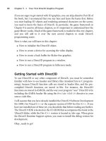
There is often confusion over how IPSec, IKE, and ISAKMP work together
to create a VPN. To sort this out, let’s take a look at the flowchart in Figure
4.1 to see how they operate together to form a VPN tunnel.
As traffic enters the router to be forwarded, it is checked against an
access list associated with the crypto map applied to that particular inter-
face. If the traffic matches the list, the router checks to see if there is an
IPSec security association (IPSec SA) with the peer for this traffic. If there
is, the traffic is encrypted and sent out the interface. If there is no IPSec
SA, the router will check to see if it has an ISAKMP security association
(ISAKMP SA). If it does, then IKE will negotiate IPSec keys and SAs,
www.syngress.com
93_sbcran_04 10/16/00 12:40 PM Page 116
Utilizing VPN Technology for Remote Access Connectivity • Chapter 4 117
encrypt the traffic using IPSec and forward the traffic. If there is no
ISAKMP SA, then IKE will attempt to authenticate the peer and create an
ISAKMP SA; upon successful completion of an ISAKMP SA, IKE will nego-
tiate an IPSec SA, encrypt the data, and forward the traffic. IKE uses the
Skeme and Oakley protocols inside the ISAKMP framework, so that when
we are using IKE to negotiate keys and security associations, it is oper-
ating within ISAKMP.
Cisco VPN Terminology
Here are some of the terms used in the world of Cisco VPN technology.
Make sure you know what they mean before reading on.
www.syngress.com
Figure 4.1 The interaction among IPSec, IKE, and ISAKMP.
Send traffic out
interface
No
Is there an IPSec
security association
for this traffic?
Yes
Encrypt and
forward
Yes
Use IKE (inside
ISAKMP) to
negotiate an IPSec
SA
No
Yes
No
Bad Authentication
Traffic is dropped
Traffic matches list for
encryption?
Traffic
Has IKE negotiated
ISAKMP keys
and SA?
Authenticate peer and
negotiate ISAKMP SA
Good Authentication and SA
93_sbcran_04 10/16/00 12:40 PM Page 117
118 Chapter 4 • Utilizing VPN Technology for Remote Access Connectivity
Peer The “other side,” or the other router that will be doing encryption. It
takes at least two encryption devices to make a VPN, and each one is the
peer of the other.
Transform-Set Used to define the IPSec protocols you want to use for
authentication and/or encryption.
Crypto Map Used to tie together configurations such as the transform set,
the peer, and the data to be encrypted.
Dynamic Crypto Map A crypto map before some of the information is
provided by the remote peer.
ISAKMP (Internet Security Association and Key Management Protocol)
Framework providing a means for policy negotiations and key management.
IKE (Internet Key Exchange) Uses parts of the ISAKMP framework to
authenticate peers and negotiate IPSec keys and security associations.
ESP (Encapsulating Security Payload) Used as the method to encrypt the
packet payload and/or authentication packets.
DES (Data Encryption Standard) Uses a 56-bit encrypting algorithm to
encrypt data.
3DES (Triple Data Encryption Standard) Uses a 168-bit encrypting algo-
rithm to encrypt data.
MD5 (Message Digest 5) A hash algorithm used to hash keys and pass the
hash instead of passing the key or password.
SHA (Secure Hash Algorithm) Another hash algorithm used to hash keys
and pass the hash instead of passing the key or password.
NOTE
Hashing is the process of running a password or shared key through an
algorithm to come up with a string of numbers representing the key or
password. This is then sent to the peer, as opposed to sending the key or
password itself. The other side then de-hashes the key or password and
checks it against its own database entry for the password or key. If the
de-hashed string matches what the router has in its configuration, it is a
good match. MD5 uses a 128-bit hash and SHA uses a 168-bit hash.
Parallel processing on an MD5 hashed key is not possible.
VPNs can take different forms; a VPN can be created between two com-
puters, a computer and a network, or a network and a network. VPNs
www.syngress.com
93_sbcran_04 10/16/00 12:40 PM Page 118
Utilizing VPN Technology for Remote Access Connectivity • Chapter 4 119
between a single computer and a network sometimes use client software
installed on the machine to create a VPN tunnel between the computer and
the device that connects to the network, such as a router—or in the case of
an extranet, a firewall. In most enterprise scenarios the VPN tunnel is not
actually created from the end computer to the remote end computer, but
rather between two intermediary devices that sit between the computers or
networks (such as routers, VPN concentrators, or firewalls). The IPSec
standards have allowed various devices and software to interoperate when
forming VPNs.
Site-to-Site VPN
Here we will begin exploring the various types of VPN scenarios. As stated
earlier, a VPN in the enterprise is usually not created between two end
host systems but rather the intermediary devices that connect the net-
work. We will look at the various intermediary devices such as the Cisco
router and the PIX Firewall, and how they are configured to form VPN tun-
nels. Later in the chapter we will also look at how to create VPN tunnels
from client to intermediary device using software installed on the client
system.
An Intranet Solution
In this section we will walk through several different scenarios in securing
communication between a branch office and the corporate network. Let’s
begin by exploring the networks in Figure 4.2. First, look at the corporate
network. On the corporate LAN are the accounting, research, engineering,
and e-mail servers, which service both the corporate users and the branch
office. The corporate network in this example is a 10.2.2.0 subnet, and is
connected to the branch office through the 192.168.5.2 interface on the
Central router. The branch office is subnet 10.2.3.0, which consists of a
small sales force and customer services department, connected to
Corporate through the Branch router on the 192.168.5.1 interface.
By utilizing VPN technology, we can secure communications between
all of the corporate networks and all branch office networks, or a single
host and the networks. In this scenario we will secure all communications
between the networks by terminating VPN tunnels on the outside inter-
faces of both Branch and Corporate routers, and defining that all traffic
between them gets encrypted. This is done in access lists based on source
addresses, or networks and destination addresses, or networks. Let’s begin
by taking a look at how we configure ISAKMP and IKE to facilitate key
management and exchange.
www.syngress.com
93_sbcran_04 10/16/00 12:40 PM Page 119
120 Chapter 4 • Utilizing VPN Technology for Remote Access Connectivity
Configuring ISAKMP/IKE
The first thing we will want to look at is how we configure ISAKMP policy
to define security parameters to be used in Internet Key Exchange negotia-
tion. It is possible to have several ISAKMP policies facilitate communica-
tions between peers requiring different encryption and hashing schemes;
therefore, we assign a policy number to each of our ISAKMP policies. A
peer must match one of the configured policies to begin negotiating the
security association (SA). If there is no policy match, no SA is created and
hence no VPN tunnel. Let’s start by looking at the configuration of the
Central router.
We need to define an ISAKMP policy. We use a policy number to assign
commands specific to this configuration to an ISAKMP policy. If we had
multiple peers and needed a different policy for each peer, we would simply
add additional policies with different policy numbers. The lowest policy
number takes precedence. For our config, we only need the single policy.
Central(config)# crypto isakmp policy 100
Next we need to decide what type of encryption we want to use for data
confidentiality. We will use 56-bit data encryption standard (DES). Notice
that the router prompt has changed. All configuration commands for
ISAKMP from here on are part of policy 100.
Central(config-isakmp)# encryption des
www.syngress.com
Figure 4.2 Corporate to branch office VPN.
Sales
Server
Sales
Workstation
Workgroup
Server
Customer
Service
Accounting
Server
Research
Server
Engineering
Corp E-Mail
Corporate
Branch
HQ
Workstation
RouterB
192.168.5.1
RouterA
192.168.5.2
10.2.2.0 Subnet
10.2.3.0 Subnet
HQ
Workstation
HQ
Workstation
HQ
Workstation
HQ
Workstation
HQ
Workstation
Sales
Workstation
Sales
Workstation
Customer
Service
Customer
Service
93_sbcran_04 10/16/00 12:40 PM Page 120
Utilizing VPN Technology for Remote Access Connectivity • Chapter 4 121
Define which hash algorithm to use. This could be MD5 or SHA.
Central(config-isakmp)# hash md5
Now we define the method the two routers will use to authenticate each
other. This can be done with pre-shared keys or using digital certificates.
In our configuration we will use pre-shared keys.
Central(config-isakmp)# authentication pre-share
Specify the Diffie-Hellman 768-bit group identifier.
Central(config-isakmp)# group 1
When using pre-shared keys it is also necessary to define the identity
of each peer. The identity can be the hostname or its IP address. The
default is to use IP addresses for peer identity. We will specify that we want
to use the ip address to identify our peer.
Central(config)# crypto isakmp identity address
Specify the pre-shared key and the identity (the IP address) of our
encryption peer. The key will need to be the same on both ends.
Central(config-isakmp)# crypto isakmp key secretkey address 192.168.5.1
Verify the ISAKMP configuration.
Central router# show crypto isakmp policy
Issuing the show crypto isakmp policy command allows you to verify
that the router is using the information that you entered for its configura-
tion, and to quickly check the parameters of ISAKMP without having to
read through the whole configuration of the device.
Protection suite of priority 100
encryption algorithm: DES - Data Encryption Standard (56 bit keys).
hash algorithm: Message Digest 5
Authentication method: Pre-Shared Key
Diffie-Hellman group: #1 (768 bit)
Lifetime: 86400 seconds, no volume limit
Default protection suite
encryption algorithm: DES - Data Encryption Standard (56 bit keys).
hash algorithm: Secure Hash Standard
authentication method: Rivest-Shamir-Adleman Signature
Diffie-Hellman group: #1 (768 bit)
lifetime: 86400 seconds, no volume limit
www.syngress.com
93_sbcran_04 10/16/00 12:40 PM Page 121