cisco 640 802 ccna portable command guide 2008 phần 10 pdf
Bạn đang xem bản rút gọn của tài liệu. Xem và tải ngay bản đầy đủ của tài liệu tại đây (376.26 KB, 33 trang )
Restoring the Cisco IOS Software from ROM Monitor Mode Using Xmodem 191
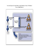
Figure 16-1 Finding the Cisco IOS Software Image File
Do you wish to continue? y/n [n ]:yy
yy
Choose y to continue.
In HyperTerminal, go to Transfer,
then Send File (see Figure 16-1).
Locate the Cisco IOS Software file
on the hard drive and click Send
(see Figure 16-2).
Router will reload when transfer is completed.
Reset baud rate on router.
Router(config)#ll
ll
ii
ii
nn
nn
ee
ee
cc
cc
oo
oo
nn
nn
00
00
Router(config-line)#ss
ss
pp
pp
ee
ee
ee
ee
dd
dd
99
99
66
66
00
00
00
00
Router(config-line)#ee
ee
xx
xx
ii
ii
tt
tt
HyperTerminal will stop
responding. Reconnect to the router
using 9600 baud, 8-N-1.
192 Restoring IOS software using tftpdnld
Figure 16-2 Sending the Cisco IOS Software Image File to the Router
Restoring the Cisco IOS Software Using the ROM Monitor
Environmental Variables and tftpdnld Command
NOTE: Commands and environmental variables are case sensitive, so be sure
that you have not accidentally added spaces between variables and answers.
rommon 1>II
II
PP
PP
__
__
AA
AA
DD
DD
DD
DD
RR
RR
EE
EE
SS
SS
SS
SS
==
==
11
11
99
99
22
22
11
11
66
66
88
88
11
11
00
00
00
00
11
11
Indicates the IP address for this
unit.
rommon 2>II
II
PP
PP
__
__
SS
SS
UU
UU
BB
BB
NN
NN
EE
EE
TT
TT
__
__
MM
MM
AA
AA
SS
SS
KK
KK
==
==
22
22
55
55
55
55
22
22
55
55
55
55
22
22
55
55
55
55
00
00
Indicates the subnet mask for this
unit.
rommon 3>DD
DD
EE
EE
FF
FF
AA
AA
UU
UU
LL
LL
TT
TT
__
__
GG
GG
AA
AA
TT
TT
EE
EE
WW
WW
AA
AA
YY
YY
==
==
11
11
99
99
22
22
11
11
66
66
88
88
11
11
00
00
00
00
11
11
Indicates the default gateway for
this unit.
rommon 4>TT
TT
FF
FF
TT
TT
PP
PP
__
__
SS
SS
EE
EE
RR
RR
VV
VV
EE
EE
RR
RR
==
==
11
11
99
99
22
22
11
11
66
66
88
88
11
11
00
00
00
00
22
22
Indicates the IP address of the
TFTP server.
rommon 5>TT
TT
FF
FF
TT
TT
PP
PP
__
__
FF
FF
II
II
LL
LL
EE
EE
==
==
cc
cc
22
22
66
66
00
00
00
00
jj
jj
ss
ss
ll
ll
__
__
11
11
22
22
11
11
33
33
bb
bb
ii
ii
nn
nn
Indicates the filename to fetch
from the TFTP server.
rommon 6>tt
tt
ff
ff
tt
tt
pp
pp
dd
dd
nn
nn
ll
ll
dd
dd
Starts the process.
…<output cut>…
Do you wish to continue? y/n: [n]:yy
yy
…<output cut>…
Rommon 7>ii
ii
Resets the router. The i stands for
initialize.
CHAPTER 17
Password-Recovery
Procedures and the
Configuration Register
This chapter provides information and commands concerning the following topics:
• The configuration register
— A visual representation
— What the bits mean
— The boot field
— Console terminal baud rate settings
— Changing the console line speed: CLI
— Changing the console line speed: ROM Monitor mode
• Password-recovery procedures for Cisco routers
• Password-recovery procedures for 2960 series switches
The Configuration Register
A Visual Representation
The configuration register is a 16-bit field stored in NVRAM. The bits are numbered
from 15 to 0 looking at the bit stream from left to right. Bits are split up into groups
of 4, and each group is represented by a hexadecimal digit.
router#ss
ss
hh
hh
oo
oo
ww
ww
vv
vv
ee
ee
rr
rr
ss
ss
ii
ii
oo
oo
nn
nn
The last line of output tells you what
the configuration register is set to.
router#cc
cc
oo
oo
nn
nn
ff
ff
ii
ii
gg
gg
uu
uu
rr
rr
ee
ee
tt
tt
ee
ee
rr
rr
mm
mm
ii
ii
nn
nn
aa
aa
ll
ll
Moves to global configuration mode.
router(config)#cc
cc
oo
oo
nn
nn
ff
ff
ii
ii
gg
gg
rr
rr
ee
ee
gg
gg
ii
ii
ss
ss
tt
tt
ee
ee
rr
rr
00
00
xx
xx
22
22
11
11
44
44
22
22
Changes the configuration register
to 2142.
15 14 13 12 11 10 9 8 7 6 5 4 3 2 1 0 Bit places
0 0 1 0 0 0 0 1 0 1a 0 0 0 0 1 0 Register bits
2 1 4 2 Bits represented in hex
194 The Configuration Register
What the Bits Mean
The Boot Field
NOTE: Even though there are 16 possible combinations in the boot field, only
3 are used.
TIP: Because the default boot field has 14 different ways to represent it, a
configuration register setting of 0x2102 is the same as 0x2109, or 210F. The boot
system command is described in Chapter 16, “Backing Up and Restoring Cisco
IOS Software and Configurations.”
Bit Number Hexadecimal Meaning
00–03 0x0000–0x000F Boot field.
06 0x0040 Ignore NVRAM contents.
07 0x0080 OEM bit enabled.
08 0x0100 Break disabled.
09 0x0200 Causes system to use secondary bootstrap
(typically not used).
10 0x0400 IP broadcast with all 0s.
5, 11, 12 0x0020, 0x0800,
0x1000
Console line speed.
13 0x2000 Boots default ROM software if network boot fails.
14 0x4000 IP broadcasts do not have net numbers.
15 0x8000 Enables diagnostic messages and ignores NVRAM
contents.
Boot Field Meaning
00 Stays at the ROM Monitor on a reload or power cycle
01 Boots the first image in flash memory as a system image
02–F Enables default booting from flash memory
Enables boot system commands that override default booting from
flash memory
The Configuration Register 195
Console Terminal Baud Rate Settings
Changing the Console Line Speed: CLI
TIP: Cisco IOS Software does not allow you to change the console speed bits
directly with the config-register command.
Changing the Console Line Speed: ROM Monitor Mode
Baud Bit 5 Bit 12 Bit 11
115200 1 1 1
57600 1 1 0
38400 1 0 1
19200 1 0 0
9600 0 0 0
4800 0 0 1
2400 0 1 1
1200 0 1 0
router#cc
cc
oo
oo
nn
nn
ff
ff
ii
ii
gg
gg
uu
uu
rr
rr
ee
ee
tt
tt
ee
ee
rr
rr
mm
mm
ii
ii
nn
nn
aa
aa
ll
ll
router(config)#ll
ll
ii
ii
nn
nn
ee
ee
cc
cc
oo
oo
nn
nn
ss
ss
oo
oo
ll
ll
ee
ee
00
00
Enters console line mode
router(config-line)#ss
ss
pp
pp
ee
ee
ee
ee
dd
dd
11
11
99
99
22
22
00
00
00
00
Changes speed to 19200 baud
rommon1>cc
cc
oo
oo
nn
nn
ff
ff
rr
rr
ee
ee
gg
gg
Shows configuration
summary. Step through
the questions,
answering with the
defaults until you can
change the console
baud rate.
Configuration Summary
enabled are:
load rom after netboot fails
console baud: 9600
boot: image specified by the boot system commands
or default to:
x
(name of system image)
196 Password-Recovery Procedures for Cisco Routers
TIP: Make sure that after you change the console baud rate, you change your
terminal program to match the same rate!
Password-Recovery Procedures for Cisco Routers
do you wish to change the configuration? y/n [n]: yy
yy
enable “diagonstic mode”? y/n [n]: nn
nn
enable “use net in IP bcast address”? y/n [n]: nn
nn
disable “load rom after netboot fails”? y/n [n]: nn
nn
enable “use all zero broadcast”? y/n [n]: nn
nn
enable “break/abort has effect”? y/n [n]: nn
nn
enable “ignore system config info”? y/n [n]: nn
nn
change console baud rate? y/n [n]: yy
yy
enter rate: 0=9600, 1=4800, 2=1200, 3=2400
4=19200, 5=38400, 6=57600, 7=115200
[0]: 77
77
Configuration Summary
enabled are:
load rom after netboot fails
console baud: 115200
boot: image specified by the boot system commands
or default to:
x
(name of system image)
change the boot characteristics? y/n [n]: nn
nn
After the summary is
shown again, choose n
to not change the
configuration and go to
the rommon>prompt
again.
rommon2>
Step 2500 Series Commands
1700/2600/ISR Series
Commands
Step 1: Boot the router
and interrupt the boot
sequence as soon as text
appears on the screen.
Press Ç-ı
>
Press Ç-ı
rommon 1>
Password-Recovery Procedures for Cisco Routers 197
Step 2: Change the
configuration register to
ignore contents of
NVRAM.
>oo
oo
//
//
rr
rr
00
00
xx
xx
22
22
11
11
44
44
22
22
rommon 1>cc
cc
oo
oo
nn
nn
ff
ff
rr
rr
ee
ee
gg
gg
00
00
xx
xx
22
22
11
11
44
44
22
22
> rommon 2>
Step 3: Reload the router.
>ii
ii
rommon 2>rr
rr
ee
ee
ss
ss
ee
ee
tt
tt
Step 4: Enter privileged
mode. (Do not enter setup
mode.)
Router>ee
ee
nn
nn
aa
aa
bb
bb
ll
ll
ee
ee
Router>ee
ee
nn
nn
aa
aa
bb
bb
ll
ll
ee
ee
Router# Router#
Step 5: Copy the startup
configuration into the
running configuration.
Router#cc
cc
oo
oo
pp
pp
yy
yy
ss
ss
tt
tt
aa
aa
rr
rr
tt
tt
uu
uu
pp
pp
cc
cc
oo
oo
nn
nn
ff
ff
ii
ii
gg
gg
rr
rr
uu
uu
nn
nn
nn
nn
ii
ii
nn
nn
gg
gg
cc
cc
oo
oo
nn
nn
ff
ff
ii
ii
gg
gg
Router#cc
cc
oo
oo
pp
pp
yy
yy
ss
ss
tt
tt
aa
aa
rr
rr
tt
tt
uu
uu
pp
pp
cc
cc
oo
oo
nn
nn
ff
ff
ii
ii
gg
gg
rr
rr
uu
uu
nn
nn
nn
nn
ii
ii
nn
nn
gg
gg
cc
cc
oo
oo
nn
nn
ff
ff
ii
ii
gg
gg
…<output cut>… …<output cut>…
Denver# Denver#
Step 6: Change the
password.
Denver#cc
cc
oo
oo
nn
nn
ff
ff
ii
ii
gg
gg
uu
uu
rr
rr
ee
ee
tt
tt
ee
ee
rr
rr
mm
mm
ii
ii
nn
nn
aa
aa
ll
ll
Denver#cc
cc
oo
oo
nn
nn
ff
ff
ii
ii
gg
gg
uu
uu
rr
rr
ee
ee
tt
tt
ee
ee
rr
rr
mm
mm
ii
ii
nn
nn
aa
aa
ll
ll
Denver(config)#ee
ee
nn
nn
aa
aa
bb
bb
ll
ll
ee
ee
ss
ss
ee
ee
cc
cc
rr
rr
ee
ee
tt
tt
new
Denver(config)#ee
ee
nn
nn
aa
aa
bb
bb
ll
ll
ee
ee
ss
ss
ee
ee
cc
cc
rr
rr
ee
ee
tt
tt
new
Denver(config)# Denver(config)#
Step 7: Reset the
configuration register back
to its default value.
Denver(config)#cc
cc
oo
oo
nn
nn
ff
ff
ii
ii
gg
gg
rr
rr
ee
ee
gg
gg
ii
ii
ss
ss
tt
tt
ee
ee
rr
rr
00
00
xx
xx
22
22
11
11
00
00
22
22
Denver(config)#cc
cc
oo
oo
nn
nn
ff
ff
ii
ii
gg
gg
rr
rr
ee
ee
gg
gg
ii
ii
ss
ss
tt
tt
ee
ee
rr
rr
00
00
xx
xx
22
22
11
11
00
00
22
22
Denver(config)# Denver(config)#
Step 8: Save the
configuration.
Denver(config)#ee
ee
xx
xx
ii
ii
tt
tt
Denver(config)#ee
ee
xx
xx
ii
ii
tt
tt
Denver#cc
cc
oo
oo
pp
pp
yy
yy
rr
rr
uu
uu
nn
nn
nn
nn
ii
ii
nn
nn
gg
gg
cc
cc
oo
oo
nn
nn
ff
ff
ii
ii
gg
gg
ss
ss
tt
tt
aa
aa
rr
rr
tt
tt
uu
uu
pp
pp
cc
cc
oo
oo
nn
nn
ff
ff
ii
ii
gg
gg
Denver#cc
cc
oo
oo
pp
pp
yy
yy
rr
rr
uu
uu
nn
nn
nn
nn
ii
ii
nn
nn
gg
gg
cc
cc
oo
oo
nn
nn
ff
ff
ii
ii
gg
gg
ss
ss
tt
tt
aa
aa
rr
rr
tt
tt
uu
uu
pp
pp
cc
cc
oo
oo
nn
nn
ff
ff
ii
ii
gg
gg
Denver# Denver#
198 Password Recovery for 2960 Series Switches
Password Recovery for 2960 Series Switches
Step 9: Verify the
configuration register.
Denver#ss
ss
hh
hh
oo
oo
ww
ww
vv
vv
ee
ee
rr
rr
ss
ss
ii
ii
oo
oo
nn
nn
Denver#ss
ss
hh
hh
oo
oo
ww
ww
vv
vv
ee
ee
rr
rr
ss
ss
ii
ii
oo
oo
nn
nn
…<output cut>… …<output cut>…
Configuration register
is 0x2142 (will be
0x2102 at next reload)
Configuration register
is 0x2142 (will be
0x2102 at next reload)
Denver# Denver#
Step 10: Reload the router.
Denver#rr
rr
ee
ee
ll
ll
oo
oo
aa
aa
dd
dd
Denver#rr
rr
ee
ee
ll
ll
oo
oo
aa
aa
dd
dd
Unplug the power supply from the back of the switch.
Press and hold the Mode button on the front of the
switch.
Plug the switch back in.
Release the Mode button when the SYST LED blinks
amber and then turns solid green. When you release
the Mode button, the SYST LED blinks green.
Issue the following commands:
switch: ff
ff
ll
ll
aa
aa
ss
ss
hh
hh
__
__
ii
ii
nn
nn
ii
ii
tt
tt
Initializes the flash memory.
switch: ll
ll
oo
oo
aa
aa
dd
dd
__
__
hh
hh
ee
ee
ll
ll
pp
pp
ee
ee
rr
rr
switch: dd
dd
ii
ii
rr
rr
ff
ff
ll
ll
aa
aa
ss
ss
hh
hh
::
::
Do not forget the colon. This
displays which files are in flash
memory.
switch: rr
rr
ee
ee
nn
nn
aa
aa
mm
mm
ee
ee
ff
ff
ll
ll
aa
aa
ss
ss
hh
hh
::
::
cc
cc
oo
oo
nn
nn
ff
ff
ii
ii
gg
gg
tt
tt
ee
ee
xx
xx
tt
tt
ff
ff
ll
ll
aa
aa
ss
ss
hh
hh
::
::
cc
cc
oo
oo
nn
nn
ff
ff
ii
ii
gg
gg
oo
oo
ll
ll
dd
dd
You are renaming the
configuration file. The
config.text file contains the
password.
switch: bb
bb
oo
oo
oo
oo
tt
tt
Boots the switch.
Password Recovery for 2960 Series Switches 199
When asked whether you want to enter the
configuration dialog, enter n to exit out to the switch
prompt.
Takes you to user mode.
switch>ee
ee
nn
nn
aa
aa
bb
bb
ll
ll
ee
ee
Enters privileged mode.
switch#rr
rr
ee
ee
nn
nn
aa
aa
mm
mm
ee
ee
ff
ff
ll
ll
aa
aa
ss
ss
hh
hh
::
::
cc
cc
oo
oo
nn
nn
ff
ff
ii
ii
gg
gg
oo
oo
ll
ll
dd
dd
ff
ff
ll
ll
aa
aa
ss
ss
hh
hh
::
::
cc
cc
oo
oo
nn
nn
ff
ff
ii
ii
gg
gg
tt
tt
ee
ee
xx
xx
tt
tt
Renames the configuration file
back to the original name.
Destination filename [config.text]
Press ®.
switch#cc
cc
oo
oo
pp
pp
yy
yy
ff
ff
ll
ll
aa
aa
ss
ss
hh
hh
::
::
cc
cc
oo
oo
nn
nn
ff
ff
ii
ii
gg
gg
tt
tt
ee
ee
xx
xx
tt
tt
ss
ss
yy
yy
ss
ss
tt
tt
ee
ee
mm
mm
::
::
rr
rr
uu
uu
nn
nn
nn
nn
ii
ii
nn
nn
gg
gg
cc
cc
oo
oo
nn
nn
ff
ff
ii
ii
gg
gg
Copies the configuration file
into memory.
768 bytes copied in 0.624 seconds
2960Switch#
The configuration file is now
reloaded. Notice the new
prompt.
2960Switch#cc
cc
oo
oo
nn
nn
ff
ff
ii
ii
gg
gg
uu
uu
rr
rr
ee
ee
tt
tt
ee
ee
rr
rr
mm
mm
ii
ii
nn
nn
aa
aa
ll
ll
Enters global configuration
mode.
2960Switch(config)#
Proceed to change the passwords as needed
2900Switch(config)#ee
ee
xx
xx
ii
ii
tt
tt
2900Switch#cc
cc
oo
oo
pp
pp
yy
yy
rr
rr
uu
uu
nn
nn
nn
nn
ii
ii
nn
nn
gg
gg
cc
cc
oo
oo
nn
nn
ff
ff
ii
ii
gg
gg
ss
ss
tt
tt
aa
aa
rr
rr
tt
tt
uu
uu
pp
pp
cc
cc
oo
oo
nn
nn
ff
ff
ii
ii
gg
gg
Saves the configuration into
NVRAM with new passwords.
This page intentionally left blank
CHAPTER 18
Cisco Discovery
Protocol (CDP)
This chapter provides information and commands concerning the following topic:
• Cisco Discovery Protocol (CDP)
Cisco Discovery Protocol
Router#ss
ss
hh
hh
oo
oo
ww
ww
cc
cc
dd
dd
pp
pp
Displays global CDP information
(such as timers)
Router#ss
ss
hh
hh
oo
oo
ww
ww
cc
cc
dd
dd
pp
pp
nn
nn
ee
ee
ii
ii
gg
gg
hh
hh
bb
bb
oo
oo
rr
rr
ss
ss
Displays information about neighbors
Router#ss
ss
hh
hh
oo
oo
ww
ww
cc
cc
dd
dd
pp
pp
nn
nn
ee
ee
ii
ii
gg
gg
hh
hh
bb
bb
oo
oo
rr
rr
ss
ss
dd
dd
ee
ee
tt
tt
aa
aa
ii
ii
ll
ll
Displays more detail about the
neighbor device
Router#ss
ss
hh
hh
oo
oo
ww
ww
cc
cc
dd
dd
pp
pp
ee
ee
nn
nn
tt
tt
rr
rr
yy
yy
ww
ww
oo
oo
rr
rr
dd
dd
Displays information about the device
named word
Router#ss
ss
hh
hh
oo
oo
ww
ww
cc
cc
dd
dd
pp
pp
ee
ee
nn
nn
tt
tt
rr
rr
yy
yy
**
**
Displays information about all devices
Router#ss
ss
hh
hh
oo
oo
ww
ww
cc
cc
dd
dd
pp
pp
ii
ii
nn
nn
tt
tt
ee
ee
rr
rr
ff
ff
aa
aa
cc
cc
ee
ee
Displays information about interfaces
that have CDP running
Router#ss
ss
hh
hh
oo
oo
ww
ww
cc
cc
dd
dd
pp
pp
ii
ii
nn
nn
tt
tt
ee
ee
rr
rr
ff
ff
aa
aa
cc
cc
ee
ee
x
Displays information about specific
interface x running CDP
Router#ss
ss
hh
hh
oo
oo
ww
ww
cc
cc
dd
dd
pp
pp
tt
tt
rr
rr
aa
aa
ff
ff
ff
ff
ii
ii
cc
cc
Displays traffic information—packets
in/out/version
Router(config)#cc
cc
dd
dd
pp
pp
hh
hh
oo
oo
ll
ll
dd
dd
tt
tt
ii
ii
mm
mm
ee
ee
x
Changes the length of time to keep
CDP packets
Router(config)#cc
cc
dd
dd
pp
pp
tt
tt
ii
ii
mm
mm
ee
ee
rr
rr
x
Changes how often CDP updates are
sent
Router(config)#cc
cc
dd
dd
pp
pp
rr
rr
uu
uu
nn
nn
Enables CDP globally (on by default)
Router(config)#nn
nn
oo
oo
cc
cc
dd
dd
pp
pp
rr
rr
uu
uu
nn
nn
Turns off CDP globally
Router(config-if)#cc
cc
dd
dd
pp
pp
ee
ee
nn
nn
aa
aa
bb
bb
ll
ll
ee
ee
Enables CDP on a specific interface
202 Cisco Discovery Protocol
CAUTION: Although CDP is necessary for some management applications, CDP
should still be disabled in some instances.
Disable CDP globally if
• CDP is not required at all.
• The device is located in an insecure environment.
Use the command no cdp run to disable CDP globally:
RouterOrSwitch(config)#nn
nn
oo
oo
cc
cc
dd
dd
pp
pp
rr
rr
uu
uu
nn
nn
Disable CDP on any interface if
• Management is not being performed.
• The switch interface is a nontrunk interface.
• The interface is connected to a nontrusted network.
Use the interface configuration command no cdp enable to disable CDP on a
specific interface:
RouterOrSwitch(config)#ii
ii
nn
nn
tt
tt
ee
ee
rr
rr
ff
ff
aa
aa
cc
cc
ee
ee
ff
ff
aa
aa
ss
ss
tt
tt
ee
ee
tt
tt
hh
hh
ee
ee
rr
rr
nn
nn
ee
ee
tt
tt
00
00
//
//
11
11
RouterOrSwitch(config-if)#nn
nn
oo
oo
cc
cc
dd
dd
pp
pp
ee
ee
nn
nn
aa
aa
bb
bb
ll
ll
ee
ee
Router(config-if)#nn
nn
oo
oo
cc
cc
dd
dd
pp
pp
ee
ee
nn
nn
aa
aa
bb
bb
ll
ll
ee
ee
Turns off CDP on a specific interface
Router#cc
cc
ll
ll
ee
ee
aa
aa
rr
rr
cc
cc
dd
dd
pp
pp
cc
cc
oo
oo
uu
uu
nn
nn
tt
tt
ee
ee
rr
rr
ss
ss
Resets traffic counters to 0
Router#cc
cc
ll
ll
ee
ee
aa
aa
rr
rr
cc
cc
dd
dd
pp
pp
tt
tt
aa
aa
bb
bb
ll
ll
ee
ee
Deletes the CDP table
Router#dd
dd
ee
ee
bb
bb
uu
uu
gg
gg
cc
cc
dd
dd
pp
pp
aa
aa
dd
dd
jj
jj
aa
aa
cc
cc
ee
ee
nn
nn
cc
cc
yy
yy
Monitors CDP neighbor information
Router#dd
dd
ee
ee
bb
bb
uu
uu
gg
gg
cc
cc
dd
dd
pp
pp
ee
ee
vv
vv
ee
ee
nn
nn
tt
tt
ss
ss
Monitors all CDP events
Router#dd
dd
ee
ee
bb
bb
uu
uu
gg
gg
cc
cc
dd
dd
pp
pp
ii
ii
pp
pp
Monitors CDP events specifically
for IP
Router#dd
dd
ee
ee
bb
bb
uu
uu
gg
gg
cc
cc
dd
dd
pp
pp
pp
pp
aa
aa
cc
cc
kk
kk
ee
ee
tt
tt
ss
ss
Monitors CDP packet-related
information
CHAPTER 19
Telnet and SSH
This chapter provides information and commands concerning the following topics:
• Using Telnet to remotely connect to other devices
• Configuring the Secure Shell Protocol (SSH)
Using Telnet to Remotely Connect to Other Devices
The following five commands all achieve the same result: the attempt to connect
remotely to the router named Paris at IP address 172.16.20.1.
Any of the preceding commands lead to the following configuration sequence:
Denver>tt
tt
ee
ee
ll
ll
nn
nn
ee
ee
tt
tt
pp
pp
aa
aa
rr
rr
ii
ii
ss
ss
Enter if ip host command was used previously
to create a mapping of an IP address to the
word paris.
Denver>tt
tt
ee
ee
ll
ll
nn
nn
ee
ee
tt
tt
11
11
77
77
22
22
11
11
66
66
22
22
00
00
11
11
Denver>pp
pp
aa
aa
rr
rr
ii
ii
ss
ss
Enter if ip host command is using default
port #.
Denver>cc
cc
oo
oo
nn
nn
nn
nn
ee
ee
cc
cc
tt
tt
pp
pp
aa
aa
rr
rr
ii
ii
ss
ss
Denver>11
11
77
77
22
22
11
11
66
66
22
22
00
00
11
11
Paris>
As long as vty password is set. See the
Caution following this table.
Paris>ee
ee
xx
xx
ii
ii
tt
tt
Terminates the Telnet session and returns
you to the Denver prompt.
Denver>
Paris>ll
ll
oo
oo
gg
gg
oo
oo
uu
uu
tt
tt
Terminates the Telnet session and returns
you to the Denver prompt.
204 Using Telnet to Remotely Connect to Other Devices
CAUTION: The following configuration creates a big security hole. Never use it
in a live production environment. Use it in the lab only!
Denver>
Paris> Ç-Í-6,
release, then press x
Suspends the Telnet session but does not
terminate it, and returns you to the Denver
prompt.
Denver>
Denver>®
Resumes the connection to Paris.
Paris>
Denver>rr
rr
ee
ee
ss
ss
uu
uu
mm
mm
ee
ee
Resumes the connection to Paris.
Paris>
Denver>dd
dd
ii
ii
ss
ss
cc
cc
oo
oo
nn
nn
nn
nn
ee
ee
cc
cc
tt
tt
pp
pp
aa
aa
rr
rr
ii
ii
ss
ss
Terminates the session to Paris.
Denver>
Denver#ss
ss
hh
hh
oo
oo
ww
ww
ss
ss
ee
ee
ss
ss
ss
ss
ii
ii
oo
oo
nn
nn
ss
ss
Displays connections you opened to other
sites.
Denver#ss
ss
hh
hh
oo
oo
ww
ww
uu
uu
ss
ss
ee
ee
rr
rr
ss
ss
Displays who is connected remotely to you.
Denver#cc
cc
ll
ll
ee
ee
aa
aa
rr
rr
ll
ll
ii
ii
nn
nn
ee
ee
x
Disconnects the remote user connected to
you on line x.
The line number is listed in the output
gained from the show users command.
Denver(config)#ll
ll
ii
ii
nn
nn
ee
ee
vv
vv
tt
tt
yy
yy
00
00
44
44
Moves to line configuration mode for vty
lines 0–4.
Denver(config-line)
ss
ss
ee
ee
ss
ss
ss
ss
ii
ii
oo
oo
nn
nn
ll
ll
ii
ii
mm
mm
ii
ii
tt
tt
x
Limits the number of simultaneous sessions
per vty line to x number.
Configuring the Secure Shell Protocol (SSH) 205
NOTE: A device must have two passwords for a remote user to be able to make
changes to your configuration:
• Line vty password (or have it explicitly turned off; see the preceding Caution)
• Enable or enable secret password
Without the enable or enable secret password, a remote user will only be able to
get to user mode, not to privileged mode. This is extra security.
Configuring the Secure Shell Protocol (SSH)
CAUTION: SSH Version 1 implementations have known security issues. It is rec-
ommended to use SSH Version 2 whenever possible.
NOTE: To work, SSH requires a local username database, a local IP domain, and
an RSA key to be generated.
The Cisco implementation of SSH requires Cisco IOS Software to support Rivest-
Shamir-Adleman (RSA) authentication and minimum Data Encryption Standard
(DES) encryption—a cryptographic software image.
Denver(config)#ll
ll
ii
ii
nn
nn
ee
ee
vv
vv
tt
tt
yy
yy
00
00
44
44
Moves you to line configuration mode for vty
lines 0–4.
Denver(config-line)#nn
nn
oo
oo
pp
pp
aa
aa
ss
ss
ss
ss
ww
ww
oo
oo
rr
rr
dd
dd
The remote user is not challenged when
Telnetting to this device.
Denver(config-line)#nn
nn
oo
oo
ll
ll
oo
oo
gg
gg
ii
ii
nn
nn
The remote user moves straight to user mode.
Router(config)#uu
uu
ss
ss
ee
ee
rr
rr
nn
nn
aa
aa
mm
mm
ee
ee
RR
RR
oo
oo
ll
ll
aa
aa
nn
nn
dd
dd
pp
pp
aa
aa
ss
ss
ss
ss
ww
ww
oo
oo
rr
rr
dd
dd
tt
tt
oo
oo
ww
ww
ee
ee
rr
rr
Creates a locally significant username/
password combination. These are the
credentials needed to be entered when
connecting to the router with SSH client
software.
Router(config)#ii
ii
pp
pp
dd
dd
oo
oo
mm
mm
aa
aa
ii
ii
nn
nn
nn
nn
aa
aa
mm
mm
ee
ee
tt
tt
ee
ee
ss
ss
tt
tt
ll
ll
aa
aa
bb
bb
Creates a host domain for the router.
Router(config)#cc
cc
rr
rr
yy
yy
pp
pp
tt
tt
oo
oo
kk
kk
ee
ee
yy
yy
gg
gg
ee
ee
nn
nn
ee
ee
rr
rr
aa
aa
tt
tt
ee
ee
rr
rr
ss
ss
aa
aa
Enables the SSH server for local and remote
authentication on the router and generates
an RSA key pair.
This page intentionally left blank
CHAPTER 20
The ping and
traceroute Commands
This chapter provides information and commands concerning the following topics:
• ICMP redirect messages
• The ping command
• Examples of using the ping and the extended ping commands
• The traceroute command
ICMP Redirect Messages
The ping Command
The following table describes the possible ping output characters.
Router(config-if)#nn
nn
oo
oo
ii
ii
pp
pp
rr
rr
ee
ee
dd
dd
ii
ii
rr
rr
ee
ee
cc
cc
tt
tt
ss
ss
Disables ICMP redirects from this
specific interface
Router(config-if)#ii
ii
pp
pp
rr
rr
ee
ee
dd
dd
ii
ii
rr
rr
ee
ee
cc
cc
tt
tt
ss
ss
Reenables ICMP redirects from this
specific interface
Router#pp
pp
ii
ii
nn
nn
gg
gg
w
.
x
.
y
.
z
Checks for Layer 3 connectivity with
device at address w.x.y.z
Router#pp
pp
ii
ii
nn
nn
gg
gg
Enters extended ping mode, which
provides more options
Character Meaning
! Successful receipt of a reply.
. Device timed out while waiting for a reply.
U A destination unreachable error protocol data unit (PDU) was
received.
Q Source quench (destination too busy).
208 Examples of Using the ping and the Extended ping Commands
Examples of Using the ping and the Extended ping Commands
M Could not fragment.
? Unknown packet type.
& Packet lifetime exceeded.
Router#pp
pp
ii
ii
nn
nn
gg
gg
11
11
77
77
22
22
11
11
66
66
88
88
22
22
00
00
11
11
Performs a basic Layer 3
test to address.
Router#pp
pp
ii
ii
nn
nn
gg
gg
pp
pp
aa
aa
rr
rr
ii
ii
ss
ss
Same as above but through
the IP host name.
Router#pp
pp
ii
ii
nn
nn
gg
gg
Enters extended ping mode;
can now change parameters
of ping test.
Protocol [ip]: ®
Press ® to use ping
for IP.
Target IP address: 11
11
77
77
22
22
11
11
66
66
22
22
00
00
11
11
Enter the target IP address.
Repeat count [5]: 11
11
00
00
00
00
Enter the number of echo
requests you want to send.
The default is 5.
Datagram size [100]: ®
Enter the size of datagrams
being sent. The default
is 100.
Timeout in Seconds [2]: ®
Enter the timeout delay
between sending echo
requests.
Extended commands [n]: yy
yy
ee
ee
ss
ss
Allows you to configure
extended commands.
Source address or interface: 11
11
00
00
00
00
11
11
00
00
11
11
Allows you to explicitly set
where the pings are
originating from.
Type of Service [0]
Allows you to set the TOS
field in the IP header.
The traceroute Command 209
The traceroute Command
Set DF bit in IP header [no]
Allows you to set the DF bit
in the IP header.
Validate reply data? [no]
Allows you to set whether
you want validation.
Data Pattern [0xABCD]
Allows you to change the
data pattern in the data field
of the ICMP echo request
packet.
Loose, Strict, Record, Timestamp,
Verbose[none]: ®
Sweep range of sizes [no]: ®
Type escape sequence to abort
Sending 100, 100-byte ICMP Echos to
172.16.20.1, timeout is 2 seconds:
!!!!!!!!!!!!!!!!!!!!!!!!!!!!!!!!!!!!!!!!!!!!
!!!!!!!!!!!!!!!!!!!!!!!!!!!!!!!!!!!!!!!!!!!!
!!!!!!!!!!!!!!!!!!!!!!!!!!!!!!!!!!
Success rate is 100 percent (100/100) round-
trip min/avg/max = 1/1/4 ms
Router#tt
tt
rr
rr
aa
aa
cc
cc
ee
ee
rr
rr
oo
oo
uu
uu
tt
tt
ee
ee
11
11
77
77
22
22
11
11
66
66
88
88
22
22
00
00
11
11
Discovers the route taken to travel to the
destination
Router#tt
tt
rr
rr
aa
aa
cc
cc
ee
ee
rr
rr
oo
oo
uu
uu
tt
tt
ee
ee
pp
pp
aa
aa
rr
rr
ii
ii
ss
ss
Command with IP host name rather than IP
address
Router#tt
tt
rr
rr
aa
aa
cc
cc
ee
ee
11
11
77
77
22
22
11
11
66
66
22
22
00
00
11
11
Common shortcut spelling of the traceroute
command
This page intentionally left blank
CHAPTER 21
SNMP and Syslog
This chapter provides information and commands concerning the following topics:
• Configuring SNMP
• Configuring Syslog
Configuring SNMP
NOTE: A community string is like a password. In the case of the first
command, the community string grants you access to SNMP.
Configuring Syslog
Router(config)#ss
ss
nn
nn
mm
mm
pp
pp
ss
ss
ee
ee
rr
rr
vv
vv
ee
ee
rr
rr
cc
cc
oo
oo
mm
mm
mm
mm
uu
uu
nn
nn
ii
ii
tt
tt
yy
yy
aa
aa
cc
cc
aa
aa
dd
dd
ee
ee
mm
mm
yy
yy
rr
rr
oo
oo
Sets a read-only (ro)
community string called
academy
Router(config)#ss
ss
nn
nn
mm
mm
pp
pp
ss
ss
ee
ee
rr
rr
vv
vv
ee
ee
rr
rr
cc
cc
oo
oo
mm
mm
mm
mm
uu
uu
nn
nn
ii
ii
tt
tt
yy
yy
aa
aa
cc
cc
aa
aa
dd
dd
ee
ee
mm
mm
yy
yy
rr
rr
ww
ww
Sets a read-write (rw)
community string called
academy
Router(config)#ss
ss
nn
nn
mm
mm
pp
pp
ss
ss
ee
ee
rr
rr
vv
vv
ee
ee
rr
rr
ll
ll
oo
oo
cc
cc
aa
aa
tt
tt
ii
ii
oo
oo
nn
nn
22
22
nn
nn
dd
dd
FF
FF
ll
ll
oo
oo
oo
oo
rr
rr
II
II
DD
DD
FF
FF
Defines an SNMP string
that describes the physical
location of the SNMP
server
Router(config)#ss
ss
nn
nn
mm
mm
pp
pp
ss
ss
ee
ee
rr
rr
vv
vv
ee
ee
rr
rr
cc
cc
oo
oo
nn
nn
tt
tt
aa
aa
cc
cc
tt
tt
SS
SS
cc
cc
oo
oo
tt
tt
tt
tt
EE
EE
mm
mm
pp
pp
ss
ss
oo
oo
nn
nn
55
55
55
55
55
55
55
55
22
22
33
33
66
66
Defines an SNMP string
that describes the
sysContact information
Router(config)#ll
ll
oo
oo
gg
gg
gg
gg
ii
ii
nn
nn
gg
gg
oo
oo
nn
nn
Enables logging to all
supported destinations.
Router(config)#ll
ll
oo
oo
gg
gg
gg
gg
ii
ii
nn
nn
gg
gg
11
11
99
99
22
22
11
11
66
66
88
88
11
11
00
00
55
55
33
33
Logging messages will be
sent to a syslog server
host at address
192.168.10.53.
212 Configuring Syslog
There are eight levels of severity in logging messages, as follows:
Setting a level means you will get that level and everything below it. Level 6 means you
will receive level 6 and 7 messages. Level 4 means you will get levels 4 through 7.
Router(config)#ll
ll
oo
oo
gg
gg
gg
gg
ii
ii
nn
nn
gg
gg
ss
ss
yy
yy
ss
ss
aa
aa
dd
dd
mm
mm
ii
ii
nn
nn
Logging messages will be
sent to a syslog server
host named sysadmin.
Router(config)#ll
ll
oo
oo
gg
gg
gg
gg
ii
ii
nn
nn
gg
gg
tt
tt
rr
rr
aa
aa
pp
pp
xx
xx
Sets the syslog server
logging level to value x,
where x is a number
between 0 and 7 or a word
defining the level. The
table that follows
provides more details.
Router(config)#ss
ss
ee
ee
rr
rr
vv
vv
ii
ii
cc
cc
ee
ee
tt
tt
ii
ii
mm
mm
ee
ee
ss
ss
tt
tt
aa
aa
mm
mm
pp
pp
ss
ss
ll
ll
oo
oo
gg
gg
dd
dd
aa
aa
tt
tt
ee
ee
tt
tt
ii
ii
mm
mm
ee
ee
Syslog messages will now
have a timestamp
included.
0 Emergencies System is unusable
1 Alerts Immediate action needed
2 Critical Critical conditions
3 Errors Error conditions
4 Warnings Warning conditions
5 Notifications Normal but significant conditions
6 Informational Informational messages (default level)
7 Debugging Debugging messages
CHAPTER 22
Basic
Troubleshooting
This chapter provides information and commands concerning the following topics:
• Viewing the routing table
• Determining the gateway of last resort
• Determining the last routing update
• OSI Layer 3 testing
• OSI Layer 7 testing
• Interpreting the show interface command
• Clearing interface counters
• Using CDP to troubleshoot
• The traceroute command
• The show controllers command
• debug commands
• Using time stamps
• Operating system IP verification commands
• The ip http server command
• The netstat command
Viewing the Routing Table
Router#ss
ss
hh
hh
oo
oo
ww
ww
ii
ii
pp
pp
rr
rr
oo
oo
uu
uu
tt
tt
ee
ee
Displays the entire routing table
Router#ss
ss
hh
hh
oo
oo
ww
ww
ii
ii
pp
pp
rr
rr
oo
oo
uu
uu
tt
tt
ee
ee
protocol
Displays a table about a specific
protocol (for example, RIP or IGRP)
Router#ss
ss
hh
hh
oo
oo
ww
ww
ii
ii
pp
pp
rr
rr
oo
oo
uu
uu
tt
tt
ee
ee
w
.
x
.
y
.
z
Displays information about route w.x.y.z
Router#ss
ss
hh
hh
oo
oo
ww
ww
ii
ii
pp
pp
rr
rr
oo
oo
uu
uu
tt
tt
ee
ee
cc
cc
oo
oo
nn
nn
nn
nn
ee
ee
cc
cc
tt
tt
ee
ee
dd
dd
Displays a table of connected routes
Router#ss
ss
hh
hh
oo
oo
ww
ww
ii
ii
pp
pp
rr
rr
oo
oo
uu
uu
tt
tt
ee
ee
ss
ss
tt
tt
aa
aa
tt
tt
ii
ii
cc
cc
Displays a table of static routes
Router#ss
ss
hh
hh
oo
oo
ww
ww
ii
ii
pp
pp
rr
rr
oo
oo
uu
uu
tt
tt
ee
ee
ss
ss
uu
uu
mm
mm
mm
mm
aa
aa
rr
rr
yy
yy
Displays a summary of all routes
214 OSI Layer 3 Testing
Determining the Gateway of Last Resort
NOTE: The ip default-network command is for use with the deprecated Cisco
proprietary Interior Gateway Routing Protocol (IGRP). Although you can use it
with Enhanced Interior Gateway Routing Protocol (EIGRP) or RIP, it is not recom-
mended. Use the ip route 0.0.0.0 0.0.0.0 command instead.
Routers that use the ip default-network command must have either a specific
route to that network or a 0.0.0.0 /0 default route.
Determining the Last Routing Update
OSI Layer 3 Testing
NOTE: See Chapter 20, “The ping and traceroute Commands,” for all applicable
ping commands.
Router(config)#ii
ii
pp
pp
dd
dd
ee
ee
ff
ff
aa
aa
uu
uu
ll
ll
tt
tt
nn
nn
ee
ee
tt
tt
ww
ww
oo
oo
rr
rr
kk
kk
w
.
x
.
y
.
z
Sets network w.x.y.z to be the default
route. All routes not in the routing table
will be sent to this network.
Router(config)#ii
ii
pp
pp
rr
rr
oo
oo
uu
uu
tt
tt
ee
ee
00
00
00
00
00
00
00
00
00
00
00
00
00
00
00
00
11
11
77
77
22
22
11
11
66
66
22
22
00
00
11
11
Specifies that all routes not in the routing
table will be sent to 172.16.20.1.
Router#ss
ss
hh
hh
oo
oo
ww
ww
ii
ii
pp
pp
rr
rr
oo
oo
uu
uu
tt
tt
ee
ee
Displays the entire routing table
Router#ss
ss
hh
hh
oo
oo
ww
ww
ii
ii
pp
pp
rr
rr
oo
oo
uu
uu
tt
tt
ee
ee
w
.
x
.
y
.
z
Displays information about route w.x.y.z
Router#ss
ss
hh
hh
oo
oo
ww
ww
ii
ii
pp
pp
pp
pp
rr
rr
oo
oo
tt
tt
oo
oo
cc
cc
oo
oo
ll
ll
ss
ss
Displays the IP routing protocol
parameters and statistics
Router#ss
ss
hh
hh
oo
oo
ww
ww
ii
ii
pp
pp
rr
rr
ii
ii
pp
pp
dd
dd
aa
aa
tt
tt
aa
aa
bb
bb
aa
aa
ss
ss
ee
ee
Displays the RIP database
Router#pp
pp
ii
ii
nn
nn
gg
gg
w
.
x
.
y
.
z
Checks for Layer 3 connectivity with the
device at address w.x.y.z
Router#pp
pp
ii
ii
nn
nn
gg
gg
Enters extended ping mode, which
provides more options
Clearing Interface Counters 215
OSI Layer 7 Testing
NOTE: See Chapter 19, “Telnet and SSH,” for all applicable Telnet commands.
Interpreting the show interface Command
Clearing Interface Counters
Router#dd
dd
ee
ee
bb
bb
uu
uu
gg
gg
tt
tt
ee
ee
ll
ll
nn
nn
ee
ee
tt
tt
Displays the Telnet negotiation process
Router#ss
ss
hh
hh
oo
oo
ww
ww
ii
ii
nn
nn
tt
tt
ee
ee
rr
rr
ff
ff
aa
aa
cc
cc
ee
ee
ss
ss
ee
ee
rr
rr
ii
ii
aa
aa
ll
ll
00
00
//
//
00
00
//
//
00
00
Displays the status and stats of the
interface.
Serial 0/0/0 is
up
, line protocol
is
up
The first part refers to the physical status.
The second part refers to the logical status.
…<output cut>…
Possible output results:
Serial 0/0/0 is
up
, line protocol
is
up
The interface is up and working.
Serial 0/0/0 is
up
, line protocol
is
down
Keepalive or connection problem
(no clock rate, bad encapsulation).
Serial 0/0/0 is
down
, line protocol
is
down
Interface problem, or other end has not
been configured.
Serial 0/0/0 is administratively
down
, line protocol is
down
Interface is disabled—shut down.
Router#cc
cc
ll
ll
ee
ee
aa
aa
rr
rr
cc
cc
oo
oo
uu
uu
nn
nn
tt
tt
ee
ee
rr
rr
ss
ss
Resets all interface counters to 0
Router#cc
cc
ll
ll
ee
ee
aa
aa
rr
rr
cc
cc
oo
oo
uu
uu
nn
nn
tt
tt
ee
ee
rr
rr
ss
ss
interface
type/slot
Resets specific interface counters to 0