Traffic Analysis and Design of Wireless IP Networks phần 2 pdf
Bạn đang xem bản rút gọn của tài liệu. Xem và tải ngay bản đầy đủ của tài liệu tại đây (388.26 KB, 38 trang )
2.5.2.1 QoS Concept in UMTS
UMTS is planned to include variety of services, each with different QoS charac
-
teristics. Hence, four QoS classes are defined for UMTS [16] as follows:
•
Conversational class;
•
Streaming class;
•
Interactive class;
•
Background class.
When defining UMTS QoS classes, which are referred to as traffic classes,
one should take into account the characteristics of the air interface (i.e., band
-
width limitations and error characteristics).
The main distinguishing factor between the QoS classes is the requirement
for real-time service. In that sense, the parameter that defines real-time traffic is
delay. Conversational class is defined for very delay-sensitive traffic, while the
most delay-insensitive traffic is background traffic class. The first two classes,
conversational and streaming, are specified to carry real-time traffic. The others,
interactive and background classes, are mainly defined for nonreal-time
applications.
A typical example of services in conversational class are circuit-switched
telephony (e.g., GSM-like), but IP telephony and videoconferencing belong to
this traffic class as well. Also, some other real-time communication that includes
live end users may be added to the conversational class. Streaming class is cre-
ated for one-way real-time transport, when a user is looking at (or hearing) a
real-time video (or audio) stream. By the term “stream” we denote one-way
communication flow to a live human destination. This class is also delay sensi
-
tive, but without strict delay requirements. Low delay variations may be neutral
-
ized by the receiving end. For real-time services, retransmission of lost or
corrupted traffic packets is not desirable due to delay sensitivity. This is not the
case with control packets for this type of application, which usually use some
transport control mechanism (e.g., TCP). Interactive class is defined for applica
-
tions where the end user (either a machine or a human) is requesting data from a
remote end (e.g., a server). Examples of such services are Web browsing
(WWW), database retrieval, and server access. Round-trip delay is one of the
key attributes for the interactive class. Interactive applications require low delay,
but are less sensitive to delay than conversational class. On the other hand, they
have requirements for low bit error rate, and hence some transport control
mechanism should be applied (e.g., for retransmissions of the lost packets).
Finally, background class is created for sending and receiving data by a com
-
puter (no direct human interaction or presence is needed on either end of the
Third Generation Wireless Mobile Communications and Beyond 23
communication). Examples of background applications are e-mail, SMS, down
-
load of databases, and reception of measurement records. Table 2.2 shows the
QoS attributes defined for each traffic class.
To describe the QoS level for a given service, one needs definitions of QoS
parameters (or attributes, as noted in [16]). Attributes defined for UMTS are
as follows: traffic class (conversational, streaming, interactive, or background),
maximum bit rate (Kbps), guaranteed average bit rate (Kbps), delivery order
(yes, or no), maximum service data unit (SDU) size, residual bit error ratio, SDU
error ratio (SER), transfer delay (ms), traffic handling priority, and some other
less important attributes (the reader may go to the ETSI Web site http://www.
etsi.org for more details on its recommendations).
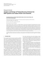
Let us briefly go through QoS attributes in UMTS. Maximum bit rate is
the maximum number of bits transmitted over a time interval. The traffic is
conformant with this parameter as long as it follows a token bucket algorithm,
where token rate is equal to maximum bit rate and bucket size is equal to maxi
-
mum SDU size parameter. The traffic is conformant with the guaranteed bit
rate as long as it follows a token bucket algorithm where token rate equals guar-
anteed bit rate and bucket size equals maximum SDU size. The general token
bucket algorithm is shown in Figure 2.6. Tokens represent the allowed data vol-
ume (e.g., in bytes for IP, or in packets for ATM). They are generated periodi-
cally according to the traffic contract and are stored in a token bucket (ATM
terminology), or we may say a token bucket counter (TBC) is increased by a fixed
value in each small time unit (IETF terminology). If the token bucket is full,
arriving tokens are discarded (TBC is equal to the bucket size). If TBC is bigger
than the incoming packet length, then the packet arrival is judged complaint
24 Traffic Analysis and Design of Wireless IP Networks
Table 2.2
UMTS QoS Attributes Defined for Each Traffic Class
Traffic Class Conversational Streaming Interactive Background
Maximum bit rate X X X X
Guaranteed bit rate X X
Delivery order X X X X
Maximum SDU size X X X X
Residual bit error ratio X X X X
SDU error ratio X X X X
Transfer delay X X
Traffic handling priority X
TEAMFLY
Team-Fly
®
(i.e., the traffic is conformant). Otherwise, the packet is marked as noncompli-
ant (i.e., the traffic is not conformant).
The delivery order specifies whether out-of-sequence packets are accept-
able or not to the destination. Maximum SDU size is defined for admission con-
trol and policing mechanisms (e.g., for policing the admitted bit rate). The
residual bit error ratio indicates the undetected bit error ratio, or if no detection
of errors is requested, it indicates the bit error ratio for the delivered SDUs. The
SER indicates the fraction of SDUs lost or detected as erroneous. It is used in
error detection schemes. Transfer delay indicates a maximum delay for the
ninety-fifth percentile of the distribution of delay for all delivered SDUs within
UMTS network. Traffic handling priority is defined to provide the possibility
for differentiation of the traffic within interactive traffic class (it is used for
scheduling purposes in the UMTS network nodes).
2.5.2.2 UMTS Architecture
UMTS architecture is described in [17, 18]. According to [17], UMTS’s basic
architectural split is between the user equipment (mobile terminals) and the
infrastructure. There are two trivial domains: the user equipment (UE) domain
and the infrastructure domain. UE is used users to access UMTS services. It
includes the identity module and mobile equipment, which may include several
functional software groups and hardware devices. The mobile equipment per
-
forms radio communication with the network and contains applications for the
services.
The infrastructure domain is further split in two domains: the network
access (NA) domain and the core network (CN) domain. The CN domain should
have capability to use any NA technique (at least, all global access techniques).
The NA domain consists of physical entities (nodes), which manage the radio
Third Generation Wireless Mobile Communications and Beyond 25
Tokens
Token
bucket
counter
Bucket
size
Packets
Server
Figure 2.6 Token bucket traffic shaper.
resources. The CN domain consists of physical entities, which provide support
for the features and telecommunication services (e.g., mobility management,
call management, and so forth).
The core network consists of the circuit-switched (CS) domain and packet-
switched (PS) domain, as defined by [17]. These two domains in CN are over
-
lapping in some common elements. CS mode is the GSM mode of operation,
while PS is the mode supported by the GPRS. The entities specific to CS
domain are MSC and GMSC. Of course, there are other entities used by the CS
domain, but they are shared with the PS domain. Specific entities for the PS
domain only are the GGSN and SGSN, which are introduced for the first time
in GPRS (i.e., 2G+). To distinguish between 2G and 3G entities we usually
write 3G-SGSN for SGSN in UMTS, while 2G-SGSN or just SGSN for
GPRS, and so on for other domain-specific entities, either for CS or PS domain.
The entities common to both domains in the core network, CS and PS, are
home subscriber server (HSS), AuC, VLR, EIR, and SMS-support nodes [17].
HSS is master database for a given user, which contains user identification
(numbering, addressing information), user security information (authentica-
tion, authorization), user location information, and user profile information (to
which services the user has access). In the previous releases of UMTS, instead of
HSS, the HLR was used. From now on, HLR for the CS and HLR for PS
domain are considered as subsets of HSS, where HSS additionally provides IP
multimedia functionality in the core network. Other common entities have
similar functions as previously described in the GSM and GPRS sections in this
chapter. The UMTS Network architecture is shown in Figure 2.7.
26 Traffic Analysis and Design of Wireless IP Networks
PSTN,
PLMN, ISDN
HLR
MSC/
VLR
GMSC
SGSN
GGSN
GGSN
Other data
network
Internet
Core network
PS domain
CS domain
External networks
RNC
RNC
Node B
Node B
Node B
Node B
UTRAN
Figure 2.7 UMTS network architecture.
Considering the access network, two different types are specified for
UMTS: the BSS and the radio network system (RNS). The BSS is the
GSM radio access network solution (also used for GPRS and EDGE).
BSS consists of the BSC and BTSs, where each BTS serves one cell. Usu
-
ally several BTSs are grouped in a base station and placed on a single site.
For UTRAN we need network elements responsible for radio resource
management, handover management, and power control. This network sys
-
tem, which corresponds to the GSM BSS, is the RNS, but it significantly dif
-
fers from the GSM access operation. RNS consists of the radio network
controller (RNC), which controls the radio access nodes, called Node B. A
Node B is a network component that serves one cell. We have different types
of Node B, such as macro, micro, and picocells, where we face different
requirements in traffic, coverage, and services. There are two types of Node B
for UMTS: Node B FDD and Node B TDD. The latter is targeted to hot
spots in coverage, while FDD is planned for wider coverage area (micro,
macro).
For lowering the costs of 3G system implementation, it is planned to colo-
cate BTS/Node B, and BSC/RNC sites. UMTS/GSM colocation ensures
greater efficiency by sharing space and infrastructure. An overall comparison of
2G, 2G+, and 3G mobile networks architectures, services, and terminal’s capa-
bilities is given in Table 2.3.
Third Generation Wireless Mobile Communications and Beyond 27
Table 2.3
Comparison of 2G and 3G Mobile Networks
Network
Second Generation
(2G)
Second Generation +
(2G+) Third Generation (3G)
Core network MSC/VLR, GMSC, HLR,
AuC, EIR
MSC/VLR, GMSC, SGSN,
GGSN, HLR, AuC, EIR
3G-MSC/VLR, 3G-GMSC,
3G-SGSN, 3G-GGSN, HLR,
AuC, EIR
Radio access
network
BSC, BTS, MS BSC, BTS, MS RNC, access node, mobile
station
Services Voice, SMS, ISDN
supplementary services
Voice, SMS, e-mail, WAP
services
Voice, Internet, multimedia
services, videotelephony
Data rates Up to 9,600 bps (or up to
14,400 bps)
Up to 57.6 Kbps for HSCSD;
Up to 115 Kbps for GPRS;
Up to 384 Kbps for EDGE
Up to 2 Mbps
Mobile
terminals
Voice-only terminals User-friendly terminals, en
-
hanced service capabilities
Voice, data, and video
terminals, multiple modes
2.5.2.3 UMTS Frequency Bands
In 1992, the World Administrative Radio Conference (WARC-92) identified
the 1,800 to 2,200-MHz frequency band for IMT-2000 [19]. 3GPP has speci
-
fied frequency bands for UMTS for both radio access modes, FDD and TDD.
In Europe 12 carrier pairs are available in FDD mode (5 MHz for uplink
and 5 MHz for downlink). So, in FDD, duplex connection is realized by using
different frequency carriers for uplink and downlink direction. In TDD mode,
uplink and downlink are implemented in the same frequency band (same car
-
rier). It is achieved by defining time frames and time slots. In TDD mode, the
network allocates radio resources on a time-slot basis in both uplink and down
-
link where time slots are grouped into frames. A certain number of time slots
within a time frame is allocated to uplink, and the remaining time slots to
downlink. So, the transmission occurs quasi-simultaneously. Seven 5-MHz car
-
riers are available in the TDD mode, as shown in Figure 2.8.
2.5.3 WCDMA
WCDMA is a UTRA-FDD mode of operation. It uses direct sequence CDMA.
The term wideband is used to differentiate WCDMA from 2G CDMA based on
technology pioneered by Qualcomm, called cdmaOne (or IS-95 CDMA).
WCDMA uses approximately three times wider bandwidth than cdmaOne (i.e.,
it uses bandwidth of approximately 5 MHz per carrier). The same carriers may
be reused in neighboring cells. Radio access network separates each user flow
(voice, data, and so forth) by multiplying the user information with pseudo-
random bits called chips. The chip rate specified for WCDMA is 3.84 Mcps
(millions of chips per second).
2.5.3.1 CDMA Operation
In CDMA operation the narrowband signal of the user is spread across the
whole bandwidth of the carrier, which is much wider. For this reason, CDMA
technology is sometimes referred to as spread spectrum. An example of the
spreading of the user signal is shown in Figure 2.9.
28 Traffic Analysis and Design of Wireless IP Networks
UMTS
TDD
UMTS FDD
uplink
UMTS
TDD
UMTS FDD
downlink
1,900 1,920 1,980 2,010 2,025 2,110 2,170
Fre
q
uenc
y
band (MHz)
Figure 2.8 Frequency bands for UMTS.
At the receiver end despreading of the wideband signal is needed. The
despreading process converts the wideband-spread signal back to the original
narrowband signal by multiplying the spread signal with the same pseudo-code.
This way the original narrowband signal is reconstructed, while other spread sig-
nals (from other users) are considered as noise, called interference. More user
traffic means more interference, which results in lower quality.
2.5.3.2 Why CDMA?
What is the advantage of CDMA over FDMA/TDMA techniques? In FDMA
and TDMA the common channel space is partitioned in orthogonal single-user
subchannels, which are not overlapping. In FDMA each user uses a certain fre-
quency band per call, which is not shared with other users during the call. In
TDMA the time is divided into time slots, and each user is given a time slot.
The problem arises when we have bursty traffic accessing the network (e.g., Web
traffic). In such cases we may need to transmit a larger volume of information
data in shorter time periods, and then silent period to follow, and so on. For
example, voice contains talk-spurts and silent periods. Also, a Web connection
contains active periods of browsing, and silent period for looking at (or hearing)
the information content. TDMA allows flexible rates in multiples of basic single
channels and subchannels (submultiples) for low bit rate transmitting. How
-
ever, it requires additional signal processing to cope with synchronization.
WCDMA supports rates up to 2 Mbps, utilizing variable spreading factor and
multicode links. User data is transmitted using 10-ms frames during which the
user data remains constant. By variable spreading factor, we address actual car
-
rier bandwidth, which may be between 4.4 and 5 MHz, by using grid of 200
kHz (e.g., it may be 4.4 MHz or 4.6 MHz). With the use of multicode links, we
address the assignment of additional codes when users demand more bandwidth
on the link (more codes gives more bandwidth). Spreading codes are designed to
allow the symbols from multiple users to occupy the same spectrum at the same
Third Generation Wireless Mobile Communications and Beyond 29
Frequency
Power
Frequency
Power
Users
1 and 2
Frequency
Power
User 2
Spreading Recovering
(a)
(b) (c)
User 1
User 2
User 1
Figure 2.9 Spreading the signal by CDMA: (a) unspread signal; (b) spread signal; and (c)
recovered signal.
time. WCDMA uses asynchronous transmission at the base station. For com
-
parison, IS-95 CDMA uses synchronous transmission where synchronization is
made possible by using Global Positioning System (GPS). Due to FDD mode,
WCDMA uses separate frequency bands to provide duplex connections.
2.5.3.3 Characteristics of WCDMA
Here we address some features that are specific to WCDMA, or to CDMA in
global terms. In CDMA, the individual connections between mobiles and base
stations are separated by the codes, while transmission takes place simultane
-
ously on the same frequency band. It is always possible to establish an additional
connection with the use of a new code. Hence, CDMA has soft capacity. How
-
ever, the more data being transmitted by the radio interface (in the cell or in
adjacent cells), the more noise disturbs the connection, thus reducing the quality
of the call. Because the available bandwidth per carrier is up to 5 MHz, data
transmission rates from 8 Kbps to 2 Mbps can be realized. Also, due to applica
-
tion of codes in CDMA, the same frequency bands can be used in the neighbor-
ing cells, resulting in frequency reuse factor of 1. This makes frequency planning
easier than in GSM. Furthermore, multipath propagation in WCDMA is con-
sidered as an advantage (it was the opposite case in GSM).
Soft Handover
User equipment and base stations use special RAKE receivers that allow each
UE to simultaneously communicate with multiple base stations. In WCDMA
we define two types of “soft” handovers: soft and softer handover. The former
refers to handover between the same carriers in cells belonging to neighboring
base stations, while the latter refers to soft handover between cells belonging to
the same base station. However, some hard handovers are still required in
CDMA networks. For example, for handover between FDD and TDD modes
in UMTS, only hard handover is possible.
Multipath Reception
The RAKE receivers also allow the UE to decode multiple signals that have trav
-
eled over different physical paths from the base station. For example, one signal
may travel directly from the base station to the UE, and another may reflect off a
large building or woods and then travel to the UE. This phenomenon, called
multipath propagation, also provides a diversity gain. The same effect occurs on
the uplink from the UE to the base station. WCDMA and cdma2000 have three
times bigger bandwidth than 2G CDMA (IS-95 standard), and hence have a
higher diversity gain.
Power Control
Transmissions by the UE must be carefully controlled so that all transmissions
are received with roughly the same power at the base station. If power control is
30 Traffic Analysis and Design of Wireless IP Networks
not used, a “near-far” problem occurs. In this case mobiles close to the base sta
-
tion overpower signals from mobiles farther away. The base station uses a fast
power control system to direct the mobile to power up or power down as its
received signal level varies due to changes in the propagation environment.
Similar, on the downlink, transmissions from the base stations are power-
controlled to minimize the overall interference throughout the system and to
ensure a good received signal by the UE. For example, in WCDMA fast power
control is applied with 1,500 Hz (for comparison, in GSM, power control has
an update frequency of only 2 Hz—that is, transmitting power level is changed
two times during one second).
Frequency Reuse of 1
Due to the application of codes in CDMA, the same frequency bands (carriers)
can be used in neighboring cells, so no frequency planning is required. But,
since every site causes interference to every other site, careful attention must be
paid to radio propagation for each site.
Soft Capacity
Capacity and coverage are intertwined in CDMA, depending on the number of
users in the system and the amount of interference allowed before access is
blocked for new users. By setting the allowed interference threshold lower, cov-
erage will improve at the expense of capacity. By setting the threshold higher,
capacity will increase at the expense of coverage. Because of the fundamental
link between coverage and capacity, cells with light traffic loads inherently share
some of their latent capacity with more highly loaded surrounding cells.
2.5.4 TD-CDMA
TD-CDMA is a solution for UTRA-TDD mode. It operates in time division
duplexing using the same frequency carrier for uplink and downlink (see
Figure 2.10). Uplink and downlink time slots are grouped into sequences. So,
the communication is quasi-duplex because at a given time slot, the mobile ter
-
minal only transmits data in the uplink, or receives data in the downlink. Here,
spreading codes separate user signals within one or more time slots. In
TD-CDMA we define a physical channel by a frequency carrier, a time slot, and
a code. For comparison, in FDD we use a carrier and a code to define a physical
channel. Each time slot can be assigned either to uplink or downlink, depending
on the demand. Users may occupy several time slots in a frame to obtain variable
transmission rates. Furthermore, we may achieve variable rates by varying the
spreading of a single code allocated to the given connection, or by adding more
codes (multicode) to the connection with fixed spreading.
Third Generation Wireless Mobile Communications and Beyond 31
2.5.5 cdma2000
The other of the ITU’s main candidates for 3G, besides UMTS, is cdma2000.
Considering the market, cdma2000 is oriented to the Americas and in part to
Asia. This standard is compatible with 2G CDMA IS-95 mobile systems, but it
is not compatible with 2G GSM. While WCDMA is asynchronous, cdma2000
is based on a synchronous architecture similar to IS-95 systems. The cdma2000
can be deployed in several phases [20]. The first phase, cdma2000 1x, supports
up to 384 Kbps packet data (theoretically) and doubles voice capacity of IS-95.
It operates in the 1.25-MHz channel. In the second release of 1x, two alterna
-
tives are currently proposed: 1xEV-DO (1x Evolution–Data Only) and
1xEV-DV (1x Evolution–Data and Voice). The 1xEV-DO provides pure data
over the network (i.e., a carrier will be reserved for data only). This way it is pos
-
sible to achieve data rates above 2 Mbps. A disadvantage of such approach is
inefficient frequency space utilization. For example, if the network is loaded
with “heavy” voice traffic and low data traffic, the free resources from the data-
only carrier cannot be allocated to voice traffic. In 1xEV-DV, cdma2000
provides more flexibility by mixing data and voice traffic on the same carrier.
The second phase of cdma2000 is called 3x, which introduces higher data rates
at the expense of cell coverage. The chip rate of cdma2000 3x is 3.6864 Mcps,
which is slightly lower than in WCDMA. But the chip rate is three times the
chip rate in an IS-95 system that provides compatibility between the systems
and easy migration from IS-95 to cdma2000. Also, there is a potential CDMA
Nx(N > 3) ought to support much higher data rates than 2 Mbps.
In the next section we refer to the Wireless IP standard defined for
cdma2000, as well as its QoS concept.
32 Traffic Analysis and Design of Wireless IP Networks
Fre
q
uenc
y
Time
UL
UL
DL
DL
UL=Uplink
DL=Downlink
Frame with
time slots
n
Code
Figure 2.10 UTRA-TDD mode (TD-CDMA).
2.5.5.1 Wireless IP Standard for cdma2000
Within cdma2000 is defined a standard called “Wireless IP standard” [21],
which defines requirements for the support of wireless packet data networks in
cdma2000. Its reference model is given in Figure 2.11. This standard defines
two methods for accessing packet data networks:
•
Simple IP;
•
Mobile IP.
The main tendency in Wireless IP standard is usage of already existing
IETF protocols for mobility support. In Simple IP the user is assigned a
dynamic IP address from the Public Data Service Network (PDSN). The user
retains its IP address as long as it is in the service area (radio network) of the
assigning PDSN. Simple IP does not provide IP mobility beyond the PDSN.
Mobile IP is defined in RFC 2002 [9]. We refer to it in more detail in the next
chapter. The mobile station is assigned either a nonzero static IP address or a
dynamically assigned IP address belonging to its home IP network, called the
Third Generation Wireless Mobile Communications and Beyond 33
HLR
Home access
provider
network
RADIUS
Home
IP network
Broker
network
HA
Mobile IP
network
Simple IP network
Internet
PDSN
Radio network
Signaling network
Visited access
provider network
PDSN - Packet data serving node
RADIUS - Remote authentication dial-in user service
HA - Home agent
VLR
RADIUS
RADIUS
Figure 2.11 Reference model for access in the Wireless IP network.
home address (HA). In this case the user is able to have a persistent IP address,
even at handover between separate PDSNs.
Both Simple IP and Mobile IP utilize Remote Authentication Dial-In User
Service (RADIUS) servers, which use the RADIUS Protocol for carrying authen
-
tication, authorization, and configuration information between a network
access server that desires to authenticate its links and a shared authentication
server [22]. RADIUS is built over the UDP/IP protocol stack. There are three
types of RADIUS servers: home, visited, and broker RADIUS. Home RADIUS
resides in a Home IP network, and visited RADIUS resides in Visited IP net
-
work. Broker RADIUS is an intermediate optional server (or servers) that has
security relations with the visited RADIUS and the home RADIUS, and is used
to transfer messages between the Visited IP network and Home IP network.
Considering the mobility management (i.e., support for continuality of
the connection during the radio interface change), and by using Figure 2.12, the
standard defines two types of handovers (or handoffs):
1. Packet call function (PCF)-to-PCF handover (refer to Figure 2.12),
where a Point-to-Point Protocol (PPP) session continues if the handover
occurs between access points in the same PDSN; if the handover is to
different PDSNs, a new PPP session needs to be established.
2. PDSN-to-PDSN handover, which requires Mobile IP. This type of
handover needs detection of the FA and establishment of new PPP
session after successful authentication in the target PDSN.
In 3GPP2 proposals for Wireless IP, QoS is limited to support for differ-
entiated services (we refer to them in next chapter). Mobile stations are allowed
34 Traffic Analysis and Design of Wireless IP Networks
Home agent
PDSN PDSN
PCF PCF PCF
BSC BSC BSC BSC
BTS BTS BTS BTS BTS BTS
Radio access network
IP core network
Figure 2.12 Packet data mobility concept in cdma2000.
TEAMFLY
Team-Fly
®
to mark IP packets with a differentiated services (DS) class, which they transmit
to network. However, PDSN may accept this mark or it may remark the packet
based on user profile’s DS class options at the home server.
2.5.5.2 QoS in cdma2000 Systems
QoS is defined from the perspective of the users and/or the system operator [23].
From the user perspective, cdma2000 defines different QoS service levels, where
each level has an associated profile for the QoS requirements of that service. All
applications are classified into QoS groups. Here, QoS refers to the ability of a
network operator to support the end user requirement with regards to four QoS
parameters:
1. Bandwidth;
2. Latency (delay);
3. Jitter (delay variation);
4. Traffic loss.
Network QoS consists of two parts:
1. The first part consists of a mechanism for negotiation of the QoS serv-
ice level between applications on the user’s end and application servers,
for some or for all data traffic carried between them through the net-
work. The aim of such a mechanism is to ensure constraint on the user
QoS parameters (i.e., bandwidth, latency, jitter, and loss), with a speci-
fied probability, which is not negotiated.
2. The second part consists of set of protocols between network ele
-
ments, which are used to negotiate QoS characteristics on each link
(e.g., a hop) or path through a single network carrier.
Similar to the UMTS QoS concept, cdma2000 supports four traffic
classes: conversational class, streaming class, interactive class, and background
class. Attributes of traffic for defined classes are identical to those of UMTS.
We may conclude that UMTS and cdma2000 are converging towards a
unified QoS concept (i.e., both standards have the same traffic classification
considering the QoS).
2.6 Third Generation Mobile Applications and Services
So far, we conclude that there are two main concepts for 3G mobile systems:
UMTS standardized by 3GPP, and cdma2000 standardized by 3GPP2. In both
concepts the mainstream is towards:
Third Generation Wireless Mobile Communications and Beyond 35
1. Packet-based radio-access (with IP technology) for the purpose of sta
-
tistical multiplexing and integration of heterogeneous services over the
wireless access network and core network of the mobile operators;
2. Introduction of new services and content, which increases the revenue
from the users.
According to the 3GPP proposal [24], a network offers three types of
services:
1. Bearer services;
2. Teleservices;
3. Supplementary services.
Bearer services involve only low layer functions, in reference to the OSI
model. In 3G they should support both domains, CS and PS. Bearer services for
UMTS may be connection-oriented or connectionless services. They are
required to provide guaranteed (constant) bit rate and real-time dynamically
varying bit rate. Real-time and nonreal-time services should be supported. This
implies that bearer services should have the ability to provide guaranteed real-
time service with guarantees on bit rate, delay, and delay variations. Because
nonreal-time services will be on the same link as real-time services (at least in
UMTS), bearer services should provide the ability for QoS differentiation
between different users. Also, multimedia applications should be supported. By
definition [24], multimedia refers to several user flows to/from the user having
different traffic types, such as real time and nonreal time.
Applications that are on higher layers according to the OSI model should
specify their traffic requirements to the network by requesting appropriate
bearer service. Considering the entities included in communication, bearer serv
-
ices may be:
•
Point-to-point, which can be unidirectional or bidirectional. In the lat
-
ter case we may further divide the services into symmetric or
asymmetric;
•
Point-to-multipoint, which may be multicast (in this case receiving ends
are specified) or broadcast (receiving end points are not explicitly speci
-
fied by the sender, but any receiver should have ability to admit or
reject such service).
We previously introduced four QoS classes, which refer to bearer services.
According to requested bearer service, each application may be classified into
one of the QoS (traffic) classes. In UMTS, an application requests bearer service
36 Traffic Analysis and Design of Wireless IP Networks
by specifying any of the following: traffic type, traffic characteristics (e.g.,
point-to-point), maximum transfer delay, delay variation, bit error ratio, and
data rates. Each mobile terminal may have several bearer services simultaneously
(each of which may be connection-oriented or connectionless). In such a case,
we may refer to the cumulative bit rate of the mobile terminal. In [24], maxi
-
mum cumulative bit rates for UMTS are specified, which are:
•
Up to 144 Kbps for rural environment or for satellite radio access;
•
Up to 384 Kbps for urban/suburban outdoor environments;
•
At least 2 Mbps for indoor radio environment.
However, radio and network interfaces have granularity limitation consid
-
ering the supported bit rates. To allow for the support of flexible bandwidth
on-demand services, bearer services should be provided with the finest possible
granularity that can be efficiently supported. The aim is to increase bandwidth
usage efficiency through the means of statistical multiplexing.
By definition [24], teleservices provide full capability of communication
by using terminal equipment, network equipment, and some dedicated centers
to that service. The teleservice and its meaning is also defined by ITU-T Recom-
mendation F.700 [25]. Teleservices may be grouped into single media services
(e.g., speech) and multimedia services. There are six specified categories of mul-
timedia services:
1. Multimedia conference services;
2. Multimedia conversational services;
3. Multimedia distribution services;
4. Multimedia retrieval services;
5. Multimedia messaging services;
6. Multimedia collection services.
Teleservices require association of terminal and network capabilities. Here,
upper layer capabilities (in reference to the OSI model) are necessary. However,
lower layer capabilities are always needed (i.e., there is mapping between each
teleservice and some of the bearer services in the system). Teleservices supported
in 2G mobile systems are:
•
Speech (telephony);
•
Emergency call;
•
SMS.
Third Generation Wireless Mobile Communications and Beyond 37
Speech is a service that should be supported by any mobile system. Emer
-
gency call has a speech component, but it has significantly reduced authentica
-
tion requirements compared to telephony (usually, it is always allowed for a user
to make an emergency call). SMS may be point-to-point (SMS-PP) or cell
broadcast (SMS-CB). Additionally, UTRAN shall provide interworking with
external data networks, of which the Internet is seen as the most important one.
Therefore, Internet access is considered by 3GPP as one of the main teleservices.
The most important benefits from the definition of Internet access are: opti
-
mized transmission of IP traffic over the radio interface considering the scarce
radio resources, and implementation of QoS mechanisms. QoS mechanisms
should be compliant with those defined for the Internet. A typical QoS mecha
-
nism, foreseen as a main candidate for 3G and beyond, is differentiated services
(which is described in Chapter 3).
The third generic type of services is supplementary services. A supplemen
-
tary service supplements a basic telecommunication service (i.e., teleservice).
Such services are offered in 2G mobile systems, such as GSM, and they continue
to be offered in 2G+ and 3G systems. Examples of supplementary services
include the following: calling/connected line identification presentation/restric-
tion, call forwarding (on subscriber busy, no reply, not reachable, or uncondi-
tional), call waiting, call hold, multiparty service, closed user group, advice of
charge, and barring outgoing/incoming/roaming calls.
2.6.1 New Killer Applications
The answer cannot be easily given to the question: What will be or what are the
killer applications for 3G and beyond over the next several years? Additionally,
one may ask whether such applications would be spread worldwide, or be locally
based.
Because users choose applications that are of value to them considering
some merit (e.g., a need, a personal image, popularity), it should be noted that
applications are not always driven by the technical merit (e.g., bandwidth). So,
it is not simply a question of mobilizing the content found on Internet, but it is
a question of creating applications that capture the needs of the users in terms of
mobility. Some analysis leads to the conclusion that, in the future, revenue from
voice services will slowly decline due to regulation, saturation of the user market,
new services, as well as competition among the operators over a same geographic
area. On the other hand, one may expect broadband packet-based data services
to be offered to the users.
Key services in future mobile systems are in the areas of multimedia mes
-
saging, m-commerce, and location-based services. Of course, voice will continue
to be the dominant service in the next several years. Predictions show that by
38 Traffic Analysis and Design of Wireless IP Networks
2010, revenue from voice will decline below one-half of the total revenue from
mobile networks.
The deployment of 3G mobile networks should provide a set of broad
-
band services at different data rates using CDMA-based techniques. However,
the radio interface’s bandwidth can be further extended by wireless LAN tech
-
nologies, such as IEEE 802.11, High Performance Radio LAN (HIPERLAN) 1
and 2, as well as Bluetooth and satellite networks. The bit rate provided to the
user in next generation mobile networks depends on several factors. One of
them is the velocity of the user, which is inversely proportional to the bit rate
that can be allocated to the user by the network.
There are standardization efforts for the creation of protocols that will
support bearer transparency at the application layer. Examples of such protocols
are the Wireless Application Protocol (WAP) and Freedom of Multimedia Access
(FOMA). The latter is created for support of services offered by NTT DoCoMo
in Japan. The WAP standard [26] is introduced for 2G+ mobile networks; 3G
networks should also support it. However, WAP needs the so-called WAP-
gateway network node (for conversation between HTTP and WAP), and there-
fore it is an optional protocol for the mobile network. The trend is to integrate
WAP with current Internet standards that are proposed by IETF. The target is
to create optimized HTTP/TCP protocol stack that will allow presentation of
Web content to any browser on any device, from PCs and laptops to mobile ter-
minal and PDAs.
One of the starters in 3G is NTT DoCoMo from Japan [27]. They have
created the very successful i-mode mobile Internet service, which provides easy
e-mail and Internet access using the existing HTTP protocol (created for wired
Internet). FOMA is an advanced version of i-mode. It provides multimedia
messaging such as e-mail with attached sound file and still images, downloading
JPEG pictures, downloading and playing network games (based on Java tech
-
nology), and support for video images via i-mode. FOMA can be used as a
packet-switched service (data rates up to 384 Kbps in downlink), but it can also
be used in circuit-switched mode (64 Kbps in each direction, uplink and down
-
link). So, we may classify killer applications in 3G in several groups:
•
Personal services, such as gaming (playing games by using a mobile ter
-
minal and a mobile network), multimedia messaging services (messages
with attached audio, video files, and/or still images), location-based
services (e.g., city guide, local information services, GPS mapping
information), mobile instant messaging (e.g., “chat”), on-line shopping
(viewing and purchasing merchandise via mobile), and many others.
•
Business services, such as videoconferencing (video and audio conference
over distance), mobile commerce (receiving/sending customer and sales
data), and on-line stock trading via the mobile.
Third Generation Wireless Mobile Communications and Beyond 39
•
Home services, such as mobile office (intranet access from mobile termi
-
nal, database access), home surveillance (i.e., distance control of the
home security system), distance control of home appliances (e.g., one
may choose to start the heating system while driving home on the high
-
way).
•
Entertainment services, which include information and audio or video
clips from sport events, theaters, concerts, as well as previews of cin
-
ema/TV movies. Here, we must mention audio and video streaming as
an option. However, streaming services also refer to viewing/listening
to shorter clips rather than watching movies or TV via the mobile,
which are not considered to be killer applications due to high band
-
width requirements (especially for video streaming) in time-continuous
flows during longer time periods (such service will be too costly to be
attractive to the users).
However, these new services require mobile terminals with certain capa-
bilities. The mobile terminal has a significant effect on the usage of services (easy
to use, quality of reproduction, support for multiple services and operation
modes). Dual-mode and multimode terminals are needed for the transition
between 2G and 3G, and such will be needed for the transition between 3G and
next generation mobile networks (e.g., 4G). Terminals should support simulta-
neous voice and data capability (e.g., voice conversation and downloading a file
at the same time).
An important issue is the charging (billing) of these killer applications.
While in voice service, billing is based on the duration of the call, GPRS allows
charging based on transmitted information volume (for data services). However,
sometimes it is not convenient to charge per megabyte downloaded. The user
will rarely download a song if it is cheaper to purchase a CD in a store. On the
other hand, tracking real-time events while on move (e.g., downloading a video
clip immediately after a scored goal in a football game) or previewing a clip from
cinema movie is a different situation, where the user will pay for recent news,
interesting information, or entertainment. However, many operators are mov
-
ing from a traditional time-based billing approach to a model of billing that sets
a fee for a certain service over a longer period (e.g., a week or a month), while
giving users freedom to use that service as much as they want or within certain
limits (in number of events, in time usage, or in data volume). Of course, differ
-
ent tariff models and different associated QoS classes should be used to optimize
the utilization of the network resources.
Finally, another issue that is important is security. For example, mobile
terminals with Web browsing capabilities may experience a new wave of viruses
and hackers. There is no 100% protection, but certain security mechanisms
40 Traffic Analysis and Design of Wireless IP Networks
should be applied. Traditional approaches include authentication (using unique
user number), authorization (checking for admitted services to the user), and
encryption of transmitted data (protecting data on the link by applying some
type of encryption of data bits). In contrast to 2G networks, in this case (with
many new services), security and trust is not addressed to network opera
-
tors/providers only, but also to service providers, which shall provide services by
using the network resources. However, a network operator may also be a service
provider.
2.6.2 Real-Time Services
First, let us define a real-time service. Real-time refers to services that use one-
way or two-way transmission of information where:
•
The time relation between information entities shall be preserved (i.e.,
different media streams should be synchronized);
•
Conversational services have very stringent requirements on delay.
Both requirements should be satisfied for real-time conversational services,
while only the first one is required for real-time streaming services.
2.6.2.1 Real-Time Conversational Services
The most well known and the oldest of real-time services is telephony speech. In
GSM it is basic service (it is based on circuit-switching). In packet-switched net-
works, such as 3G mobile networks and beyond, new applications require this
scheme, such as IP telephony, videophone, and videoconferencing tools.
IP telephony has similar QoS requirements as CS telephony (e.g., GSM).
The human ear is highly intolerant to delay variation (it should be less than
1 ms). Also, it has stringent tolerance on delay (delay 30 ms: the user does not
notice any delay; delay 100 ms: the user does not notice it when echo cancellers
are applied in the network). ITU-T has specified in Recommendation G.114
that the preferred delay for one-way voice communication is in the range 0 to
150 ms, while up to 400 ms is also acceptable. Above 400 ms, it is not. On the
other hand, experimental studies suggested that frame error ratio (FER) less than
3% is acceptable for telephony.
Videoconferencing services provide two-way transmission of real-time
video, audio, and other media. Latency (delay) is the key parameter for these
services. In the case of a multimedia conference, an important issue is synchro
-
nization between different media streams (e.g., video and audio). Also, it is not
feasible to recover retransmission errors or losses by retransmission mecha
-
nism because of added delays. However, the use of error-recovery and error-
Third Generation Wireless Mobile Communications and Beyond 41
concealment techniques are necessary to ensure graceful performance degrada
-
tion over the wireless link, which has time-variable error ratio. According
to [28], videoconferencing services are symmetric and include encoding, trans
-
mission, interpreting, and decoding components. Such services are allowed in
PS mode and CS mode. Videoconference service should coexist with other data
service options on the same wireless link. However, QoS requirements may be
applied only to the portion of the communication link within the wireless net
-
work. The videoconferencing service shall be compatible with ITU-T standards
for video conferencing, such as H.324M/H.323 and its adaptation to circuit-
switched multimedia telephony service [29]. Data rates for videoconference
may range from 32 Kbps up to 384 Kbps in 3G standardization groups, both
3GPP (with UMTS) [24] and 3GPP2 (with cdma2000) [28]. Videophone
shall apply the same delay requirements as for conversational voice. However,
audio and video must be synchronized within certain limits to provide “lip-
synch” (synchronization of speaker’s lips with the speech at the receiving end).
So, lip-synch 100 ms is specified for UMTS, while it shall be below 20 ms
(inter media skew) for cdma2000.
Other real-time services are interactive games (i.e., on-line gaming), two-
way telemetry, and telnet [24]. Game requirements is dependent on the type of
game (e.g., a slow game like chess versus a fast game such as racing), but in all
cases delay should be kept below 250 ms. Two-way telemetry and telnet have
similar delay requirements as on-line gaming.
2.6.2.2 Real-Time Streaming Services
In this section we classify audio streaming, video streaming, and multimedia
streaming services. These services shall be allowed for the first time in the wire
-
less environment in 3G mobile networks. Streaming refers mainly to unidirec
-
tional stream with high continuous utilization of bandwidth.
Audio streaming is intended to provide better quality than conversational
telephony service (it includes music, surround noise). Because there is no con
-
versational element involved, audio streaming is allowed to have higher delay,
but this is limited because of the limited buffer capacity at the receiving mobile
terminal.
Video streaming (one-way video) has similar performance requirements
as audio streaming. It includes audio and video streams. Video streaming
enables users to view videos within certain playout delay, instead of download
-
ing the whole video file before it can be viewed. Thus, this service allows the user
to start viewing video soon after downloading begins. Considering the delay,
the maximum playout delay recommended by [28] is 30 seconds, while the
maximum delay for this service specified in [24] is 10 seconds. In both standards
it is specified that FER ≤ 1%. For circuit-switched systems it corresponds to a
BER ≤ 0.1%.
42 Traffic Analysis and Design of Wireless IP Networks
Multimedia streaming includes streaming of audio, video, and multimedia
data. It is defined as separate service by 3GPP2 [30]. This service is generally
used in multimedia and message retrieval, video-on-demand, pay-TV, interac
-
tive news retrieval, and other multimedia broadcasting. It requires similar per
-
formances as video streaming. On the other side, multimedia streaming includes
content creation and transmission. The receiving side decodes the data by send
-
ing packets from each media stream to corresponding audio/video codec and by
performing synchronization between streams and content reproduction.
Also, we may provide multimedia services by using the push service, which
delivers information initiated from a network (which may be external to the
mobile network) to the mobile terminal. This service will cause a PDP context
(refer to Section 2.4.2) to be activated if needed. Consumers should be able to
choose to accept/reject push services through pop-up menus that should make
navigation of services more efficient. Push services should allow customers to
continuously refine their customer profiles.
All streaming services usually include control protocols for setting up con-
nection between parties and negotiating various options for the particular
service.
2.6.3 Nonreal-Time Services
In nonreal-time services we classify all 3G interactive services and background
services.
Typical interactive services are voice messaging, Web browsing, high-
priority transactions (e-commerce), and e-mail retrieval (server access). For
interactive services round-trip delay is one of the most important parameters
because the receiving-end peer expects the requested information within a rea
-
sonable time period. Experimental studies have shown that for these services
acceptable delays are in the range 2 to 4 seconds. However, lower delays are
always desirable (e.g., delay of 0.5 second is desirable for Web browsing).
Another group of nonreal-time services are background services. Typical
examples are delivery of e-mail (server to server), SMS, fax, and low-priority
transactions. These services have no specified requirements on delay or delay
variation. However, the information should be delivered to the user within a
reasonable time, which ranges from tens of seconds to several hours. Reasonable
time for SMS and fax is up to 30 seconds, while for e-mail is up to several hours
(also, it is dependent on the end user). The only strict requirement is that infor
-
mation should be delivered to the user error-free. For that purpose, a mecha
-
nism for retransmissions of lost or corrupted packet is usually applied
(e.g., TCP). Table 2.4 gives an overview of 3G services considering the QoS
class and performance requirements.
Third Generation Wireless Mobile Communications and Beyond 43
2.7 Future Wireless Communication Networks Beyond 3G
There is continuous evolution of mobile networks. The 2G introduced digital
wireless access and many supplementary services based on ISDN technology.
The 2G+ networks, such as GPRS, used a combination of CS and PS modes in
the core network. The 3G networks have IP-based radio access networks (RANs),
and the so-called 3G-core network, which has CS and PS capabilities. The next
generation mobile networks are going towards all-IP networks, including an
all-IP core network and IP RAN. The first move towards all-IP networks is made
in 3G by the definition of the IP Multimedia (IM) core network [31]. The evolu
-
tion of mobile networks towards an all-IP network is shown in Figure 2.13.
The next generation wireless networks are supposed to continue the evolu
-
tion of the mobile world beyond 3G. There is a lot of ongoing work considering
the next generation (e.g., 4G). In this section we will refer to it as FutureG
(future generation mobile networks). If we follow the evolution path of mobile
networks until 3G, we may extract two main drivers:
•
Higher data rates;
•
New multimedia services.
44 Traffic Analysis and Design of Wireless IP Networks
Table 2.4
Performance Comparisons of Main 3G Services
Service Traffic Class
Real
Time
Data Rate
(Kbps)
Loss
(FER) Delay Jitter
Voice Conversational Yes 4–25 <3% <150 ms <1 ms
Videophone Conversational Yes 32–384 <1% <150 ms N/A
Gaming Conversational Yes <32 0 <250 ms N/A
Two-way telemetry Conversational Yes <32 0 <250 ms N/A
Voice messaging Interactive No 4–13 <3% <2 seconds <1 ms
WWW Interactive No 0 <4 seconds N/A
E-commerce Interactive No 0 <4 seconds N/A
E-mail access Interactive No 0 <4 seconds N/A
Audio streaming Streaming Yes 32–128 <1% <10 seconds N/A
Video streaming Streaming Yes 32–384 <1% <10 seconds N/A
SMS Background No 0 <30 seconds N/A
Fax Background No 0 <30 seconds N/A
E-mail (between
servers)
Background No 0 Variable N/A
TEAMFLY
Team-Fly
®
Using this approach, FutureG shall provide more bandwidth (beyond 2
Mbps) and find new frequency bands for a new standard [32]. The path to
FutureG is not so straightforward, however. One of the main concerns in
FutureG is that it will be deployed in a situation when there will be variety of
wireless and wired communication networks (e.g., 3G, GSM, wireless LAN,
Bluetooth, or xDSL for wired access). According to the current expectations of
the vendors and researchers in the wireless community, FutureG will be more
focused on services and user needs by using wireless infrastructure in a more
transparent way. Using the standards, a few large global companies, vendors,
and organizations control the wireless market. It is expected that interface stan
-
dards and frequency bands will become of secondary concern, although they are
needed and should be specified.
If mobile networks have evolved from a 10-Kbps data rate in 2G (e.g.,
9.6 Kbps in GSM) to 2 Mbps in 3G (which is almost a 200 times higher data
rate than in GSM), then we may expect data rates in FutureG radio interface of
100 Mbps or more [32]. An example of an application that may need such a
high data rate is telepresence, which is a foreseen application that will be used to
create virtual meetings between individuals, and provide full simulation of all
senses required to provide an illusion of actually being somewhere else. In that
sense, mobile terminals will become extremely computational capable.
A mobile terminal in FutureG will not only present information to the
user, but it should also be capable of gathering information about the user or the
environment (e.g., by using a camera or some sensor placed on the front of the
Third Generation Wireless Mobile Communications and Beyond 45
BSC
Internet
BTS
BTS
GSM/GPRS
core network
3G core
network
RNC
Node B
Node B
2G(+)
3G
FutureG
All-IP core
network
RAN
RAN
IP connectivity
BSS
Figure 2.13 Evolution towards an all-IP mobile network.
mobile, generating content by using a specific application in the mobile termi
-
nal). So, the user would be a service provider in some cases. For example, a user
may leave a message about a car crash on the highway with which it will inform
other drivers to avoid that road. Furthermore, in FutureG the user should not
rely on a single type of access network, or on a single operator. Even if there is
no presence of an operator’s network, the user should be able to use ad hoc
applications to communicate with other users in the area of coverage of the
mobile terminal.
The discussion on FutureG leads to the following possible key drivers (or
demands) for the evolution of mobile networks beyond 3G:
•
Open mobile service architecture;
•
Adaptive personal mobility;
•
Device mobility;
•
Direct access to Internet.
We briefly describe each of the FutureG drivers given above in the follow-
ing section.
Open Mobile Service Architecture
FutureG should have an open service architecture that will allow deployment of
new services by service providers or by users anytime and at anyplace [33]. Also,
different wireless access networks in FutureG should support service mobil-
ity—that is, allowing the user to use same services independently of the type of
wireless access network (e.g., a user should be able to make a voice call in a wire
-
less LAN in the same manner as in a GSM network).
Adaptive Personal Mobility
The user should have the possibility to move to other wireless networks and at
the same time remain reachable using the same address (e.g., IPv6 address). For
support of adaptive personal mobility, FutureG will incorporate personal agents
(virtual software objects) that will reside in the Internet and should provide
access and media control for the user considering the network condition (e.g.,
signal strength from the network, current network capacity, QoS demands) and
user equipment (e.g., installed software in mobile terminal and its capabilities).
Device Mobility
Mobile terminals in FutureG are expected to become more complex because
they should support different radio interfaces. Furthermore, they should have
multiple sensors for gathering information from the user and environment, and
they should have capabilities for presentation as well as for creation of
46 Traffic Analysis and Design of Wireless IP Networks
multimedia contents. Thus, FutureG will incorporate multinetwork and multi
-
function terminals. Of course, cheap single-service terminals will remain on the
market, targeting different user profiles.
Direct Access to the Internet
FutureG should also incorporate direct access to Internet. This will be necessary
because broadband Internet access is being provided in a rapidly increasing way,
and not only by telecommunication operators and vendors (in many cases it is
provided by transportation companies and power companies). Wireless LAN
and/or wireless broadband access network (BAN) are considered part of the
FutureG. Furthermore, there are existing solutions for direct access to the Inter
-
net (without any subscription, authorization, or authentication to the network
operator), such as e-cash. In this case operators provide IP access, while billing of
the used services is transferred to a third party (it should be a trusted party). This
way, network operators as well as service providers may be paid directly or indi
-
rectly. In such a situation, users can use any service from any third party without
any intervention by the network operator, which in such cases only provides
access to the network.
Finally, we may define the FutureG mobile networks (e.g., 4G) consider-
ing their foreseen characteristics as described above.
Definition of FutureG Mobile Networks.
FutureG (beyond 3G mobile network)
will be an end-to-end wireless IP network with high bandwidth gathered by ex-
ploiting heterogeneous wireless access, and with the capability for direct IP con-
nectivity to different multimedia services provided by a third party. The concept
of FutureG is information anywhere, anytime, and in any form.
2.7.1 All-IP Mobile Network
The main drivers for an all-IP network are resource efficiency (by means of sta
-
tistical multiplexing), operational costs, and the transparency of IP technology
to different types of services. Therefore, telephony will also migrate from CS to
PS (i.e., IP telephony). However, the inertia from 2G and the first 3G mobile
systems will be an intrinsic element in this area during the first decade of the
twenty-first century.
Internet services are made closer to the mobile terminal by the introduc
-
tion of the GPRS system and WAP. The market will change with the emergence
of new killer applications, which is happening now. Mobile Internet is the busi
-
ness model for the future of cellular technology. IP mobility will give the opera
-
tors unlimited possibilities for service differentiation. Such an approach allows
unlimited possibilities for the introduction of new services and the creation of
new content, as shown in Figure 2.14.
Third Generation Wireless Mobile Communications and Beyond 47