windows server 2008 tcp ip protocols and services microsoft 2008 phần 4 pps
Bạn đang xem bản rút gọn của tài liệu. Xem và tải ngay bản đầy đủ của tài liệu tại đây (1.14 MB, 51 trang )
Chapter 5: Internet Protocol (IP) 121
Internet Timestamp
The Internet Timestamp option is used to record the time that an IP datagram arrived at each
IP router in the path between the source and destination host. The Internet Timestamp option
is similar to the Record Route option in that the sending node creates blank entries in the IP
header that routers fill out as the packet travels through the IP internetwork. Each entry con-
sists of the router’s IP address and a 32-bit integer timestamp that indicates the number of mil-
liseconds since midnight, Universal Time. If Universal Time is not being used, the high-order
bit of the timestamp field is set to 1.
Note
To use Internet timestamps, Internet timestamping must be enabled on all the routers
in the path between the source and destination hosts. It is common for routers to either not
support Internet timestamping or have it disabled.
The Internet Timestamp option contains the following fields:
■ Option Code Set to 68 (Copy Bit=0, Option Class=2, Option Number=4).
■ Option Length Set by the sending host to the number of bytes in the Internet Times-
tamp option.
■ Next Slot Pointer Set to the byte offset (starting at 1) within the Internet Timestamp
option of the next slot for the recording of the IP address and timestamp. The Next Slot
Pointer field’s minimum value is 5.
■ Overflow Set by routers to indicate the number of routers that were unable to record
their IP address and timestamp.
■ Flags Set by the sending host to indicate the format of the IP Address/Timestamp slots.
When Flags is set to 0, the IP address is omitted. This allows up to nine timestamps to
be recorded. When Flags is set to 1, the IP address is recorded, allowing up to four IP
address/timestamp pairs to be recorded. The Internet Timestamp option format shown
assumes Flags is set to 1. When Flags is set to 3, the sending node specifies the IP
Option Code
Option Length
Next Slot Pointer
Overflow
Flags
First IP Address
First Timestamp
=68
122 Part I: Internet Layer Protocols
addresses of successive routers: A timestamp is recorded only if the IP address in the slot
matches the router’s IP address.
■ First IP Address/First Timestamp Set by routers to record the IP address and timestamp
of the routers encountered (when Flags is set to 1) or specified (when Flags is set to 3).
When a sending host sends an IP datagram with the Internet Timestamp option, the sending
host does the following:
1. Sets the Next Slot Pointer field’s value to 5.
2. For a specified route (when Flags is set to 3), places the series of IP addresses in the
Internet Timestamp option.
When an IP router receives an IP datagram with the Internet Timestamp option, it compares
the Option Length and Next Slot Pointer fields. If the Next Slot Pointer field’s value is less
than the Option Length field’s value, it does the following:
■ If Flags is set to 3, the router replaces the IP header’s destination IP address with the IP
address that is recorded in the next slot (based on the Next Slot Pointer field).
■ If Flags is set to 1 or 3, the router records the IP address of the interface on which the IP
datagram was received in the same slot.
■ If Flags is set to 0, the router records the timestamp and adds 4 to the Next Slot Pointer
field. If Flags is set to 1, the router records the timestamp after the IP address and adds
8 to the Next Slot Pointer field. If Flags is set to 3, the router replaces the IP address and
adds 4 to the Next Slot Pointer field.
If the Next Slot Pointer field’s value is greater than the Option Length field’s value, the router
increments the Overflow field. If the Overflow field is 15 before incrementing, an ICMP
Parameter Problem is sent back to the source host.
Setting the Internet Timestamp Option with Ping
The Windows Server 2008 and Windows Vista Ping.exe tool and the -s option can be used to
send ICMP Echo messages with the Internet timestamp. The syntax is the following:
ping -s
Slots Destination
For example, to ping the IP address of 10.9.1.1 using Internet timestamps with three slots, use
the following command:
ping -s 3 10.9.1.1
Network Monitor Capture 05-06 (in the \Captures folder on the companion CD-ROM)
provides an example of Ping.exe tool traffic and the use of the Internet Timestamp option.
Chapter 5: Internet Protocol (IP) 123
Summary
IP provides the internetworking building block for all other Internet Layer and higher proto-
cols in the TCP/IP suite. IP provides a best effort, unreliable, connectionless datagram delivery
service between networks of an IP internetwork. The IP header provides addressing, type of
delivery, maximum link count, fragmentation, and checksum services. IP fragmentation pro-
vides a way for IP datagrams to travel over links with a lower IP MTU than the original IP dat-
agram. The basic services of the IP header are extended through IP options, the most common
of which provide source routing, path recording, router alert, and timestamping functions.
125
Chapter 6
Internet Control Message
Protocol (ICMP)
In this chapter:
ICMP Message Structure. . . . . . . . . . . . . . . . . . . . . . . . . . . . . . . . . . . . . . . . . . . . . . . 126
ICMP Messages . . . . . . . . . . . . . . . . . . . . . . . . . . . . . . . . . . . . . . . . . . . . . . . . . . . . . . 127
Ping.exe Tool . . . . . . . . . . . . . . . . . . . . . . . . . . . . . . . . . . . . . . . . . . . . . . . . . . . . . . . . 148
Tracert.exe Tool . . . . . . . . . . . . . . . . . . . . . . . . . . . . . . . . . . . . . . . . . . . . . . . . . . . . . . 150
Pathping.exe Tool . . . . . . . . . . . . . . . . . . . . . . . . . . . . . . . . . . . . . . . . . . . . . . . . . . . . 153
Summary . . . . . . . . . . . . . . . . . . . . . . . . . . . . . . . . . . . . . . . . . . . . . . . . . . . . . . . . . . . . 155
IP provides end-to-end datagram delivery capabilities for IP datagrams. However, IP does not
provide any facilities for reporting routing or delivery errors encountered by an IP datagram in
its journey from the source to the destination. The Internet Control Message Protocol (ICMP)
reports error and control conditions on behalf of IP.
When a protocol encounters an error that cannot be recovered in the processing of a packet,
it can do one of the following:
■ Discard the offending packet without sending an error notification to the sending host.
This is known as a silent discard. For example, an Ethernet network adapter checks each
Ethernet frame for bit-level errors by performing a checksum and comparing its own
result with the Frame Check Sequence value stored in the frame. If the two checksums
do not match, the adapter considers the frame invalid and silently discards it.
■ Discard the offending packet and send an error notification to the sending host. This is
known as an informed discard. ICMP provides an informed discard service for specific
types of IP routing and delivery errors.
ICMP is an extensible protocol that also provides functions to check IP connectivity and aid in
the automatic configuration of hosts.
ICMP does not make IP reliable. There are no facilities within IP or ICMP to provide sequenc-
ing or retransmission of IP datagrams that encounter errors. ICMP messages are unreliably
sent as IP datagrams, and although ICMP reports an error, there are no requirements for how
the sending host treats the error. It is up to the TCP/IP implementation to interpret the error
and adjust its behavior accordingly.
126 Part II: Internet Layer Protocols
ICMP messages are sent only for the first fragment of an IP datagram. ICMP messages are not
sent for problems encountered by ICMP error messages or for problems encountered by
broadcast or multicast datagrams.
ICMP is defined in RFCs 792, 950, 1812, 1122, 1191, and 1256.
More Info
All of the RFCs referenced in this chapter can be found in the
\Standards\Chap06_ICMP folder on the companion CD-ROM.
ICMP Message Structure
ICMP messages are sent as IP datagrams. Therefore, an ICMP message consisting of an ICMP
header and ICMP message data is encapsulated with an IP header using IP Protocol number
1. The resulting IP datagram is then encapsulated with the appropriate Network Interface
Layer header and trailer. Figure 6-1 shows the resulting frame.
Figure 6-1 ICMP message encapsulation showing the IP header and Network Interface Layer
header and trailer
In the IP header of ICMP messages, the Source IP Address field is set to the router or host inter-
face that sent the ICMP message. The Destination IP Address field is set to the sending host of
the offending packet (in the case of ICMP error messages), a specific host, an IP broadcast, or IP
multicast address. Every ICMP message has the same structure, as Figure 6-2 shows.
Figure 6-2 The structure of an ICMP message showing the fields common to all types of
ICMP messages
The common fields in the ICMP message are defined as follows:
■ Type A 1-byte field that indicates the type of ICMP message (Echo vs. Echo Reply, and
so on). Table 6-1 lists the most commonly used ICMP types.
Network
Interface
header
IP header
ICMP header
ICMP message
Network Interface Layer frame
IP datagram
ICMP message data
Network
Interface
trailer
Type
Code
Checksum
Type-specific data
Chapter 6: Internet Control Message Protocol (ICMP) 127
■ Code A 1-byte field that indicates a specific ICMP message within an ICMP message
type. If there is only one ICMP message within an ICMP type, the Code field is set to 0.
The combination of ICMP Type and Code determines a specific ICMP message.
■ Checksum A 2-byte field for a 16-bit checksum covering the ICMP message. ICMP uses
the same checksum algorithm as IP for the IP header checksum.
■ Type-Specific Data Optional data for each ICMP type.
ICMP Messages
Table 6-1 lists the most commonly used ICMP types.
For a complete list of ICMP types, see />The following sections discuss the ICMP messages supported by TCP/IP for Windows Server
2008 and Windows Vista.
ICMP Echo and Echo Reply
One of the most heavily used ICMP facilities is the ability to send a simple message to an IP
node and have the message echoed back to the sender. This facility is useful for network
troubleshooting and debugging. The simple message sent is an ICMP Echo, and the message
echoed back to the sender is an ICMP Echo Reply. For Windows Server 2008 and Windows
Vista, the Ping.exe, Tracert.exe, and Pathping.exe tools use Echo and Echo Reply messages to
provide information about reachability and the path taken to reach a destination node. Figure
6-3 shows the ICMP Echo message structure.
The fields in the ICMP Echo message are defined as follows:
■ Type Set to 8.
■ Code Set to 0.
Table 6-1 Common ICMP Types
ICMP Type Description
0 Echo Reply
3 Destination Unreachable
4 Source Quench
5 Redirect
8 Echo (also known as an Echo Request)
9 Router Advertisement
10 Router Solicitation
11 Time Exceeded
12 Parameter Problem
128 Part II: Internet Layer Protocols
Figure 6-3 The structure of the ICMP Echo message
■ Identifier A 2-byte field that stores a number generated by the sender that is used to
match the ICMP Echo with its corresponding Echo Reply.
■ Sequence Number A 2-byte field that stores an additional number that is used to match
the ICMP Echo with its corresponding Echo Reply. The combination of the values of the
Identifier and Sequence Number fields identifies a specific Echo message.
■ Optional Data Optionally, data can be added at the end of the ICMP packet.
For information on how Windows Server 2008 and Windows Vista determine Identifier,
Sequence Number, and Optional Data fields, see the sections “Ping.exe Tool” and “Tracert.exe
Tool,” later in this chapter.
Frame 1 of the Network Monitor Capture 06-01 (in the \Captures folder on the companion
CD-ROM) shows the structure of an ICMP Echo message.
Figure 6-4 shows the ICMP Echo Reply message structure.
Figure 6-4 The structure of the ICMP Echo Reply message
The fields in the ICMP Echo Reply message are defined as follows:
■ Type Set to 0.
■ Code Set to 0.
■ Identifier Set to the value of the Identifier field of the Echo message being echoed.
Type
Code
Checksum
Identifier
Sequence #
Optional data
=8
=0
Type
Code
Checksum
Identifier
Sequence #
Optional data
=0
=0
Chapter 6: Internet Control Message Protocol (ICMP) 129
■ Sequence Number Set to the value of the Sequence Number field of the Echo message
being echoed.
■ Optional Data Set to the value of the Optional Data field of the Echo message
being echoed.
Echoed in the Echo Reply message are the Identifier, Sequence Number, and Optional Data
fields. The host that sent the original Echo message can verify these fields on receipt. If the
fields are not correctly echoed, the Echo Reply message can be ignored.
Frame 2 of the Network Monitor Capture 06-01 (in the \Captures folder on the companion
CD-ROM) shows the structure of an ICMP Echo Reply message sent in response to an ICMP
Echo message.
Sending ICMP Echo messages and receiving ICMP Echo Reply messages checks for the
following:
■ The host sending the Echo message can forward the Echo message to either the destina-
tion (direct delivery) or to a neighboring router (indirect delivery).
■ The routing infrastructure between the host sending the Echo message and the destina-
tion can forward the Echo message to the destination.
■ The host sending the Echo Reply message can forward the Echo Reply message to either
the destination (the sender of the Echo message) or to a neighboring router.
■ The routing infrastructure between the host sending the Echo Reply message and the
destination can forward the Echo Reply message to the destination.
ICMP Destination Unreachable
IP attempts a best-effort delivery of datagrams to their destination. Routing or delivery errors
can occur along the path or at the destination. When a routing or delivery error occurs, a
router or the destination discards the offending datagram and attempts to report the error by
sending an ICMP Destination Unreachable message to the source IP address of the offending
packet. Figure 6-5 shows the ICMP Destination Unreachable message structure.
Figure 6-5 The structure of the ICMP Destination Unreachable message
Type
Code
Checksum
Unused
IP Header and first
8 bytes of datagram
=3
=0 - 13
130 Part II: Internet Layer Protocols
The fields in the ICMP Destination Unreachable message are defined as follows:
■ Type Set to 3.
■ Code Set to a value from 0 to 13. Table 6-2 lists and discusses the different ICMP
Destination Unreachable Code values.
■ Unused A 4-byte field that is set to 0.
■ IP Header + First 8 Bytes Of Offending Datagram To provide meaningful information
to the sender of the offending datagram, the ICMP Destination Unreachable message
contains the IP header and the first 8 bytes of the discarded datagram. The IP header
contains the IP Identification field. For Transmission Control Protocol (TCP) segments,
the first 8 bytes of the IP payload contain the source and destination port numbers and
the sequence number. For User Datagram Protocol (UDP) messages, the first 8 bytes
contain the entire UDP header including the source and destination port numbers.
Table 6-2 Code Values for ICMP Destination Unreachable Messages
Code Value Meaning
0 – Network Unreachable Sent by an IP router when a route for the destination IP address
cannot be found in the routing table. The source IP address of this
message identifies the router that could not find a route. This
message is largely obsolete in today’s classless Internet due to the
inability of the router to determine the subnet prefix (also known as
the network ID) of the destination.
1 – Host Unreachable Sent by an IP router when a route to the destination was not found
in the routing table. In today’s classless Internet, this is the more ap-
propriate message to send when a router cannot determine the next
hop for an IP datagram. This message’s source IP address identifies
the router that could not deliver the datagram to the destination
host.
2 – Protocol Unreachable Sent by the destination host when the Protocol field in the data-
gram’s IP header does not match a client protocol of IP that is being
used by the destination. For example, if a host is sent an Open
Shortest Path First (OSPF) packet (IP protocol 89), it sends a Protocol
Unreachable message back to the sender.
3 – Port Unreachable Sent by the destination host when the destination port in the UDP
or TCP header does not match an application running on the desti-
nation. In practice, however, when TCP ports cannot be found, TCP
sends a Connection Reset segment. Therefore, Port Unreachable
messages are sent only for UDP messages.
4 – Fragmentation Needed
And DF Set
Sent by an IP router when fragmentation is needed to forward the
IP datagram but the Don’t Fragment (DF) flag is set in the IP header.
The Fragmentation Needed And DF Set message is an important
part of the Path Maximum Transmission Unit (PMTU) Discovery
process discussed in the “PMTU Discovery” section of this chapter.
This message’s source IP address identifies the router that could not
fragment the IP datagram.
Chapter 6: Internet Control Message Protocol (ICMP) 131
5 – Source Route Failed Sent by an IP router when it cannot forward an IP datagram using
information stored in the Source Route option in the IP header. For
example, this ICMP Destination Unreachable message is sent if the
sending host is using a strict source route and the next router is not
directly reachable. The Source Route Failed message contains source
route options of the same type as the offending datagram and
includes the path back to the sending host. This message’s source IP
address identifies the router that could not forward the source-
routed IP datagram. For more information on IP source routing, see
Chapter 5, “Internet Protocol (IP).”
6 – Destination Network
Unknown
Sent by an IP router when the destination network for the destina-
tion IP address is indicated in the routing table as an unknown
network.
In practice, the Destination Network Unknown message is obsolete;
IP routers send a Host Unreachable message instead.
7 – Destination Host
Unknown
Sent by an IP router when the destination host does not exist as
detected through Network Interface Layer mechanisms. In practice,
the Destination Host Unknown message is sent only when the router
cannot deliver to a host that is connected to the router by a point-
to-point link. This message’s source IP address identifies the router
that could not deliver the IP datagram.
8 – Source Host Isolated A message sent by an IP router when it can detect that the source
host is isolated from the rest of the network. This message is
obsolete.
9 – Communication with
Destination Network
Administratively Prohibited
Sent by an IP router when a route to the destination IP address was
found but the router cannot forward the IP datagram because of a
prohibitive network policy. This message’s source IP address identi-
fies the router that could not forward the IP datagram.
10 – Communication
with Destination Host
Administratively Prohibited
Sent by an IP router when it cannot deliver to the destination host
because of a prohibitive network policy. This message’s source IP
address identifies the router that could not deliver the IP datagram.
11 – Network Unreachable
for the Type Of Service (TOS)
Sent by an IP router when a route to the destination IP address in-
dicated in the IP header of the IP Type of Service datagram was not
found. Only routers that use the TOS field when forwarding IP dat-
agrams send this message. This message’s source IP address identi-
fies the router that could not forward the IP datagram.
12 – Host Unreachable for
Type of Service
Sent by an IP router when it cannot deliver to the destination host
for the TOS indicated in the IP header of the IP datagram. Only rout-
ers that use the TOS field when forwarding IP datagrams send this
message. This message’s source IP address identifies the router that
could not forward the IP datagram.
13 – Communication
Administratively Prohibited
Sent by an IP router when it cannot forward or deliver the IP
datagram because of administratively configured packet filters on
the router. This message’s source IP address identifies the router
that could not forward or deliver the IP datagram.
Table 6-2
Code Values for ICMP Destination Unreachable Messages
Code Value Meaning
132 Part II: Internet Layer Protocols
Network Monitor Example
Network Monitor Capture 06-02 (in the \Captures folder on the companion CD-ROM) is an
example of a Destination Unreachable message. Frame 1 is an ICMP Echo message sent to a
private address while on the Internet. Because private addresses are not reachable on the
Internet, Frame 2 is the ICMP Destination Unreachable-Host Unreachable message sent by an
Internet router.
Frame 1: The ICMP Echo Message
Frame:
+ Ethernet: Etype = Internet IP (IPv4)
- Ipv4: Next Protocol = ICMP, Packet ID = 35331, Total IP Length = 60
+ Versions: IPv4, Internet Protocol; Header Length = 20
+ DifferentiatedServicesField: DSCP: 0, ECN: 0
TotalLength: 60 (0x3C)
Identification: 35331 (0x8A03)
+ FragmentFlags: 0 (0x0)
TimeToLive: 32 (0x20)
NextProtocol: ICMP, 1(0x1)
Checksum: 9898 (0x26AA)
SourceAddress: 134.39.89.236
DestinationAddress: 10.0.0.1
- Icmp: Echo Request Message, From 134.39.89.236 To 10.0.0.1
Type: Echo Request Message, 8(0x8)
- EchoReplyRequest:
Code: 0 (0x0)
Checksum: 7004 (0x1B5C)
ID: 256 (0x100)
SequenceNumber: 12544 (0x3100)
ImplementationSpecificData: Binary Large Object (32 Bytes)
Frame 2: The ICMP Destination Unreachable-Host Unreachable Message
Frame:
+ Ethernet: Etype = Internet IP (IPv4)
- Ipv4: Next Protocol = ICMP, Packet ID = 31401, Total IP Length = 56
+ Versions: IPv4, Internet Protocol; Header Length = 20
+ DifferentiatedServicesField: DSCP: 0, ECN: 0
TotalLength: 56 (0x38)
Identification: 31401 (0x7AA9)
+ FragmentFlags: 0 (0x0)
TimeToLive: 252 (0xFC)
NextProtocol: ICMP, 1(0x1)
Checksum: 47690 (0xBA4A)
SourceAddress: 168.156.1.33
DestinationAddress: 134.39.89.236
- Icmp: Destination Unreachable Message, 134.39.89.236
Type: Destination Unreachable Message, 3(0x3)
- DestinationUnreachable:
Code: Host Unreachable 1(0x1)
Checksum: 42914 (0xA7A2)
Unused: 0 (0x0)
- Data: Next Protocol = ICMP, Packet ID = 35331, Total IP Length = 60
+ Versions: IPv4, Internet Protocol; Header Length = 20
+ DifferentiatedServicesField: DSCP: 0, ECN: 0
Chapter 6: Internet Control Message Protocol (ICMP) 133
TotalLength: 60 (0x3C)
Identification: 35331 (0x8A03)
+ FragmentFlags: 0 (0x0)
TimeToLive: 28 (0x1C)
NextProtocol: ICMP, 1(0x1)
Checksum: 10922 (0x2AAA)
SourceAddress: 134.39.89.236
DestinationAddress: 10.0.0.1
OriginalIPPayload: Binary Large Object (8 Bytes)
The ICMP Destination Unreachable-Host Unreachable message contains the discarded ver-
sion of the IP header and the first 8 bytes (the ICMP header) of Frame 1.
PMTU Discovery
As discussed in Chapter 5, “Internet Protocol (IP),” IP fragmentation is an expensive process
for both routers and the destination host and should be avoided. An early solution to avoiding
fragmentation was the use of a 576-byte IP maximum transmission unit (MTU) to send data
to a location on another network. However, this solution is inefficient; two Ethernet nodes sep-
arated by routers send each other 576-byte IP datagrams rather than 1500-byte IP datagrams.
The current solution to avoiding fragmentation is known as PMTU Discovery, and is
described in RFC 1191. With PMTU Discovery, hosts send all IP datagrams with the DF flag
set to 1. If a router cannot forward an IP datagram onto a link because the datagram’s size
exceeds the link’s MTU, it sends an ICMP Destination Unreachable-Fragmentation Needed
And DF Set message (ICMP Type 3, Code 4) back to the sender. Although this has been the
behavior since the inception of IP and ICMP, PMTU Discovery support on the router modifies
the ICMP message to include the IP MTU of the link onto which the forwarding of the IP dat-
agram failed.
Figure 6-6 shows the modified ICMP Destination Unreachable message. The previous 4-byte
Unused field is now a 2-byte Unused field and a 2-byte Next Hop MTU field. The router sets
the Next Hop MTU field to the next-hop network segment’s IP MTU. After receiving this mes-
sage, the sending host adjusts the size of the IP datagram to the Next Hop MTU size and
retransmits the IP datagram. Sending hosts and all the IP routers in your internetwork must
support PMTU.
To discover the initial PMTU, a sending host that supports PMTU sets the initial PMTU to the
IP MTU of the directly attached network. The host then sends an IP datagram with the DF flag
set to 1 at the PMTU size.
After receipt of an ICMP Destination Unreachable-Fragmentation Needed And DF Set mes-
sage with the Next Hop MTU indicated, the sending host sets the PMTU to the value of the
Next Hop MTU and resends the adjusted IP datagram (if needed).
The PMTU is determined when no more ICMP Destination Unreachable-Fragmentation
Needed And DF Set messages are received and the destination is responding.
134 Part II: Internet Layer Protocols
Figure 6-6 A PMTU-compliant ICMP Destination Unreachable-Fragmentation Needed And DF
Set message showing the Next Hop MTU field
In Network Monitor Capture 06-03 (in the \Captures folder on the companion CD-ROM),
Frame 1 shows an ICMP Echo message with the DF set to 1 and a 1000-byte Optional Data
field. This packet is being forwarded across a router interface that supports only a 576-byte
IP MTU. Frame 2 is an ICMP Destination Unreachable-Fragmentation Needed And DF Set
message indicating the Next Hop MTU of 576.
Adjusting the PMTU
In a single-path internetwork, the PMTU remains the same once discovered. In a multipath
internetwork, the PMTU can change based on the paths that the IP datagrams travel because
of changing conditions in the routing infrastructure. The PMTU can change to be either
higher or lower than the currently known PMTU.
■ For a lower PMTU, the sending host is immediately informed through a Destination
Unreachable-Fragmentation Needed And DF Set message.
■ For a higher PMTU, because there is no mechanism on the routers to inform the send-
ing host that larger datagrams can now be sent, it is up to the host to rediscover the new
larger PMTU. If the host’s PMTU is smaller than the IP MTU of the locally attached net-
work, the sending host attempts to send larger IP datagrams five minutes after receiving
the last ICMP Destination Unreachable-Fragmentation Needed And DF Set message and
at one-minute intervals thereafter.
Routers That Do Not Support PMTU
PMTU Discovery relies on PMTU support on the sending host and all of the internetwork’s
routers. TCP/IP for Windows Server 2008 and Windows Vista supports PMTU Discovery for
both hosts and routers. However, what happens when an intermediate router does not sup-
port PMTU Discovery?
The lack of support for PMTU Discovery on IP routers can occur on the following two levels:
Type
Code
Checksum
Unused
Next Hop MTU
IP Header and first
8 bytes of datagram
=3
=4
Chapter 6: Internet Control Message Protocol (ICMP) 135
■ The router sends back ICMP Destination Unreachable-Fragmentation Needed And DF
Set messages without the Next Hop MTU field.
■ The router does not send back ICMP Destination Unreachable-Fragmentation Needed
And DF Set messages.
In the first case, the router is not RFC 1191–compliant and according to the sending host, the
Destination Unreachable-Fragmentation Needed And DF Set message contains a 0 Next Hop
MTU. The sending host assumes that PMTU Discovery is not possible and uses either the
minimum PMTU of 576 bytes or a series of diminishing plateau values for the PMTU until
Destination Unreachable-Fragmentation Needed And DF Set messages are no longer received.
Table 6-3 lists the plateau values, which correspond to the IP MTUs of common Network
Interface Layer technologies. PMTU behavior for TCP/IP in Windows Server 2008 and Win-
dows Vista is described later in this chapter.
When a router does not send back Destination Unreachable-Fragmentation Needed And DF
Set messages, it is called a PMTU black hole router. PMTU black hole routers perform silent
discards for datagrams that cannot be fragmented. Because IP is unreliable, it is the responsi-
bility of an upper layer protocol to recover from the discarded packet. For example, TCP seg-
ments are retransmitted when their retransmission timer expires.
To successfully detect a PMTU black hole router, discarded packets with the DF flag set to 1
are retransmitted with the DF flag set to 0. If an acknowledgment is received, the TCP maxi-
mum segment size (MSS) is lowered to the next lowest plateau value and the DF flag for sub-
sequent IP datagrams is set to 1. This process repeats until the PMTU is found.
PMTU behavior for TCP/IP in Windows Server 2008 and Windows Vista is controlled by the
following registry values:
Table 6-3 Plateau Values for PMTU
Plateau Value Representing
65,535 Maximum IP MTU
32,000 Just in case
17,914 16-Mbps IBM Token Ring
8166 IEEE 802.4
4352 IEEE 802.5 (4 Mbps) and Fiber Distributed Data Interface (FDDI)
2002 Wideband Network and IEEE 802.5 (4 Mbps)
1492 Ethernet/IEEE 802.3 (Sub-Network Access Protocol [SNAP])
1006 Serial Line Internet Protocol (SLIP)
508 X.25 and Attached Resource Computer Network (ARCnet)
296 Point-to-Point (low delay)
68 Minimum IP MTU
136 Part II: Internet Layer Protocols
EnablePMTUDiscovery
Location: HKEY_LOCAL_MACHINE\SYSTEM\CurrentControlSet\Services\Tcpip\Parameters
Data type: REG_DWORD
Valid range: 0-1
Default: 1
Present by default: No
When this value is set to 1 (enabled), TCP attempts to discover the PMTU to a remote host.
Setting this value to 0 (disabled) causes an MTU of 576 bytes to be used for all connections
that are not to destinations on a locally attached subnet. Disabling path MTU discovery is not
recommended.
EnablePMTUBHDetect
Location: HKEY_LOCAL_MACHINE\SYSTEM\CurrentControlSet\Services\Tcpip\Parameters
Data type: REG_DWORD
Valid range: 0-1
Default: 1
Present by default: No
EnablePMTUBHDetect enables (when set to 1) or disables (set to 0) PMTU black hole router
detection while doing PMTU discovery. When enabled, TCP tries to send segments with the
Don’t Fragment flag set to 0 when it begins retransmitting full-sized segments with the DF flag
set to 1. If the segment is then acknowledged, the TCP MSS for the connection is decreased
and the Don’t Fragment flag is set to 1 for subsequent segments. Enabling PMTU black hole
detection increases the maximum number of retransmissions that are performed for a given
segment.
Another problem with PMTU discovery is intermediate routers that drop ICMP messages
because of configured packet filtering rules. The result is that TCP connections can time out
and terminate because intermediate routers silently discard large TCP segments, their retrans-
missions, and the ICMP error messages for PMTU discovery. For this reason, PMTU black
hole router detection is enabled by default for Windows Server 2008 and Windows Vista.
ICMP Source Quench
When a router becomes congested because of a sudden increase in traffic, a slow link, or inad-
equate processor and memory resources, the router begins to discard incoming IP datagrams.
When a router discards an IP datagram because of congestion, it might send an ICMP Source
Quench message back to the sending host. The Source IP Address field of the ICMP Source
Quench message identifies the congested router. The destination host can also send ICMP
Source Quench messages when IP datagrams are arriving too quickly to be buffered.
RFC 792 does not document the specific implementation details of when a router or destina-
tion host sends ICMP Source Quench messages. A router can begin sending Source Quench
messages when its memory buffer for storing incoming packets is approaching its maximum
capacity, rather than waiting for the buffer to fill. A router does not have to send a Source
Quench message for every packet discarded. In fact, RFC 1812 states that routers should not
Chapter 6: Internet Control Message Protocol (ICMP) 137
send ICMP Source Quench messages because creating more traffic on a congested internet-
work only aggravates the congestion.
The ICMP Source Quench message is an Internet Layer notification. However, the Internet
Layer has no mechanism for flow control. IP is unaware of when to increase or decrease its
transmission rate. Similarly, UDP has no mechanism for flow control.
TCP is an upper layer protocol that has flow control mechanisms to lower the transmission
rate. Therefore, after receipt of the ICMP Source Quench message for a discarded TCP seg-
ment, a notification is made to TCP. TCP treats the receipt of the ICMP Source Quench mes-
sage for a specific TCP segment as a lost TCP segment that needs to be retransmitted. TCP
then adjusts its transmission rate for the connection according to the slow start and conges-
tion avoidance algorithms. The sending host gradually increases its transmission rate, giving
time for the routers to clear their buffers. For more information, see Chapter 12, “Transmis-
sion Control Protocol (TCP) Data Flow.” Figure 6-7 shows the ICMP Source Quench message
structure.
Figure 6-7 The structure of the ICMP Source Quench message
The fields in the ICMP Source Quench message are defined as follows:
■ Type Set to 4.
■ Code Set to 0.
■ Unused A 4-byte field that is set to 0.
■ IP Header + First 8 Bytes Of Discarded Datagram The ICMP Source Quench message
contains the IP header and the first 8 bytes of the discarded datagram.
In Windows Server 2008 and Windows Vista, TCP/IP does not implement TCP flow control
if an ICMP Source Quench message is received. When acting as a router, TCP/IP for Windows
Server 2008 and Windows Vista does not send ICMP Source Quench messages when the
router buffers fill and packets are discarded.
ICMP Redirect
It is common for hosts to have minimal routing tables. A typical host has a route to the locally
attached network and a default route corresponding to the host’s configured default gateway.
Type
Code
Checksum
Unused
IP Header and first
8 bytes of datagram
=4
=0
138 Part II: Internet Layer Protocols
The routers keep all other knowledge of the internetwork’s topology—the entire list of reach-
able address prefixes and the best next-hop IP addresses to reach them. For network segments
containing a single router and hosts configured with the IP address of the single router as
their default gateway, all routing from hosts to remote networks occurs through the optimal
path—the single router.
However, if there are multiple routers on a network segment with hosts configured with a
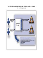
default gateway of a single router, the possibility exists for nonoptimal routing. Consider the
IP internetwork in Figure 6-8.
Figure 6-8 An ICMP Redirect scenario in which a host with a configured default gateway must
forward an IP datagram using another router
Host A, 10.0.0.99/24, is configured with the default gateway of 10.0.0.1. Host A sends an IP
datagram to Host B at 192.168.1.99. Router 1 is attached to network 10.0.0.0/24 and the rest
of the IP internetwork. Router 2 is attached to network 10.0.0.0/24 and 192.168.1.0/24.
According to the default route in Host A’s IP routing table, the next-hop address to reach the
destination 192.168.1.99 is 10.0.0.1. This is not the optimal path, however. For the optimal
path, the datagram must be forwarded to 10.0.0.2.
To inform Host A of the more optimal route for traffic to Host B at 192.168.1.99, Router 1 uses
an ICMP Redirect message. Host A uses the contents of the ICMP Redirect message to create
a host route in its routing table so that subsequent IP datagrams to Host B take the more opti-
mal route through Router 2 at 10.0.0.2.
Host B
Host A
Router 1
Router 2
192.168.1.99/24
192.168.1.0/24
10.0.0.1
10.0.0.99/24
10.0.0.2
10.0.0.0/24
Rest of
IP internetwork
Chapter 6: Internet Control Message Protocol (ICMP) 139
The following is the ICMP Redirect process in detail:
1. Host A forwards the IP datagram destined for Host B to its default gateway, Router 1, at
the IP address of 10.0.0.1.
2. Router 1 receives the IP datagram. Because the IP datagram is not destined for an IP
address assigned to Router 1, Router 1 checks the contents of its routing table for a route
to Host B. A route is found for 192.168.1.0/24 at the next-hop IP address of 10.0.0.2.
3. Before forwarding the IP datagram to Router 2 at 10.0.0.2, Router 1 notices that the
sending host’s IP address, the IP address of the interface on which the IP datagram was
received, and the next-hop IP address are all on the same network, 10.0.0.0/24.
4. Router 1 forwards the IP datagram to Router 2.
5. Router 1 sends an ICMP Redirect message to Host A. The Redirect message contains the
next-hop IP address for Router 2, 10.0.0.2, and the IP header of the discarded IP
datagram.
6. Based on the contents of the Redirect message, Host A creates a host route for the IP
address of Host B, 192.168.1.99, at the next-hop IP address of 10.0.0.2.
7. Subsequent packets from Host A to Host B are forwarded to Router 2 at the IP address
of 10.0.0.2.
ICMP Redirect messages are never sent for IP datagrams using source route options. The pres-
ence of source route options means that a specific path must be followed without regard to
whether it is optimal. Source route options are sometimes used to test connectivity along non-
optimal paths.
Figure 6-9 shows the ICMP Redirect message structure.
Figure 6-9 The structure of the ICMP Redirect message
The fields in the ICMP Redirect message are defined as follows:
■ Type Set to 5.
■ Code Set to 0–3 (see Table 6-4).
Type
Code
Checksum
Router IP Address
IP Header and first
8 bytes of datagram
=5
=0 - 3
140 Part II: Internet Layer Protocols
■ Router IP Address A 4-byte field set to the next-hop IP address for the more optimal
route to the destination of the offending IP datagram. This IP address becomes the next-
hop address for the host route created in the IP routing table.
■ IP Header + First 8 Bytes Of Forwarded Datagram To identify the forwarded IP data-
gram, the IP header and the first 8 bytes of the IP payload are encapsulated and sent
back to the sending host. Included in the encapsulated IP header is the destination IP
address for the host route.
Note
ICMP Redirect messages are sent only when the sending host forwards an IP datagram
using a nonoptimal route. ICMP Redirect messages are never sent when routers forward IP
datagrams using nonoptimal routes.
Network Monitor Capture 06-04 (in the \Captures folder on the companion CD-ROM) shows
an ICMP Echo message and the ICMP Redirect message for the example previously discussed.
Rather than adding a host route to the IP routing table, IP in Windows Server 2008 and
Windows Vista updates the route cache entry (RCE) for the destination with the Router IP
Address field as the next-hop address. The route cache stores the next-hop IP address for a
destination address, as determined by an initial routing table lookup. When sending a packet,
IP checks the route cache first, before performing a routing table lookup.
In Windows Server 2008 and Windows Vista, TCP/IP behavior for ICMP Redirect messages
can be controlled by the
netsh interface ipv4 set global icmpredirects=enabled|disabled
command. By default, support for ICMP Redirect messages is enabled. When enabled, when
a host running TCP/IP for Windows Server 2008 and Windows Vista receives an ICMP
Redirect message, it first checks the source IP address to ensure that it was sent from the
router indicated by the Gateway column for the route to the destination in the IP routing
table. TCP/IP for Windows Server 2008 and Windows Vista also ensures that the source IP
address of the ICMP Redirect is directly reachable. If the ICMP Redirect did not come from
the directly reachable indicated router, the ICMP Redirect is ignored.
You can also use the following registry value:
EnableICMPRedirect
Location: HKEY_LOCAL_MACHINE\SYSTEM\CurrentControlSet\Services\Tcpip\Parameters
Data type: REG_DWORD
Valid range: 0-1
Table 6-4 Values of the Code Field in an ICMP Redirect Message
Code Value Meaning
0 Redirected datagrams for the network (obsolete)
1 Redirected datagrams for the host
2 Redirected datagrams for the TOS and the network
3 Redirected datagrams for the TOS and the host
Chapter 6: Internet Control Message Protocol (ICMP) 141
Default: 1
Present by default: Yes
EnableICMPRedirect enables (when set to 1) and disables (when set to 0) the updating of
RCEs when an ICMP Redirect message is received. EnableICMPRedirect is enabled by default.
ICMP Router Discovery
ICMP Router Discovery is a set of ICMP messages documented in RFC 1256 that are used by
routers to advertise their presence and by hosts to discover their network segment’s routers,
and choose which router will be the host’s default gateway. ICMP Router Discovery provides
a fault-tolerance mechanism for downed routers. Hosts eventually realize that their current
default gateway has become unavailable and switch their default gateway to the next most
preferred router.
ICMP Router Discovery uses the following two different ICMP messages:
■ ICMP Router Advertisement The ICMP Router Advertisement message is sent pseudo-
periodically (at a random interval between a minimum and maximum value) by a router
to advertise its continued existence, a preference level, and a time after which it can be
considered unavailable.
■ ICMP Router Solicitation Hosts send an ICMP Router Solicitation message whenever
they need to discover the most preferred router to use as their default gateway. ICMP
Router Discovery–capable hosts that have not been configured with a default gateway
send an ICMP Router Solicitation message on startup. Additionally, hosts send an ICMP
Router Solicitation message when the availability time of their current default gateway
(discovered through ICMP Router Discovery) expires.
ICMP Router Discovery is not a routing protocol; it provides information only on a preferred
default gateway for hosts on a network segment. ICMP Router Discovery does not provide any
information on address prefixes or optimal paths.
ICMP Router Advertisement
Routers send the ICMP Router Advertisement message to either the all-hosts multicast IP
address (224.0.0.1), the subnet (or network) broadcast address, or the limited broadcast
address. ICMP Router Advertisements are sent pseudo-periodically and in response to an
ICMP Router Solicitation. The default interval for ICMP Router Advertisements is between 7
and 10 minutes. The Routing and Remote Access service implementation of ICMP Router
Discovery sends ICMP Router Advertisements to the all-hosts multicast IP address.
Figure 6-10 shows the ICMP Router Advertisement message structure.
The fields in the ICMP Router Advertisement message are defined as follows:
■ Type Set to 9.
■ Code Set to 0.
142 Part II: Internet Layer Protocols
Figure 6-10 The structure of the ICMP Router Advertisement message
■ Number Of Addresses A 1-byte field that indicates how many IP addresses are being
advertised. Normally, only a single IP address is advertised. For a router with multiple
interfaces on the same network segment, multiple IP addresses are advertised.
■ Address Entry Size A 1-byte field that indicates how many 32-bit words (4-byte quanti-
ties) are contained in a Router Advertisement entry. A Router Advertisement entry con-
sists of an IP address (32 bits) and a preference level (32 bits). Therefore, the Address
Entry Size field is always set to 2.
■ Lifetime A 2-byte field that indicates the time in seconds after the last received Router
Advertisement that the router can be considered down. This is equivalent to the Dead
Interval for the OSPF routing protocol.
■ Router IP Address A 4-byte field that indicates the IP address of the network segment’s
router interface on which the advertisement was sent.
■ Preference Level A 4-byte field that indicates the level of preference for using the Router
Address as the IP address of your default gateway. The router advertising the highest
preference level is the most preferred router. If there are two or more routers with the
same preference level, the router with the numerically smallest router address becomes
the default gateway. Router Advertisement behavior for the Routing and Remote Access
service is configured per interface through the properties of an interface in the
IPv4\General node in the Routing and Remote Access snap-in.
ICMP Router Solicitation
Hosts send the ICMP Router Solicitation message to the all-routers multicast IP address
(224.0.0.2), the subnet (or network) broadcast address, or the limited broadcast address.
Type
Code
Checksum
Number of Addresses
Address Entry Size
Lifetime
Router IP Address 1
Preference Level 1
Router IP Address n
Preference Level n
=9
=0
=2
. . .
Chapter 6: Internet Control Message Protocol (ICMP) 143
TCP/IP for Windows Server 2008 and Windows Vista listens for ICMP Router Advertisements
that are sent to the all-hosts multicast address of 224.0.0.1 and sends up to three ICMP Router
Solicitation messages spaced 600 milliseconds apart to the all-routers multicast IP address.
Figure 6-11 shows the ICMP Router Solicitation message structure.
Figure 6-11 The structure of the ICMP Router Solicitation message
The fields in the ICMP Router Solicitation message are defined as follows:
■ Type Set to 10.
■ Code Set to 0.
■ Reserved A 4-byte field that is set to 0
In Windows Server 2008 and Windows Vista, you can control TCP/IP host Router Discovery
behavior with the following command:
netsh interface ipv4 set interface
InterfaceNameOrIndex
routerdiscovery=enabled|disabled|dhcp
With the dhcp option (the default), Router Discovery is disabled but can be enabled if the
computer is a Dynamic Host Configuration Protocol (DHCP) client and the Perform Router
Discovery option (option code 31) is sent by the DHCP server.
You can also use the following registry value:
PerformRouterDiscovery
Location: HKEY_LOCAL_MACHINE\SYSTEM\CurrentControlSet\Services\ Tcpip\Parameters\Interfaces\
InterfaceGUID
Data type: REG_DWORD
Valid range: 0-2
Default: 2
Present by default: No
Set the PerformRouterDiscovery registry value to 0 to disable Router Discovery, to 1 to enable
Router Discovery, or to 2 to enable based on the Perform Router Discovery option (option
code 31) sent by the DHCP server.
The following registry value controls how TCP/IP in Windows Server 2008 and Windows
Vista sends ICMP Router Solicitation messages.
Type
Code
Checksum
Unused
=10
=0
=0
144 Part II: Internet Layer Protocols
SolicitationAddressBCast
Location: HKEY_LOCAL_MACHINE\SYSTEM\CurrentControlSet\Services\Tcpip\Parameters\Interfaces\
InterfaceGUID
Data type: REG_DWORD
Valid range: 0-1
Default: 0 (disabled)
Present by default: No
SolicitationAddressBCast enables (when set to 1) or disables (when set to 0) the use of the
subnet (or network) broadcast address as the destination IP address of ICMP Router Solicita-
tion messages. When disabled (the default), TCP/IP for Windows Server 2008 and Windows
Vista uses the all-routers IP multicast address (224.0.0.2).
ICMP Time Exceeded
The ICMP Time Exceeded message is sent in the following instances:
■ When a router decrements the IP header’s TTL field to 0 (the ICMP Time Exceeded-TTL
Exceeded in Transit message)
■ When the reassembly timer for a fragmented IP datagram expires (the ICMP Time
Exceeded-Fragment Reassembly Time Exceeded message)
When the TTL goes to 0 for an IP datagram, it can mean one of two things:
■ The IP datagram was sent with an inadequate TTL that does not reflect the current
number of links between the source and destination nodes. In this case, the TTL should
be increased.
■ A routing loop exists in the internetwork. A routing loop occurs when IP routers have
incorrect routing information and forward an IP datagram in a loop that never reaches
the destination. To test for a routing loop, send an IP datagram with a TTL of 255, the
maximum value. If an ICMP Time Exceeded-TTL Exceeded in Transit message is still
received, a routing loop exists in your internetwork.
Destination hosts receiving a fragmented IP datagram use a reassembly timer as a maximum
time to wait before discarding the incomplete IP datagram. If all of an IP datagram’s fragments
arrive within the time allotted in the reassembly timer, the IP datagram is successfully reas-
sembled. If the reassembly timer expires before all of an IP datagram’s fragments have been
received, the destination host discards the incomplete payload and can send an ICMP Time
Exceeded-Fragment Reassembly Time Exceeded message back to the source. Figure 6-12
shows the ICMP Time Exceeded message structure.
The fields in the ICMP Time Exceeded message are defined as follows:
■ Type Set to 11.
Chapter 6: Internet Control Message Protocol (ICMP) 145
Figure 6-12 The structure of the ICMP Time Exceeded message
■ Code Set to 0 or 1. Set to 0 by a router to indicate a TTL expiration (the ICMP Time
Exceeded-TTL Exceeded in Transit message). Set to 1 by a destination host to indicate a
reassembly expiration (the ICMP Time Exceeded-Fragment Reassembly Time Exceeded
message).
■ Unused A 4-byte field that is set to 0.
■ IP Header + First 8 Bytes Of Discarded Datagram To identify the discarded IP datagram,
the ICMP Time Exceeded message contains the IP header and the first 8 bytes of the
IP payload.
Network Monitor Capture 06-05 (in the \Captures folder on the companion CD-ROM) shows an
ICMP Echo message from an Internet host sent to an Internet Web site with an insufficient TTL.
ICMP Parameter Problem
A router or a destination host sends an ICMP Parameter Problem message when an error
occurs in the processing of the IP header that causes the IP datagram to be discarded, and
there are no other ICMP messages that can be used to indicate the error. ICMP Parameter
Problem messages can be sent because of errors in TCP/IP implementations causing incorrect
formatting of IP header fields. Typically, ICMP Parameter Problem messages are sent because
of incorrect arguments in IP option fields. Figure 6-13 shows the ICMP Parameter Problem
message structure.
Figure 6-13 The structure of the ICMP Parameter Problem message
Type
Code
Checksum
Unused
IP Header and first
8 bytes of datagram
=11
=0 or 1
=0
Type
Code
Checksum
Pointer
Unused
IP Header and first
8 bytes of datagram
=12
=0 - 2
=0