windows server 2008 tcp ip protocols and services microsoft 2008 phần 9 doc
Bạn đang xem bản rút gọn của tài liệu. Xem và tải ngay bản đầy đủ của tài liệu tại đây (1.42 MB, 51 trang )
376 Part IV: Application Layer Protocols and Services
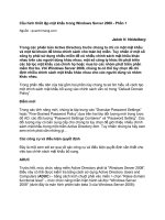
Figure 18-2 AH Transport mode
For AH Transport mode, the ICV calculation is performed over the following:
■ All the fields in the IP header except those that are allowed to change in transit. These
fields are the Type of Service (TOS), Flags, Fragment Offset, Time to Live (TTL), and
Header Checksum, all of which are set to 0 for the ICV calculation. For source-routed IP
traffic, the final destination IP address is predictable, and the appropriate fields within
the Loose Source Route and Strict Source Route options are allowed to change.
■ All the fields in the AH (the Authentication Data field is set to 0).
■ The IP packet payload.
For AH Transport mode, the AH protects the IP header, except the fields that are allowed to
change, and the payload of the original IP datagram.
The following is Frame 10 of Capture 18-01 in the \Captures folder on the companion
CD-ROM, which shows an AH-protected Domain Name System (DNS) Name Query Request
message, as displayed by Network Monitor 3.1:
Frame:
+ Ethernet: Etype = Internet IP (IPv4)
- Ipv4: Next Protocol = AH, Packet ID = 1807, Total IP Length = 86
+ Versions: IPv4, Internet Protocol; Header Length = 20
+ DifferentiatedServicesField: DSCP: 0, ECN: 0
TotalLength: 86 (0x56)
Identification: 1807 (0x70F)
+ FragmentFlags: 0 (0x0)
TimeToLive: 128 (0x80)
NextProtocol: AH, 51(0x33)
Checksum: 11405 (0x2C8D)
SourceAddress: 131.107.0.2
DestinationAddress: 131.107.0.1
IP payload
IP payload
IP header
IP header
AH
Chapter 18: Internet Protocol Security (IPsec) 377
- Ah: Next Protocol = UDP, SPI = 0x48B7D428, Seq = 0x1
NextHeader: UDP, 17(0x11)
PayloadLength: 24 bytes
Reserved: 0 (0x0)
SecurityParametersIndex: 1220006952 (0x48B7D428)
SequenceNumber: 1 (0x1)
AuthenticationData: 12 UINT8(s)
+ Udp: SrcPort = 50286, DstPort = DNS(53), Length = 42
+ Dns: QueryId = 0xDE8D, QUERY (Standard query), Query for test.contoso.com of type Host A
ddr on class Internet
AH Tunnel Mode
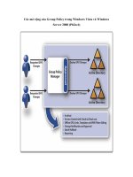
Figure 18-3 shows AH Tunnel mode for an IP datagram.
Figure 18-3 AH Tunnel mode
In AH Tunnel mode, the entire original IP datagram is encapsulated with a new (outer) IP
header and an AH. In the IP header, the Protocol field is set to 51 (0x33) to indicate that an AH
is present. For Tunnel mode, the original IP header and payload are unmodified.
The outer IP header is constructed from the configuration of the IPsec tunnel. The source IP
address is the locally assigned IP address that is the best source to reach the tunnel destina-
tion address.
For AH Tunnel mode, the ICV calculation is performed over the following:
■ All the fields in the outer IP header except those that are allowed to change in transit
(TOS, Flags, Fragment Offset, TTL, Header Checksum), all of which are set to 0 for
the calculation
■ All the fields in the AH (the Authentication Data field is set to 0)
■ The original IP packet
IP payload
IP payload
Authenticated
AH
IP header
(new)
IP header
IP header
378 Part IV: Application Layer Protocols and Services
For AH Tunnel mode, the AH protects the entire original IP packet (both the IP header and
the payload) at the expense of an additional outer IP header that is not used for AH
Transport mode.
Encapsulating Security Payload (ESP)
Encapsulating Security Payload (ESP) is a header and trailer combination defined in RFC
4303 that provides data origin authentication, data integrity, replay protection, and data con-
fidentiality for the ESP-encapsulated portion of the packet. Figure 18-4 shows the structure of
the ESP header and trailer and their location relative to the IP packet payload.
Figure 18-4 The IPsec Encapsulating Security Payload header and trailer
The ESP header consists of the following fields:
■ Security Parameters Index A 4-byte field that identifies, when used in combination with
the Destination Address field in the IP header and transform (ESP), the specific SA for
this datagram
■ Sequence Number A 4-byte field that is the same field as the Sequence Number field of
the AH
The ESP trailer consists of the following fields:
■ Padding A variable-length field (0-255 bytes) that is used to pad the encrypted payload
to an appropriate length (depending on the encryption algorithm used), align the ESP
portion of the packet along 4-byte boundaries, or deliberately obscure the encrypted
payload’s length.
■ Padding Length A 1-byte field that specifies the number of bytes in the Padding field.
Security Parameters Index
Sequence Number
Payload
Padding
Padding Length
Next Header
Authentication Data
Chapter 18: Internet Protocol Security (IPsec) 379
■ Next Header A 1-byte field used to identify the next header in the payload. This field
uses the same values as the Protocol field in the IP header.
■ Authentication Data A variable-length field that contains the ICV calculation of the
sender (the HMAC MD5 or HMAC SHA1 value).
Because the use of a specific ICV algorithm is negotiated before data with an ESP header and
trailer is sent, each peer knows the size of the Authentication Data portion of the ESP trailer
and can determine the location of the end of the ESP-encapsulated payload.
IPsec in Windows Server 2008 and Windows Vista can use the following encryption
algorithms:
■ Advanced Encryption Standard (AES) with a 128-bit key size (AES-128)
■ AES with a 192-bit key size (AES-192)
■ AES with a 256-bit key size (AES-256)
■ Triple Data Encryption Standard (3DES) with three 56-bit keys
■ Data Encryption Standard (DES) with a 56-bit key (not recommended)
The following is Frame 11 of Capture 18-02 in the \Captures folder on the companion
CD-ROM, which shows an ESP-protected DNS Name Query Request message when using
ESP and no encryption, as displayed by Network Monitor 3.1:
Frame:
+ Ethernet: Etype = Internet IP (IPv4)
- Ipv4: Next Protocol = ESP, Packet ID = 1542, Total IP Length = 88
+ Versions: IPv4, Internet Protocol; Header Length = 20
+ DifferentiatedServicesField: DSCP: 0, ECN: 0
TotalLength: 88 (0x58)
Identification: 1542 (0x606)
+ FragmentFlags: 0 (0x0)
TimeToLive: 128 (0x80)
NextProtocol: ESP, 50(0x32)
Checksum: 11669 (0x2D95)
SourceAddress: 131.107.0.2
DestinationAddress: 131.107.0.1
- Esp: Next Protocol = UDP, SPI = 0x469021eb, Seq = 0x1
SecurityParameterIndex: 1183850987 (0x469021EB)
SequenceNumber: 1 (0x1)
- Trailer:
PaddingData: Binary Large Object (2 Bytes)
PaddingLength: 2 (0x2)
NextProtocol: UDP, 17(0x11)
AuthenticationData: Binary Large Object (12 Bytes)
+ Udp: SrcPort = 50202, DstPort = DNS(53), Length = 44
+ Dns: QueryId = 0xF341, QUERY (Standard query), Query for test99.contoso.com of type Host A
ddr on class Internet
380 Part IV: Application Layer Protocols and Services
Note Network Monitor 3.1 displays the fields of the ESP trailer within the ESP header, rather
than after the ESP payload.
Network Monitor 3.1 cannot interpret the encrypted portions of an ESP-protected packet.
ESP Transport Mode
Figure 18-5 shows ESP Transport mode for an IP datagram.
Figure 18-5 ESP Transport mode
For ESP Transport mode, the ESP header is added to the IP datagram just after the IP header
and the ESP trailer is added just after the payload. In the IP header, the Protocol field is set to
50 (0x32) to indicate that an ESP header is present. Routers forward this traffic as any other
IP packet. Firewalls, on the other hand, might need to be configured to allow the forwarding
of IP protocol 50 traffic. The payload is unmodified.
Like AH, inserting an ESP header and trailer creates additional packet overhead, which lowers
the effective MTU between the two endpoints. Performing the data encryption and calculating
the ICV for the ESP trailer imposes additional processing overhead for each protected packet.
Using network adapters that can perform cryptographic calculations in hardware, also known
as offload adapters, can minimize this overhead.
For ESP Transport mode, the following portions of the packet are encrypted:
■ The payload
■ The Padding, Padding Length, and Next Header fields of the ESP trailer
Authenticated
IP payload
Encrypted
IP payload
IP header
IP header
ESP
header
ESP
trailer
Auth Data
trailer
Chapter 18: Internet Protocol Security (IPsec) 381
For encryption algorithms that use cipher block chaining (CBC), there is an unencrypted
field between the ESP header and the payload. This field is the initialization vector (IV) for the
CBC calculation performed at the receiver. This field cannot be encrypted because it is used to
begin the decryption process.
The inclusion of the IV as plaintext in the packet does not create a security problem. The IV
does not provide additional cryptographic strength, only a way to ensure that the encryption
of the same block with different IVs does not produce the same ciphertext. A malicious user
might be able to view the IV, but without the encryption key, he or she cannot decrypt the
ciphertext portion of the packet. To prevent a malicious user from modifying the IV and
causing the receiver to produce garbled deciphered data, the IV is protected by the ICV.
For ESP Transport mode, the ICV calculation is performed over the following:
■ All the fields in the ESP header
■ The payload (including the plaintext IV, if needed)
■ All the fields in the ESP trailer except the Authentication Data field
For ESP Transport mode, the ESP trailer does not provide protection for the IP header and the
Authentication Data field of the ESP trailer. To obtain protection for these elements, use both
AH and ESP, as shown in Figure 18-6.
Figure 18-6 Using both AH and ESP to protect an IP packet
With AH and ESP, the ESP header and trailer wraps the payload, which then becomes the pay-
load that is wrapped with an AH and the original IP header. Now the entire packet is protected
(except the changeable fields in the IP header).
ESP
trailer
Auth Data
trailer
IP header
IP payload
Authenticated with ESP
Authenticated with AH
Encrypted
AH
IP payload IP header
ESP
header
382 Part IV: Application Layer Protocols and Services
The following is Frame 10 of Capture 18-03 in the \Captures folder on the companion
CD-ROM, which shows an AH- and ESP-protected IP payload with ESP encryption, as
displayed by Network Monitor 3.1:
Frame:
+ Ethernet: Etype = Internet IP (IPv4)
- Ipv4: Next Protocol = AH, Packet ID = 1555, Total IP Length = 120
+ Versions: IPv4, Internet Protocol; Header Length = 20
+ DifferentiatedServicesField: DSCP: 0, ECN: 0
TotalLength: 120 (0x78)
Identification: 1555 (0x613)
+ FragmentFlags: 0 (0x0)
TimeToLive: 128 (0x80)
NextProtocol: AH, 51(0x33)
Checksum: 11623 (0x2D67)
SourceAddress: 131.107.0.2
DestinationAddress: 131.107.0.1
- Ah: Next Protocol = ESP, SPI = 0x43E235D7, Seq = 0x1
NextHeader: ESP, 50(0x32)
PayloadLength: 24 bytes
Reserved: 0 (0x0)
SecurityParametersIndex: 1138898391 (0x43E235D7)
SequenceNumber: 1 (0x1)
AuthenticationData: 12 UINT8(s)
- Esp: SPI = 0x1ef5e304, Seq = 0x1
SecurityParameterIndex: 519430916 (0x1EF5E304)
SequenceNumber: 1 (0x1)
EncryptedPayload: Binary Large Object (68 Bytes)
ESP Tunnel Mode
Figure 18-7 shows ESP Tunnel mode for an IP datagram.
Figure 18-7 ESP Tunnel mode
ESP
header
ESP
trailer
Auth Data
trailer
Authenticated
Encrypted
IP header
(new)
IP header
IP payload
IP payload IP header
Chapter 18: Internet Protocol Security (IPsec) 383
In ESP Tunnel mode, the entire original IP datagram is encapsulated with a new (outer) IP
header and an ESP header and trailer. In the outer IP header, the Protocol field is set to 50
(0x32) to indicate that an ESP header is present. For Tunnel mode, the original IP header and
payload are unmodified. Like AH Tunnel mode, the outer IP header is constructed from the
configuration of the IPsec tunnel.
For ESP Tunnel mode, the following portions of the packet are encrypted:
■ The original IP datagram (IP header and payload)
■ The Padding, Padding Length, and Next Header fields of the ESP trailer
For ESP Tunnel mode, the ICV calculation is performed over the following:
■ All the fields in the ESP header
■ The original IP datagram (IP header and payload), including the plaintext IV, if needed
■ All the fields in the ESP header except the Authentication Data field
For ESP Tunnel mode, the ESP trailer provides protection for the original IP header and pay-
load, but does not provide protection for the outer IP header and the Authentication Data
field of the ESP trailer.
IPsec and Security Associations
A security association (SA) is the combination of security services, protection mechanisms, and
cryptographic keys mutually agreed to by communicating peers. The SA contains the informa-
tion needed to determine how the traffic is to be secured (the security services and protection
mechanisms) and with which secret keys (cryptographic keys). There are two types of SAs
that are created when IPsec peers communicate securely: the Internet Security Association
and Key Management Protocol (ISAKMP) SA and the IPsec SA.
ISAKMP SA
The ISAKMP SA, also known as the main mode SA, is used to protect IPsec security negotia-
tions. The ISAKMP SA is created by negotiating the ciphersuite used for protecting future
ISAKMP traffic, exchanging key-generation material, and then identifying and authenticating
each IPsec peer.
When the ISAKMP SA is complete, all future SA negotiations for IPsec SAs are protected. This
is an aspect of secure communications known as protected ciphersuite negotiation. Not only is
the data protected, but the determination of the protection algorithms negotiated by the IPsec
peers is also protected. To break IPsec protection, a malicious user must first determine the
ciphersuite protecting the data, which represents another cryptographic barrier. For IPsec, the
384 Part IV: Application Layer Protocols and Services
exceptions to complete protected ciphersuite negotiation are the negotiations of the cipher-
suites of ISAKMP SAs, which begin as plaintext.
IPsec SA
The IPsec SA, also known as the quick mode SA, is used to protect data sent between the IPsec
peers. The IPsec SA ciphersuite negotiation is protected by the ISAKMP SA. No information
about the type of traffic or the protection mechanisms is sent as plaintext. For a pair of IPsec
peers, there are always two IPsec SAs: one is negotiated for inbound traffic and one is for out-
bound traffic. The inbound SA for one IPsec peer is the outbound SA for the other.
Security Parameters Index
For each IPsec session, IPsec peers must track the usage of three different SAs: the ISAKMP SA,
the inbound IPsec SA, and the outbound IPsec SA. To identify a specific SA, a 32-bit pseudo-
random number known as the Security Parameters Index (SPI) is used. The SPI is used for SA
management at each IPsec peer and is a field in the IPsec headers protecting IPsec traffic and
in the messages negotiating or managing SAs.
The node that initiates an IPsec negotiation to perform IPsec protection is known as the
initiator. The node that responds to a request to perform IPsec protection is known as the
responder. The initiator chooses the ISAKMP SA SPI, and each IPsec peer chooses the IPsec SA
SPI for its outbound traffic.
Creating SAs
An IPsec negotiation and determination of both ISAKMP and IPsec SAs occurs in two phases:
the Main mode phase (also known as Phase I) and the Quick mode phase (also known as
Phase II).
Main Mode Main mode negotiation creates the ISAKMP SA. The initiator and responder
exchange a series of ISAKMP messages to negotiate the ciphersuite for the ISAKMP SA (in
plaintext), exchange key determination material (in plaintext), and identify and authenticate
each other (in encrypted text). For more information about the details of Main mode negoti-
ation, see the section “Main Mode Negotiation” later in this chapter.
Quick Mode Quick mode negotiation creates the two IPsec SAs. The initiator and
responder exchange a series of ISAKMP messages to negotiate the ciphersuite for both
the inbound and outbound IPsec SAs. During Quick mode negotiation, keying material is
refreshed or, if necessary, new keys are generated. For more information about the details
of quick mode negotiation, see the section “Quick Mode Negotiation” later in this chapter.
For IPsec for Windows Server 2008 and Windows Vista, a complete IPsec negotiation includ-
ing both Main mode and Quick mode requires either 9 or 10 ISAKMP messages exchanged
between IPsec peers, depending on security settings.
Chapter 18: Internet Protocol Security (IPsec) 385
Internet Key Exchange
The Internet Key Exchange (IKE) is a standard that defines a mechanism to establish SAs.
IKE, described in RFC 2409, combines ISAKMP and the Oakley Key Determination Protocol.
IPsec uses the ISAKMP protocol to negotiate SAs. ISAKMP includes facilities to identify and
authenticate peers, manage SAs, and exchange key material. ISAKMP is a framework for nego-
tiating secure communications independent of specific key exchange protocols, encryption
and integrity algorithms, and authentication methods.
To generate secret key material for secure communications, IKE uses the Oakley Key Determi-
nation Protocol. Oakley is based on the Diffie-Hellman key exchange algorithm, which allows
two peers to determine a secret key by exchanging unencrypted values over a public network.
The mutually determined secret key becomes keying material from which secret keys for
HMAC or encryption algorithms are derived.
More Info
The details of the Diffie-Hellman algorithm and the Oakley protocol are outside
the scope of this book, but they are described in RFC 2412.
ISAKMP Message Structure
ISAKMP messages are sent as the payload of UDP messages using UDP port 500. Figure 18-8
shows the format of an ISAKMP message.
Figure 18-8 An ISAKMP message
The ISAKMP message consists of an ISAKMP header and one or more ISAKMP payloads. The
ISAKMP payloads contain negotiation information and are encrypted for most ISAKMP mes-
sages. The encryption protects the negotiation from being viewed by malicious users who are
capturing ISAKMP traffic. The encrypted portions of ISAKMP messages cannot be viewed
with Network Monitor. ISAKMP is defined in RFC 2408.
ISAKMP Header
The ISAKMP header is a standard header that is present for all ISAKMP messages and con-
tains information about the message, including the type of packet. Figure 18-9 shows the for-
mat of the ISAKMP header.
IP datagram
UDP message
ISAKMP payloads
UDP
header
ISAKMP
header
IP header
386 Part IV: Application Layer Protocols and Services
Figure 18-9 The ISAKMP header.
The fields in the ISAKMP header are defined as follows:
■ Initiator Cookie An 8-byte field that is set to a nonzero random number chosen by the
IPsec peer that initiated the SA, is performing a notification about an existing SA, or is
deleting the SA.
■ Responder Cookie An 8-byte field that is set to a nonzero random number chosen by
the IPsec peer responding to the peer that initiated an SA.
■ Next Payload A 1-byte field that indicates the type of the payload that follows the
ISAKMP header. Table 18-1 lists the payload types defined in RFC 2408.
Table 18-1 Values of the Next Payload Field
Next Payload Value Next Payload Type
0None
1SA
2Proposal
3Transform
4Key Exchange
5 Identification
6 Certificate
7 Certificate Request
8Hash
9Signature
10 Nonce
11 Notification
12 Delete
13 Vendor ID
Initiator Cookie
Responder Cookie
Next Payload
Major Version
Minor Version
Exchange Type
Flags
Message ID
Length
Chapter 18: Internet Protocol Security (IPsec) 387
■ Major Version A 4-bit field that indicates the major version of the ISAKMP protocol for
this message. This field must be set to 1 if the implementation complies with RFC 2408.
ISAKMP messages with a higher supported major version number are discarded.
■ Minor Version A 4-bit field that indicates the minor version of the major version of the
ISAKMP protocol for this message. This field must be set to 0 if the implementation
complies with RFC 2408. ISAKMP messages with a higher supported minor version
number are discarded, within the same supported major version.
■ Exchange Type A 1-byte field that indicates the type of ISAKMP exchange being per-
formed for this ISAKMP message. The type of exchange dictates the structure and the
order of ISAKMP payloads. Table 18-2 lists the exchange types defined in RFC 2408.
■ Flags A 1-byte field containing ISAKMP flags that are set for this ISAKMP message.
There are three flags defined in RFC 2408. The low-order bit (bit 0) is the Encryption
bit, which indicates the ISAKMP payloads are encrypted (when set to 1) or not
encrypted (when set to 0). Encryption is done using the algorithm negotiated for
the ISAKMP SA, which is identified by the combination of the Initiator Cookie and
Responder Cookie fields. The next low-order bit (bit 1) is the Commit bit, which indi-
cates that the key exchange is synchronized (when set to 1) or not synchronized (when
set to 0). The Commit bit is used to ensure that the SA completes its negotiation before
encrypted data is sent. The next low-order bit (bit 2) is the Authentication Only bit,
which is used to indicate that the message either contains (when set to 1) or does not
contain (when set to 0) the entire Notify payload of the informational exchange type
and it has been authenticated but not encrypted. For more information, see the section
“Notification Payload” later in this chapter.
14–127 Reserved
128–255 Private Use
Table 18-2 Values of the Exchange Type Field
Exchange Type Value Exchange Type
0None
1Base
2Identity Protection
3 Authentication Only
4 Aggressive
5Informational
6–31 ISAKMP Future Use
32–239 DOI Specific Use
240–255 Private Use
Table 18-1
Values of the Next Payload Field
Next Payload Value Next Payload Type
388 Part IV: Application Layer Protocols and Services
■ Message ID A 4-byte field that contains a unique identifier for the message. The
Message ID is used to prevent collisions due to both IPsec peers attempting to simulta-
neously establish an IPsec SA. The Message ID field is set to 0 for the ISAKMP SA estab-
lishment.
■ Length A 4-byte field that indicates the length of the entire ISAKMP message.
SA Payload
The SA payload is used to indicate the domain of interpretation (DOI) and situation for the SA
negotiation. The DOI is a set of definitions for payload formats, exchange types, and naming
conventions for security-related information, such as the naming of policies and crypto-
graphic algorithms. A situation is a set of information that identifies security services in the
ISAKMP message. Figure 18-10 shows the format of the SA payload.
Figure 18-10 The SA payload
The fields in the SA payload are defined as follows:
■ Next Payload A 1-byte field that indicates the next payload in the message. Next Pay-
load is set to 0 for the last payload in the message. For the SA payload, the Next Payload
field does not indicate the Proposal or Transform payloads because they are considered
part of the SA payload.
■ Reserved A 1-byte field set to 0.
■ Payload Length A 2-byte field that indicates the length of the payload. For the SA
payload, the length includes the Proposal and Transform payloads.
■ Domain of Interpretation A 4-byte field that indicates the DOI. For IPsec and ISAKMP,
the DOI field is set to 1. RFC 2407 describes the IPsec DOI for ISAKMP.
■ Situation A variable-length field that identifies the situation for the negotiation. For
IPsec, the values of the Situation field are defined in RFC 2407. For example, the Situa-
tion field is set to 1 for SIT_IDENTITY_ONLY, a situation that specifies that the identity
of the sending source is contained in an Identification payload. See section 4 of RFC
2407 for additional situation definitions.
Next Payload
Reserved
Payload Length
Domain of Interpretation
Situation
Chapter 18: Internet Protocol Security (IPsec) 389
Note The Next Payload, Reserved, and Payload Length fields are common to all ISAKMP
payloads. Therefore, they are not described in the payload sections that follow unless there are
additional considerations for their use.
Proposal Payload
The Proposal payload contains security parameter information that is used to negotiate the
security settings for either an ISAKMP or IPsec SA. The Proposal payload contains proposal
settings and then a series of one or more Transform payloads that contain the specific security
settings for encryption and authentication algorithms for the SA. Figure 18-11 shows the
format of the Proposal payload.
Figure 18-11 The Proposal payload
The fields in the Proposal payload are defined as follows:
■ Next Payload For the Proposal payload, the Next Payload field must be set to either 2
for additional Proposal payloads or 0 for no more Proposal payloads.
■ Payload Length For the Proposal payload, the Payload Length field indicates the length
of the entire Proposal payload, which includes the Transform payloads for this Proposal
payload.
■ Proposal Number A 1-byte field that indicates the number of this proposal.
■ Protocol-ID A 1-byte field that specifies the security protocol suite being negotiated,
such as ISAKMP (Protocol-ID is set to 1). For a current list, see
/assignments/isakmp-registry.
■ SPI Size A 1-byte field that indicates the length in bytes of the optional SPI field. If the
protocol indicated by the Protocol-ID field does not use a SPI, SPI size is set to 0. For
example ISAKMP does not use a SPI.
Next Payload
Reserved
Payload Length
Proposal Number
Protocol-ID
SPI Size
Number of Transforms
SPI
390 Part IV: Application Layer Protocols and Services
■ Number of Transforms A 1-byte field that indicates the number of Transform payloads
for this proposal.
■ SPI A variable-size field that contains the SPI. This field is only present if the SPI Size
field is greater than 0.
Transform Payload
The Transform payload contains information that identifies a specific security mechanism,
or transform, that is proposed to secure future traffic. The Transform payload also contains
SA attributes, as defined in RFC 2407 for the IPsec DOI. Figure 18-12 shows the Transform
payload.
Figure 18-12 The Transform payload
The fields in the Transform payload are defined as follows:
■ Next Payload For the Transform payload, the Next Payload field must be set to either
3 for additional Transform payloads or 0 for no more Transform payloads for this
proposal.
■ Payload Length For the Transform payload, the Payload Length field indicates the
length of the entire Transform payload, which includes the SA attributes for this
Transform payload.
■ Transform Number A 1-byte field that indicates the number of this transform.
■ Transform ID A 1-byte field that indicates the Transform identifier for the protocol of
the proposal. Transform IDs are defined in RFC 2407 for the IPsec DOI.
■ Reserved2 A 2-byte field that is set to 0.
■ SA Attributes Variable-length fields that define the SA attributes for the transform. SA
attributes are either in type-value or type-length (2 bytes)-value (TLV) format. In both
cases, the Type field is 2 bytes in length. To distinguish type-value from TLV format, the
high-order bit of the Attribute Type field is set to 1 for type-value format and 0 for TLV
format. SA attributes for the IPsec DOI are defined in section 4.5 of RFC 2407.
Next Payload
Reserved
Payload Length
Transform Number
Transform ID
Reserved2
SA Attributes
Chapter 18: Internet Protocol Security (IPsec) 391
The following is Frame 1 of Capture 18-01 in the \Captures folder on the companion
CD-ROM, which shows the relationship among the SA, Proposal, and Transform payloads,
and the SA attributes within a Transform payload as displayed by Network Monitor 3.1:
Frame:
+ Ethernet: Etype = Internet IP (IPv4)
+ Ipv4: Next Protocol = UDP, Packet ID = 1517, Total IP Length = 236
+ Udp: SrcPort = ISAKMP/IKE(500), DstPort = ISAKMP/IKE(500), Length = 216
- Ike: version = 1.0, Identity protection (Main Mode), Flags = , Length = 208
InitiatorCookie: D8 22 8F 25 FE 3F DB D8
ResponderCookie: 47 46 01 F9 67 63 0F 11
NextPayload: Security Association (SA), 1(0x01)
+ Version: 1.0
ExchangeType: Identity protection (Main Mode), 2(0x02)
+ FlagsVer1:
MessageID: 0 (0x0)
Length: 208 (0xD0)
- SecurityAssociation: Next Payload = Vendor ID (VID), Length = 56
NextPayload: Vendor ID (VID), 13(0x0D)
Reserved: 0 (0x0)
PayloadLength: 56 (0x38)
DOI: IPSEC(1)
+ Situation: SIT_IDENTITY_ONLY
- ProposalPayload: Next Payload = None, ProtocolID = ISAKMP, NumberOfTransforms = 1,
Length = 44
NextPayload: None, 0(0x00)
Reserved: 0 (0x0)
PayloadLength: 44 (0x2C)
Proposal: 1 (0x1)
ProtocolID: ISAKMP, 1(0x01)
SPISize: 0 (0x0)
NumberOfTransforms: 1 (0x1)
- TransformPayload: Next Payload = None, TransformID = KEY_IKE, Length = 36
NextPayload: None, 0(0x00)
Reserved: 0 (0x0)
PayloadLength: 36 (0x24)
Transform: 1 (0x1)
TransformId: KEY_IKE 1(0x01)
RESERVED2: 0 (0x0)
+ Attribute: TV: basic Encryption algorithm = 3DES-CBC
+ Attribute: TV: basic Hash algorithm = SHA
+ Attribute: TV: basic Group description = Alternate 1024-bit MODP group
+ Attribute: TV: basic Authentication method = Pre-shared key (PSK)
+ Attribute: TV: basic Life type = seconds
+ Attribute: TLV: variable Life duration = Binary Large Object (4 Bytes)
+ VendorID: MS NT5 ISAKMPOAKLEY, Version 6, Next Payload = Vendor ID (VID), Length = 24
+ VendorID: RFC 3947 (NAT-T supported), Next Payload = Vendor ID (VID), Length = 20
+ VendorID: draft-ietf-ipsec-nat-t-ike-02, Next Payload = Vendor ID (VID), Length = 20
+ VendorID: FRAGMENTATION, Next Payload = Vendor ID (VID), Length = 20
+ VendorID: 0xfb1de3cdf341b7ea16b7e5be0855f120, Next Payload = Vendor ID (VID), Length =
20
+ VendorID: IKE CGA version 1, Next Payload = None, Length = 20
392 Part IV: Application Layer Protocols and Services
Vendor ID Payload
The Vendor ID payload contains a string or number that either indicates a specific capability
or is defined by a vendor so that an IPsec implementation can recognize an IPsec peer running
the same implementation. IPsec peers are not required to run the same implementation or
support the same capabilities, so the sending of Vendor ID payloads and the actions taken
when they are received are optional. If a receiver recognizes the Vendor ID, it can make use of
the capability or use private payloads, which use the Payload ID numbers 128 through 255.
For vendor identification, the Vendor ID value must be unique and is typically a hash of well-
known text chosen by the designers of an IPsec implementation. For capability identification,
the Vendor ID value must be unique and is typically chosen by the designers of the IPsec
capability.
Figure 18-13 shows the format of the Vendor ID payload.
Figure 18-13 The Vendor ID payload
The only field in the Vendor ID payload (besides the Next Header, Reserved, and Payload
Length fields) is the Vendor ID field, a variable-length field that contains the Vendor ID value.
IPsec for Windows Server 2008 and Windows Vista uses the following Vendor ID payloads to
indicate that the IPsec peer:
■ Is running a Microsoft operating system and the version of that operating system
■ Supports Network Address Translator (NAT) Traversal capability based on RFC 3947
■ Supports Network Address Translator (NAT) Traversal capability based on the
draft-ietf-ipsec-nat-t-ike-02.txt Internet draft
■ Supports fragmentation
■ Supports network load balancing
■ Supports Authenticated Internet Protocol (AuthIP)
■ Supports Kerberos authentication using the Generic Security Services Application
Programming Interface (GSSAPI)
■ Supports IKE with IPv6 Cryptographically Generated Addresses (CGA)
■ Supports Negotiation Discovery
Next Payload
Reserved
Payload Length
Vendor ID
Chapter 18: Internet Protocol Security (IPsec) 393
Negotiation Discovery is new behavior for Windows Server 2008 and Windows Vista to
automatically determine whether a potential peer supports IPsec. The Negotiation Discovery
Vendor ID payload is shown in Network Monitor 3.1 as Vendor ID
0xFB1DE3CDF341B7EA16B7E5BE0855F120.
The Network Load Balancing Vendor ID payload is shown in Network Monitor 3.1 as Vendor
ID Vid-Initial-Contact.
Nonce Payload
The Nonce payload contains a pseudorandom number that is used to ensure a live exchange
and provide replay protection. Nonces are also used to calculate hashes in other payloads.
Figure 18-14 shows the format of the Nonce payload.
Figure 18-14 The Nonce payload
The only field in the Nonce payload (besides the Next Header, Reserved, and Payload Length
fields) is the Nonce Data field, a variable-length field that contains the pseudorandom num-
ber determined by the sender of the ISAKMP message.
Key Exchange Payload
The Key Exchange payload contains information pertaining to the key exchange process.
The key exchange process supported by IPsec for Windows Server 2008 and Windows Vista
is Diffie-Hellman. With Diffie-Hellman, two IPsec peers exchange key values that are sent in
plaintext. From the key values, each IPsec peer calculates the same private key. With the
Diffie-Hellman exchange, a malicious user between the IPsec peers can view the exchanged
key values but cannot easily calculate the same result as the IPsec peers. Figure 18-15 shows
the format of the Key Exchange payload.
Figure 18-15 The Key Exchange payload
Next Payload
Reserved
Payload Length
Nonce Data
Next Payload
Reserved
Payload Length
Key Exchange Data
394 Part IV: Application Layer Protocols and Services
The only field in the Key Exchange payload (besides the Next Header, Reserved, and Payload
Length fields) is the Key Exchange Data field, a variable-length field that contains the key
exchange value determined by the sender of the ISAKMP message.
Notification Payload
The Notification payload is used to transmit control information, such as an error condition,
to an IPsec peer. A single ISAKMP message can contain multiple Notification payloads. For
Notification payloads within a Main mode message, the initiator and responder cookies iden-
tify the negotiation. Figure 18-16 shows the format of the Notification payload.
Figure 18-16 The Notification payload
The fields in the Notification payload are defined as follows:
■ Domain of Interpretation A 4-byte field that identifies the DOI for the notification. For
the ISAKMP DOI, the value is 0; for the IPsec DOI, the value is 1.
■ Protocol-ID A 1-byte value that indicates the protocol to which the notification applies.
■ SPI Size A 1-byte field that indicates the length of the SPI field. For ISAKMP, the secu-
rity identifier is the initiator/responder cookie pair. Therefore, the SPI Size field can be
set to 0. For ISAKMP, if the SPI Size field is set to a non-zero value, the SPI field is
ignored.
■ Notify Message Type A 2-byte field that specifies the type of notification message.
■ SPI A variable-length field that specifies the SPI for the notification.
■ Notification Data A variable-length field that contains additional information or text
for the notification message indicated by the Notify Message Type field.
Next Payload
Reserved
Payload Length
Domain of Interpretation
Protocol-ID
SPI Size
Notify Message Type
SPI
Notification Data
Chapter 18: Internet Protocol Security (IPsec) 395
Table 18-3 lists some of the notification error messages specified in RFC 2408. For a complete
list, see section 3.14.1 of RFC 2408.
Table 18-4 lists some of the notification status messages specified in RFC 2408.
Delete Payload
The Delete payload is used to inform an IPsec peer that an SA for a specific protocol has been
deleted. The receiver should remove its corresponding SA. IPsec for Windows Server 2008
and Windows Vista supports verification of Delete payloads. If an ISAKMP message with a
Delete payload is received, the receiver acknowledges it. If an acknowledgment is not received,
the Delete payload is resent. Figure 18-17 shows the format of the Delete payload.
Figure 18-17 The Delete payload
Table 18-3
Notification Error Messages
Notification Message Type Value Notification Message
1 INVALID-PAYLOAD-TYPE
2 DOI-NOT-SUPPORTED
3 SITUATION-NOT-SUPPORTED
4 INVALID-COOKIE
5 INVALID-MAJOR-VERSION
6 INVALID-MINOR-VERSION
Table 18-4
Notification Status Messages
Notification Message Type Value Notification Message
16384 CONNECTED
16385–24575 RESERVED (Future Use)
24576–32767 DOI-specific codes
32768–40959 Private Use
40960–65535 RESERVED (Future Use)
Next Payload
Reserved
Payload Length
Domain of Interpretation
Protocol-ID
SPI Size
Number of SPIs
SPIs
396 Part IV: Application Layer Protocols and Services
The fields in the Delete payload are defined as follows:
■ Domain of Interpretation A 4-byte field that identifies the DOI. The DOI is 0 for
ISAKMP and 1 for IPsec.
■ Protocol-ID A 1-byte field that identifies the protocol for the SA that was deleted. The
Protocol-ID field indicates ISAKMP for main mode SA deletions and ESP or AH for
Quick mode SA deletions.
■ SPI Size A 1-byte field that indicates the length of a SPI in the SPIs field. For the
ISAKMP protocol, the SPI size is set to 16.
■ Number of SPIs A 2-byte field that indicates the number of SPIs in the SPIs field.
■ SPIs A variable-length field that identifies the SAs to delete. All of the SPIs have the
same length, as indicated with the SPI Size field.
Identification Payload
The Identification payload is used to convey identification information and authenticate an
IPsec peer.
Figure 18-18 shows the format of the Identification payload.
Figure 18-18 The Identification payload
The fields in the Identification payload are defined as follows:
■ ID Type A 1-byte field that indicates the type of identification.
■ DOI-Specific ID Data A 3-byte field that contains DOI-specific data. If not used, this is
set to 0.
■ Identification Data A variable-length field that contains identity information.
Hash Payload
The Hash payload contains a hash value that is a result of a hash function computed over a set
of fields or other parameters. The Hash payload can be used to provide integrity or authenti-
cation of negotiating peers. Figure 18-19 shows the format of the Hash payload.
Next Payload
Reserved
Payload Length
ID Type
DOI-Specific ID Data
Identification Data
Chapter 18: Internet Protocol Security (IPsec) 397
Figure 18-19 The Hash payload
The only field in the Hash payload (besides the Next Header, Reserved, and Payload Length
fields) is the Hash Data field, a variable-length field that contains the hash value. Both IPsec
peers must agree to the set of fields or other parameters over which the hash is calculated.
Certificate Request Payload
The Certificate Request payload is used to request certificates from an IPsec peer. After receipt
of an ISAKMP message with a Certificate Request payload, an IPsec peer must send a certifi-
cate or certificates based on the contents of the Certificate Request payload. Figure 18-20
shows the format of the Certificate Request payload.
Figure 18-20 The Certificate Request payload
The fields in the Certificate Request payload are defined as follows:
■ Certificate Type A 1-byte field that indicates the type of the certificate requested.
Table 18-5 lists the certificate types defined in RFC 2408.
Next Payload
Reserved
Payload Length
Hash Data
Table 18-5 Certificate Type Values
Certificate Type Value Certificate Type
0None
1 Public Key Cryptography Standards (PKCS) #7 wrapped X.509 Certificate
2 Pretty Good Privacy (PGP) Certificate
3 Domain Name System (DNS) Signed Key
4 X.509 Certificate: Signature
5 X.509 Certificate: Key Exchange
6Kerberos Tokens
7 Certificate Revocation List (CRL)
Next Payload
Reserved
Payload Length
Certificate Type
Certificate Authority
398 Part IV: Application Layer Protocols and Services
■ Certificate Authority A variable-length field that contains an acceptable certification
authority (CA) for the indicated type of certificate. For example, for an X.509 certificate,
the distinguished name of the issuing CA is used. If there is no specific CA required by
the sending IPsec peer, this field is not present.
Certificate Payload
The Certificate payload is used by an IPsec peer when sending its certificate. This is typically
done during the authentication phase of Main mode negotiation. Figure 18-21 shows the for-
mat of the Certificate payload.
Figure 18-21 The Certificate payload
The fields in the Certificate payload are defined as follows:
■ Certificate Encoding A 1-byte field that indicates the method for encoding the certifi-
cate information in the Certificate Data field. Table 18-5 lists the values of the Certificate
Encoding field defined in RFC 2408. The same values for the Certificate Type field of the
Certificate Request payload are used for the Certificate Encoding field in the Certificate
payload.
■ Certificate Data A variable-length field that contains the encoding of the certificate
using the encoding method indicated in the Certificate Encoding field.
Signature Payload
The Signature payload is used to send digital signatures calculated over a set of fields or
parameters. The Signature payload provides data integrity and nonrepudiation services dur-
ing the authentication phase of Main mode negotiation. Figure 18-22 shows the format of the
Signature payload.
8 Authority Revocation List (ARL)
9 Simple Public Key Infrastructure (SPKI) Certificate
10 X.509 Certificate: Attribute
11–255 Reserved
Table 18-5
Certificate Type Values
Certificate Type Value Certificate Type
Next Payload
Reserved
Payload Length
Certificate Encoding
Certificate Data
Chapter 18: Internet Protocol Security (IPsec) 399
Figure 18-22 The Signature payload
The only field in the Signature payload (besides the Next Header, Reserved, and Payload
Length fields) is the Signature Data field, a variable-length field that contains the digital sig-
nature value. Both IPsec peers must agree on the set of fields and parameters over which the
digital signature is calculated.
Main Mode Negotiation
Main mode negotiation determines encryption key material and security protection for use in
protecting subsequent Main mode or Quick mode communications. Main mode negotiation
occurs in the following steps:
1. Negotiation of protection suites
2. A Diffie-Hellman exchange
3. Authentication
Main mode negotiation consists of either five or six ISAKMP messages: three sent by the initi-
ator and two or three sent by the responder. For examples of main mode negotiation, see the
following:
■ Frames 1–5 of Capture 18-01 in the \Captures folder on the companion CD-ROM
(Frames 4 and 5 have encrypted ISAKMP payloads)
■ Frames 1–6 of Capture 18-02 (Frames 5 and 6 have encrypted ISAKMP payloads)
■ Frames 1–5 of Capture 18-03 (Frames 4 and 5 have encrypted ISAKMP payloads)
Quick Mode Negotiation
When the Main mode negotiation is complete, each IPsec peer has selected a specific set of
cryptographic algorithms for securing Main mode and Quick mode messages, exchanged key
information to derive a shared secret key, and performed authentication. Before secure data is
sent, a Quick mode negotiation must occur to determine the type of traffic to be secured and
how it will be secured. A Quick mode negotiation is also done when a Quick mode SA expires.
Quick mode messages are ISAKMP messages that are encrypted using the ISAKMP SA. The
result of a Quick mode negotiation is two IPsec SAs: one for inbound traffic and one for out-
bound traffic.
Next Payload
Reserved
Payload Length
Signature Data
400 Part IV: Application Layer Protocols and Services
Quick mode negotiation for IPsec for Windows Server 2008 and Windows Vista consists of
four ISAKMP messages. The first Quick mode ISAKMP message, sent by the initiator, contains
the following payloads:
■ SA The SA payload contains a list of proposals and encryption and hashing algorithms
for how to secure the traffic (AH versus ESP, AES versus 3DES, and MD5 versus SHA1)
and a description of the traffic that is protected (IP addresses, IP Protocol numbers, TCP
ports, UDP ports, and so on).
■ Identification The Identification payload contains a description of the traffic to be
secured.
■ Nonce The Nonce payload contains a pseudorandom number to be used in subse-
quent hash calculations.
The second Quick mode ISAKMP message, sent by the responder, contains the following
payloads:
■ SA The SA payload contains a Proposal payload, which contains a single Transform
payload corresponding to the protection suite that was offered by the initiator in the
first Quick mode message and is acceptable to the responder for the traffic to be
secured.
■ Identification The Identification payload contains a description of the traffic to be
secured.
■ Nonce The Nonce payload contains a pseudorandom number to be used in subse-
quent hash calculations.
The second message has the Commit bit in the ISAKMP header set.
The third Quick mode ISAKMP message, sent by the initiator, contains the Hash payload,
which contains a hash value to provide verification and replay protection.
The fourth Quick mode ISAKMP message, sent by the responder, contains the Notification
payload, which contains the Notify Message Type set to 16384 (the CONNECTED status
message), indicating that the SA negotiation is complete.
The setting of the Commit bit in Quick mode message 2 and the sending of the CONNECTED
status message in Quick mode message 4 are not required by the ISAKMP or IKE standards.
IPsec for Windows Server 2008 and Windows Vista uses this facility to prevent the initiator
from sending IPsec-protected packets to the responder before the responder is ready to
receive them.
For examples of quick mode negotiation, see the following:
■ Frames 6–9 of Capture 18-01 in the \Captures folder on the companion CD-ROM (all of
these frames have encrypted ISAKMP payloads)