Mobile Communication System Evolution
Bạn đang xem bản rút gọn của tài liệu. Xem và tải ngay bản đầy đủ của tài liệu tại đây (475.55 KB, 42 trang )
Mobile Satellite Communication Networks. Ray E. Sheriff and Y. Fun Hu
Copyright q 2001 John Wiley & Sons Ltd
ISBNs: 0-471-72047-X (Hardback); 0-470-845562 (Electronic)
1
Mobile Communication
System Evolution
1.1 Historical Perspective
The mobile phone has proved to be one of the most outstanding technological and commercial successes of the last decade. Since its introduction in the 1980s, the phone’s place in the
market place has rapidly progressed from a minority, specialised item to virtually an essential
commodity for both business and leisure use. Over the last two decades, advances in mobile
technology, combined with the significant reduction in operating costs and the development
of new applications and services, have ensured a buoyant market. By mid-2000, there were
over 220 million mobile subscribers in Europe and over 580 million mobile subscribers
world-wide. In the UK, every other person owns a mobile phone; while in Finland the number
of mobile phones per capita now exceeds that of households with fixed phone lines.
As with most technological innovations, the mobile phone’s marketability is not based on
overnight success but rather a systematic, evolutionary development involving multi-national
co-operation at both technical and political levels. In fact, the concept of a mobile phone is
not new. As early as 1947, the cellular concept was discussed within Bell Laboratories [YOU79]. However, it was not until the 1970s that technology had developed sufficiently to allow
the commercial implementation of such a system to be investigated.
The evolution of mobile communications can be categorised into generations of development. Presently, we are on the verge of the third-generation (3G) of mobile systems. Broadly
speaking, first-generation (1G) systems are those that paved the way and are generally
categorised as being national networks that are based on analogue technology. Such networks
were introduced into service in the 1980s. These networks were designed to provide voice
communications to the mobile user.
Second-generation (2G) systems are categorised by digital technology. They are supported
by international roaming agreements, allowing the possibility to operate a mobile phone across
national boundaries. With the introduction of 2G systems, in addition to digital voice telephony, a new range of low data rate digital services became available, including mobile fax,
voice mail and short message service (SMS) [PEE-00]. Also at this stage in the evolution, new
types of systems began to emerge which catered for particular market needs; not only cellular
mobile, but also cordless, public mobile radio, satellite and wireless-local area network (WLAN) solutions. 2G systems are synonymous with the globalisation of mobile systems, and in
Mobile Satellite Communication Networks
2
this respect the importance of standardisation is clear. For example, GSM, which was standardised in Europe by the European Telecommunications Standards Institute (ETSI), is now
recognised as a global standard, with its adoption in most countries of the world. The final
evolutionary phase of 2G networks, in recognition of the importance of the Internet and as a
stepping stone towards the introduction of 3G technology, introduced packet-oriented services,
providing the first opportunity to introduce mobile-multimedia services.
Within the next few years, it is expected that mobile users will wish to access broadband
multimedia services, such as those provided by fixed networks. This demand for broader
bandwidth services is driven by the need to provide services and applications comparable
with those presently available to personal computers (PCs). The phenomenal growth in the
Internet, with over 500 million users predicted by 2005, perfectly illustrates the need for
access to broadband services and applications. These types of services are beyond the
capability of present 2G systems, which offer voice and low data rate services. The convergence of mobile and Internet protocol (IP) based technologies is now the major driving force
behind the development of 3G systems. The 3G mobile communications systems will be
capable of delivering services and applications at data rates of up to and beyond 2 Mbit/s.
The standardisation of 3G systems comes under the overall responsibility of the International Telecommunication Union (ITU). Globally, this will be known as international mobile
telecommunications 2000 (IMT-2000) and will consist of a family systems providing cellular, cordless, W-LAN and satellite services. In Europe, the 3G system will be known as the
Universal Mobile Telecommunications System (UMTS). Although voice is still likely to be
the dominant application in the first few years of 3G networks, there will also be the possibility to operate mobile-multimedia applications, such as video-telephony, file transfer protocol (ftp) file access, Web browsing and so on. As 3G technology evolves, new broader
bandwidth applications will enter the market to such an extent that the transmission of
data will provide the greatest volume of traffic.
Research is now addressing the requirements of fourth-generation (4G) mobile networks.
Mobile data rates beyond 2 Mbit/s, and possibly up to 155 Mbit/s in some environments, will
further extend the services and applications that could be delivered. Improvements in quality
of service (QoS), bandwidth efficiency and the move to an all IP-based, packet-oriented
environment can be envisaged, based on the emerging standards of Mobile IP, under development by the Internet Engineering Task Force (IETF) [PER-98, SOL-98]. 4G mobile
networks are likely to be introduced sometime after 2005, possibly as late as 2010.
Although this book is primarily focused on mobile-satellite networks, initially in order to
appreciate the context in which satellite technologies have developed, and the likely applications for such technologies, it is important to have an understanding of where we are at
present in terms of mobile technology. This chapter aims to provide a flavour of the underlying technological developments that have driven the mobile communication industry to the
brink of the establishment of the mobile information society.
1.2
Cellular Systems
1.2.1 Basic Concepts
Cellular networks operate by dividing the service coverage area into zones or cells, each of
which has its own set of resources or channels, which can be accessed by users of the network.
Mobile Communication System Evolution
3
Usually cellular coverage is represented by a hexagonal cell structure to demonstrate the
concept, however, in practice the shape of cells is determined by the local topography.
Sophisticated planning tools are used extensively by terrestrial cellular operators to assist
with the planning of their cellular networks.
The shape and boundary of a cell is determined by its base station (BS), which provides the
radio coverage. A BS communicates with mobile users through signalling and traffic channels
(TCH). Signals transmitted in the direction from the BS to the mobile are termed the forward
link or downlink, and conversely, the reverse link or uplink is in the direction of mobile to BS.
Signalling channels are used to perform administrative and management functions such as
setting up a call, while TCHs are used to convey the information content of a call. The
allocation of channels to a cell is therefore divided between the TCHs, which form the
majority, and signalling channels. These are allocated for both forward and reverse directions.
In order to increase the capacity of a network, there are three possibilities, either:
1. a greater number of channels are made available;
2. more spectrally efficient modulation and multiple access techniques are employed; or
3. the same channels are re-used, separated by a distance which would not cause an unacceptable level of co-channel interference.
Cellular networks, which are limited in terms of available bandwidth, operate using the
principal of frequency re-use. This implies that the same pool of frequencies is re-used in cells
that are sufficiently separated so as not to cause harmful co-channel interference. For a
hexagonal cell structure, it is possible to cluster cells so that no two adjacent cells are
using the same frequency. This is only achievable for certain cell-cluster sizes, which can
be determined from the relationship
N ẳ i2 1 ij 1 j2
1:1ị
where i, j ¼ 0, 1, 2, 3, etc.
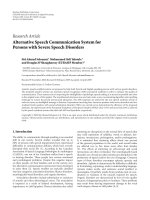
A seven-cell frequency re-use pattern is shown in Figure 1.1. The total bandwidth available
to the network is divided between cells in a cluster, which can then be used to determine the
number of calls that can be supported in each cell. By reducing the number of cells per cluster,
the system capacity can be increased, since more channels can be available per cell. However,
a reduction in the cluster size will also result in a reduction in the frequency re-use distance,
hence the system may become more prone to co-channel interference.
The frequency re-use distance can be determined for a given cell cluster size from the
equation
p
D
ẳ 3N
1:2ị
R
where D is the mean re-use distance, R is the cell radius and N is the cluster size.
In a terrestrial mobile radio environment, the strength of the received carrier power, at a
distance R from the transmitter is related by the following expression:
C/
1
Rg
ð1:3Þ
where g is a constant related to the terrain environment, usually assumed to be equal to 4.
Mobile Satellite Communication Networks
4
Figure 1.1
Seven-cell frequency re-use pattern.
For a seven-cell re-use configuration, the ratio of the carrier-to-interference experienced by
a mobile from the six cells located at a minimum re-use distance of D from the mobile, that is
on the first tier of the cell cluster re-use pattern, is given by
P g
C
Dg
qg
D
ẳ
1:4ị
ẳ
ẳ
I
Rg
6Rg
6
From the above, q, termed the co-channel interference reduction factor, is given by [LEE89]
qẳ
D
R
1:5ị
Note: the above assumes that equal power is radiated by all cells and that the interference
received from cells operating using the same frequency in the second tier of the cell cluster,
can be neglected. Thus, for g ¼ 4, a seven-cell cluster pattern can provide a C/I ratio of 18 dB.
In order to minimise the effect of co-channel interference, power control techniques are
employed at the mobile terminal and the BS to ensure that power levels are maintained at
the minimum level needed to maintain the target QoS.
How the mobile user gains access to the available channels within a cell is governed by the
multiple access technique used by the network. Analogue cellular networks employ
frequency division multiple access (FDMA), whereas digital networks employ either time
division multiple access (TDMA) or code division multiple access (CDMA). For FDMA, a
seven cell re-use pattern is generally employed, whereas for CDMA a single-cell frequency
re-use pattern is achievable. Further discussions on the advantages and drawbacks of each
technique, in the context of satellite communications, can be found in Chapter 5.
In a terrestrial mobile environment, reception cannot rely on line-of-sight communications
and is largely dependent upon the reception of signal reflections from the surrounding environment. (Note: This is the opposite of the mobile-satellite case, which is reliant on line-ofsight operation, and is discussed in detail in Chapter 4.) The resultant scattering and multipath
components arrive at the receiver with random phase. The propagation channel can be
characterised by a combination of a slow-fading, long-term component and a fast-fading,
short-term component. As a consequence of the local terrain, the change in a mobile’s
position relative to that of a transmitting BS will result in periodic nulls in the received signal
strength. This is due to the fact that the vector summation of the multipath and scattering
Mobile Communication System Evolution
5
components at the receiver results in a signal envelope of the form of a standing wave pattern,
which has signal nulls at half-wave intervals. For a signal transmitting at 900 MHz, which is
typical for cellular applications, a half-wavelength distance corresponds to approximately
17 cm. This phenomenon is known as slow-fading and is characterised by a log-normal
probability density function.
As the mobile’s velocity, n, increases, the variation in the received signal envelope
ă
becomes much more pronounced and the effect of the Doppler shift on the received multipath
ă
signal components also has an inuence on the received signal, where Doppler shift, fd, is
given by
v
Hz
ð1:6Þ
fd ¼ cosðaÞ
l
where a is the angle of arrival of the incident wave.
This phenomenon is termed fast-fading and is characterised by a Rayleigh probability
density function. Such variations in received signal strength can be as much as 30 dB
below or 10 dB above the root mean square signal level, although such extremes occur
infrequently.
In rural areas, where the density of users is relatively low, large cells of about 25 km radius
can be employed to provide service coverage. This was indeed the scenario when mobile
communications were first introduced into service. In order to sustain the mobile to BS link
over such a distance requires the use of a vehicular-type mobile terminal, where available
transmit power is not so constrained in comparison with hand-held devices. With an increase
in user-density, the cell size needs to reduce in order to enable a greater frequency re-use and
hence to increase the capacity of the network. Urban cells are typically of 1 km radius. This
reduction in cell size will also correspond to a reduction in BS and mobile terminal transmit
power requirements. This is particularly important in the latter case, since it paves the way for
the introduction of hand-held terminals.
When a mobile moves from one cell to another during the course of an on-going call, a
handover (also termed handoff) of the call between BSs must be performed in order to ensure
that the call continues without interruption. Otherwise the call will be dropped and the mobile
user would need to re-initiate the call set-up sequence. Handover between BSs involves
monitoring of the signal strength between the mobile to BS link. Once the signal strength
reduces below a given threshold, the network initiates a procedure to reserve a channel
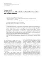
through another BS, which can provide a channel of sufficient signal strength (Figure 1.2).
A number of BSs are clustered together via a fixed-network connection to a mobile switching centre (MSC), which provides the switching functionality between BSs during handover
and can also provide connection to the fixed or core network (CN) to allow the routing of
calls. The clustering of BSs around a MSC is used to define a Location Area, which can be
used to determine the latest known location of a mobile user. This is achieved by associating
Home and Visitor Location Areas to a mobile. Each mobile is registered with a single home
location register (HLR) upon joining the network. Once a mobile roams outside of its Home
Location Area into a new designated Location Area, it temporarily registers with the network
as a visitor, where its details are stored in a visitor location register (VLR) associated with the
MSC. Each MSC in the network has an associated VLR and HLR. The mobile’s location is
relayed back to its HLR, a database containing various information on the mobile terminal,
some of which is then forwarded to the VLR. The network also comprises of other databases
Mobile Satellite Communication Networks
6
Figure 1.2
Basic cellular network architecture.
that can be used to verify that the mobile has access to the network, such as the Authentication
Centre (AuC), for example. These procedures are described later in the chapter for the GSM
system.
1.2.2 First-Generation (1G) Systems
1.2.2.1
Introduction
In the future mobile information society, where mobile-multimedia delivery will be the major
technological driving force, analogue cellular technology has little, if any significance.
Indeed, in many countries across Europe, mobile operators are now switching off their
analogue services in favour of digital technology. However, analogue technologies still
play an important role in many countries around the world, by being able to provide established and reliable mobile voice telephony at a competitive price. This section considers three
of the major analogue systems that can still be found with significant customer databases
throughout the world.
1.2.2.2
Nordic Mobile Telephone (NMT) System
On 1 October, 1981, the Nordic NMT450 became the first European cellular mobile communication system to be introduced into service [MAC-93]. This system was initially developed
to provide mobile communication facilities to the rural and less-populated regions of the
Scandinavian countries Denmark, Norway, Finland and Sweden. NMT450 was essentially
developed for in-car and portable telephones. By adopting common standards and operating
frequencies, roaming between Scandinavian countries was possible. Importantly, the intro-
Mobile Communication System Evolution
7
duction of this new technology provided network operators and suppliers with an early
market lead, one that has been sustained right up to the present day.
As is synonymous of 1G systems, NMT450 is an analogue system. It operates in the 450
MHz band, specifically 453–457.5 MHz (mobile to BS) and 463–467.5 MHz (BS to mobile).
FDMA/FM is employed as the multiple access scheme/modulation method for audio signals,
with a maximum frequency deviation of ^5 kHz. Frequency shift keying (FSK) is used to
modulate control signals with a frequency deviation of ^3.5 kHz. NMT450 operates using a
channel spacing of 25 kHz, enabling the support of 180 channels. Since its introduction, the
NMT450 system has continued to evolve with the development of the NMT450i (where
i stands for improvement) and NMT900 systems.
NMT900 was introduced into service in 1986, around about the same time as other Western
European countries were starting to introduce their own city based mobile cellular-based
solutions. NMT900 is designed for city use, catering for hand-held and portable terminals. It
operates in the 900 MHz band with the ability to accommodate higher data rates and more
channels.
The NMT system continues to hold a significant market share throughout the world and,
significantly, the system continues to evolve, through a series of planned upgrades. In Europe,
the NMT family has a particularly large market share in Eastern European countries, where
mobile telephony is only now starting to become prevalent.
The next phase in the evolution of the NMT450 network, as initiated by the NMT MoU, is
the digitisation of the standard. This is considered an important and necessary evolutionary
phase, in light of competition from existing 2G and future generation mobile networks. This
will be achieved through the down banding of the GSM network, and will be known as
GSM400. The possibility to provide dual-band GSM phones in order to support global
roaming is considered particularly attractive. Towards the end of 1999, Nokia and Ericsson
combined to demonstrate the first call made on a dual-mode GSM400/1800 prototype mobile
phone.
Since 1981, Nordic countries have continued to lead the way with now over 60% of the
population in Finland and Norway having a mobile phone. The Scandinavian-based companies Nokia and Ericsson are world leaders in mobile phone technology and both are driving
the phone’s evolution forward.
1.2.2.3
Advanced Mobile Phone Service (AMPS)
Bell Labs in the US developed the AMPS communications system in the late 1970s [BEL-79].
The AMPS system was introduced into commercial service in 1983 by AT&T with a 3-month
trial in Chicago. The system operates in the US in the 800 MHz band, specifically 824–849
MHz (mobile to BS) and 869–894 MHz (BS to mobile). These bands offer 832 channels, which
are divided equally between two operators in each geographical area. Of these 832 channels,
42 channels carry only system information. The AMPS system provides a channel spacing of
30 kHz using FM modulation with a 12 kHz peak frequency deviation for voice signals.
Signalling between mobile and BS is at 10 kbit/s employing Manchester coding. The
signals are modulated using FSK, with a frequency deviation of ^8 kHz. The AMPS system
specifies six one-way logical channels for transmission of user and signalling information.
The Reverse TCH and Forward TCH are dedicated to the transmission of user data on a oneto-one basis. Signalling information is carried to the BS on the channels reverse control
8
Mobile Satellite Communication Networks
channel (RECC) and reverse voice channel (RVC); and to the mobile using the channels
forward control channel (FOCC) and forward voice channel (FVC).
The forward and reverse control channels are used exclusively for network control information and can be referred to as Common Control Channels. To safeguard control channels
from the effect of the mobile channel, information is protected using concatenated pairs of
block codes. To further protect information, an inner code employs multiple repetition of
each BCH (Bose–Chadhuri–Hocquenghem) code word at least five times, and 11 times for
the FVC.
In order to identify the BS assigned to a call, AMPS employs a supervisory audio tone
(SAT), which can be one of three frequencies (5970, 6000 and 6030 Hz). At call set-up, a
mobile terminal is informed of the SAT at the BS to which it communicates. During a call, the
mobile terminal continuously monitors the SAT injected by the BS. The BS also monitors the
same SAT injected by the mobile terminal. Should the received SAT be incorrect at either the
mobile terminal or the BS, the signal is muted, since this would imply reception of a source of
interference.
Like NMT450, the AMPS standard has continued to evolve and remains one of the most
widely used systems in the world. Although market penetration did not reach Europe, at least
in its unmodified form, it remains a dominant standard in the Americas and Asia.
Narrowband-AMPS Motorola developed the narrowband-AMPS (N-AMPS) system in
order to increase the available capacity offered by the network. This was achieved by
dividing the available 30 kHz AMPS channel into three. N-AMPS employs frequency
modulation with a maximum deviation of 5 kHz from the carrier. From the outset, mobile
phones were developed for dual-mode operation allowing operation with the AMPS 30 kHz
channel.
Due to the narrower bandwidth, there is a slight degradation in speech quality when
compared to AMPS. In order to optimise reception, N-AMPS employs a radio resource
management technique called Mobile Reported Interference. This procedure involves the
mobile terminal monitoring the received signal strength of a forward narrow TCH and the
BER on the control signals of the associated control channel. A BS sends the mobile a
decision threshold on the reserve associated control channel, below which handover can be
initiated.
Signalling control channels are transmitted using a continuous 100 bit/s Manchester coded
in-band sub-audible signal. In addition to signalling messages, alphanumeric messages can
also be transmitted to the mobile.
N-AMPS was standardised in 1992 under IS-88, IS-89 and IS-90. In 1993, IS-88 was
combined with the AMPS standard IS-553 to form a single common analogue standard.
1.2.2.4
Total Access Communications System (TACS)
By the mid-1980s, most of Western Europe had mobile cellular capability, although each
country tended to adopt its own system. For example, the C-NETZ system was introduced in
Germany and Austria, and RADIOCOM 2000 and NMT-F, the French version of NMT900
could be found in France. This variety of technology made it impossible for international
commuters to use their phones on international networks, since every national operator had its
own standard. In the UK, Racal Vodafone and Cellnet, competing operators providing tech-
Mobile Communication System Evolution
9
nically compatible systems, introduced the TACS into service in January 1985. TACS was
based on the American AMPS standard with modifications to the operating frequencies and
channel spacing. TACS offers a capacity of 600 channels in the bands 890–905 MHz (mobile
to BS) and 935–950 MHz (BS to mobile), the available bandwidth being divided equally
between the two operators. Twenty-one of these channels are dedicated for control channels
per operator. The system was developed with the aim of serving highly populated urban areas
as well as rural areas. This necessitated the use of a small cell size in urban areas of 1 km. In
TACS, the cell size ranges from 1 to 10 km. TACS provides a channel spacing of 25 kHz
using FM modulation with a 9.5 kHz peak deviation for voice signals. In highly densely
populated regions, the number of available channels is increased to up to 640 (320 channels
per operator) by extending the available spectrum to below the conference of European Posts
and Telegraphs (CEPT) cellular band. This is known as extended TACS (ETACS). Here, the
operating frequency bands are 917–933 MHz in the mobile to BS direction and 872–888 MHz
in the BS to mobile.
Fifteen years after TACS was first introduced into the UK, the combined Vodafone and
Cellnet customer base amounted to just under half a million subscribers out of a total of 31
million. The future of analogue technology in developed markets is clearly limited, particularly with the re-farming of the spectrum for the 3G services. Nevertheless, analogue systems
such as TACS have been responsible for developing the mobile culture and in this respect,
their contribution to the evolution of the mobile society remains significant.
Within Europe, TACS networks can also be found in Austria, Azerbaijan, Ireland, Italy,
Malta and Spain. A variant of TACS, known as J-TACS, operates in Japan.
1.2.3 Second-Generation (2G) Systems
1.2.3.1
Global System for Mobile Communications (GSM)
Development Following a proposal by Nordic Telecom and Netherlands PTT, the Group
´
Special Mobil (GSM) study group was formed in 1982 by the CEPT. The aim of this study
group was to define a pan-European public land mobile system.
By the middle of the 1980s, the mobile industry’s attention had focused on the need to
implement more spectrally efficient 2G digital type services, offering a number of significant
advantages including greater immunity to interference, increased security and the possibility
of providing a wider range of services. Unlike the evolution of the North American AMPS,
which will be discussed shortly, the implementation of GSM took a more revolutionary
approach to its design and implementation.
In 1987, 13 operators and administrators signed the GSM memorandum of understanding
(MoU) agreement and the original French name was changed to the more descriptive Global
System for Mobile communications (GSM), although the acronym remained the same. By
1999, 296 operators and administrators from 110 countries had signed the GSM MoU.
Significantly, in 1987, following the evaluation of several candidate technologies through
laboratory and field trial experiments, agreement was reached on the use of a regular pulse
excitation-linear predictive coder (RPE-LPC) for speech coding and TDMA was selected as
the multiple access method.
In 1989 responsibility for the GSM specification was transferred to the ETSI and a
year later Phase 1 GSM specifications were published. Commercial GSM services began
Mobile Satellite Communication Networks
10
in Europe two years later in mid-1991. In addition to voice services, the SMS was
created as part of the GSM Phase 1 standard. This provides the facility to send and
receive text messages from mobile phones. Messages can be up to 160 characters in
length and can be used to alert the user of an incoming e-mail message, for example. It
is a store-and-forward service, with all messages passing through an SMS centre. The
SMS has proved to be hugely popular in Europe, with the transmission of in excess of 1
billion messages per month as of April 1999.
In 1997, Phase 2 specifications came on-line, allowing the transmission of fax and data
services.
At the end of 1998, ETSI completed its standardisation of GSM Phase 21 services high
speed circuit switched data (HSCSD) and general packet radio service (GPRS). These two
new services are aimed very much at exploiting the potential markets in the mobile data
sector, recognising the influence of the Internet on mobile technologies. HSCSD and GPRS
will be discussed shortly.
Responsibility for the maintenance and future development of the GSM standards is now
under the control of the 3G partnership project (3GPP).
Radio Interface The ITU allocated the bands 890–915 MHz for the uplink (mobile to BS)
and 935–960 MHz for the downlink (BS to mobile) for mobile networks. As has already been
seen, analogue mobile services were already using most of the available spectrum, however,
the upper 10 MHz in each band was initially reserved for the introduction of GSM operation,
with coexistence in the UK with TACS in the 935–950 and 890–905 bands.
The modulation method adopted by GSM is Gaussian-filtered minimum shift keying
(GMSK) with a BT (3 dB bandwidth £ bit period) value of 0.3 at a gross data rate of 270
kbit/s. This enables a compromise between complexity of the transmitter (which is important
when trying to maintain a low-cost terminal), increased spectral efficiency and limited spurious emissions (which is necessary to limit adjacent channel interference).
GSM specifies five categories of terminal class, as shown in Table 1.1. The power level can
be adjusted up or down in steps of 2 dB to a minimum of 13 dBm. The power control is
achieved by the mobile station (MS) measuring the signal strength or quality of the mobile
link, which is then passed to the base transceiver station (BTS). The BTS, in turn determines
if and when the power level should be adjusted. BTSs are categorised, in a similar manner,
into eight classes ranging from 2.5 to 320 W in 3-dB steps. In order to limit co-channel
interference, both the mobile and the BTS operate at the minimum power level required to
maintain signal quality.
Table 1.1
GSM terminal classes
Class
Peak transmit
power (W)
Peak transmit
power (dBm)
1
2
3
4
5
20
8
5
2
0.8
43
39
37
33
29
Mobile Communication System Evolution
11
GSM’s multiple access scheme is based on a TDMA/FDMA approach, combined with
optional slow frequency hopping, which can be used to counteract multipath fading and
co-channel interference [HOD-90]. Each band is divided into 124 carrier frequencies using
FDMA, and separated by 200 kHz. Each carrier frequency is divided in time, using a
TDMA scheme, into eight time-slots for full-rate operation (or 16 for half-rate). GSM
supports both full-rate and half-rate TCHs, referred to as TCH/F and TCH/H, respectively.
The full-rate channel supports a gross data rate of 22.8 kbit/s and allows data to be
transmitted at 12, 6 or 3 kbit/s. The half-rate channel, which occupies half a TDMA
slot, supports a gross data rate of 11.4 kbit/s. Data can be transmitted at 6 or 3.6 kbit/s.
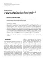
The full-rate TDMA frame structure is shown in Figure 1.3.
The GSM full-rate speech coder has an output rate of 13 kbit/s. Speech is handled in blocks
of 20 ms duration, hence the output of the speech coder will produce streams of 260 bits. Each
block of 260 bits is then subject to error correction. GSM divides speech bits into two classes:
‘‘Class 1’’ bits have a strong influence on perceived signal quality and are subject to error
correction; ‘‘Class 2’’ bits are left unprotected. Of the 260 bits in a 20-ms frame, 182 bits are
termed ‘‘Class 1’’. The Class 1 bits are further divided into 50 Class 1a bits, which are most
sensitive to bit errors, and Class 1b bits, which account for the other 132 bits. Three cyclic
redundancy code bits are added to the Class 1a bits, which are then added to the Class 1b bits,
before adding four tail bits resulting in 189 bits in total. These bits are then subject to half-rate
convolutional coding. This results in 378 bits being output from the encoder, which are then
added to the 78 unprotected bits, resulting in a total of 456 bits in a 20-ms frame, equivalent to
a coded rate of 22.8 kbit/s (Figure 1.4).
The output of the error correction device is fed into the channel coder, which performs
interleaving of the bits. Interleaving and associated de-interleaving at the receiver are used to
disperse the effect of bursty errors introduced by the mobile transmission environment. (This
technique is also employed in mobile-satellite communications (see Chapter 5).) The coder
Figure 1.3
GSM TDMA 26-frame structure.
Mobile Satellite Communication Networks
12
Figure 1.4
GSM full-rate speech coder.
takes two 20-ms time frames, equivalent to 912 bits, and arranges them into eight blocks of
114 bits. Each block of 114 bits is then placed in a time-slot for transmission.
Two 57-bit fields are allocated for the transmission of information within each GSM
time-slot. In addition to information content, each time-slot comprises three tail-bits (all
logical zeros) located at the beginning and the end of each time-slot. These bits are used to
provide a buffer between time-slots; two control bits, which follow each 57 bit of user
information, that are used to distinguish between voice and data transmissions; and a 26-bit
training sequence, located in the middle of the slot. The training sequence is used for
identification purposes and to perform channel equalisation. A guard-time of 30.5 ms,
corresponding to 8.25 bits, is then added to the time-slot prior to transmission [GOO-91].
Each time-slot lasts for 0.577 ms, during which time 156.25 bits are transmitted, resulting in
a gross bit rate of 270.833 kbit/s.
A group of eight time-slots is called a TDMA frame, which is of 4.615 ms duration. Each
time-slot is used to communicate with an individual mobile station, hence each TDMA frame
can support eight users at a time. TDMA frames are grouped into what is known as multiframes, consisting of either 26 or 51 TDMA frames. In the 26-frame format, 24 frames are
allocated to TCHs (TCH/F), with each TCH occupying one of the eight timeslots per frame,
and one frame (frame-12) for the eight associated slow associated control channels (SACCH).
The other frame (frame-25) remains spare unless half-rate operation is employed, in which
case it is occupied by the eight other SACCHs associated with the extra TCHs. An SACCH is
used for control and supervisory signals associated with a TCH. In addition, a fast associated
control channel (FACCH) steals slots from a TCH in order to transmit power control and
handover signalling messages.
GSM employs a number of logical control channels to manage its network. These channels
are grouped under three categories: broadcast control channel (BCCH); common control
channel (CCCH); and dedicated control channel (DCCH). The GSM logical control channels
are summarised in Table 1.2. With the exception of the SACCH and FACCH, which are
transmitted on the 26-frame structure, these channels are transmitted using the 51-frame
structure.
Fifty-one of the 26-frame and 26 of the 51-frame formats are combined to form a GSM
superframe, and the TDMA hierarchy is complete when 2048 superframes are combined to
form a hyperframe [WAL-99].
Mobile Communication System Evolution
Table 1.2
13
GSM logical control channels
Group
Channel
Description
DCCH
Slow associated control
channel (SACCH)
Fast associated control
channel (FACCH)
Control and supervisory signals associated with the TCH
DCCH
DCCH
BCCH
BCCH
BCCH
CCCH
CCCH
CCCH
Stand-alone dedicated
control channel (SDCCH)
Frequency correction
channel (FCCH) – downlink
Synchronisation channel
(SCH)
Broadcast control channel
(BCCH) – downlink only
Paging channel (PCH) –
downlink only
Random access channel
(RACH) – uplink only
Access grant channel
(AGCH) – downlink only
Steals timeslots from the traffic allocation and used for
control requirements, such as handover and power
control
Used for registration, location updating, and
authentication and call set-up
Allows mobiles to achieve initial frequency
synchronisation with the local BTS
Allows mobiles to achieve initial time synchronisation
with the local BTS
Provides the MS with information such as BS identity,
frequency allocation and frequency hopping sequences
Alerts the mobile that the network requires to signal it
A slotted-ALOHA channel used by the MS to request
access to the network
Used to allocate a stand-alone DCCH to a mobile for
signalling, following a request on the RACCH
Network Architecture A simplified form of the GSM network architecture is shown in
Figure 1.5.
Mobile Station (MS) A subscriber uses an MS to access services provided by the
network. The MS consists of two entities, the mobile equipment (ME) and subscriber
identity module (SIM). The ME performs the functions required to support the radio
Figure 1.5
GSM simplified network architecture.
14
Mobile Satellite Communication Networks
channel between the MS and a BTS. These functions include modulation, coding, and so
on. It also provides the application interface of the MS to enable the user to access
services. A SIM card provides the ability to personalise a mobile phone. This is a
smart card that needs to be inserted into the mobile phone before it can become
operational. The SIM card contains the user’s international mobile subscriber identity
(IMSI), as well as other user specific data including an authentication key. Similarly, a
terminal is identified by its international ME identity (IMEI). The IMSI and IMEI provide
the capability for personal and terminal mobility, respectively. The radio interface between
the MT and the BTS is termed the Um-interface and is one of the two mandatory
interfaces in the GSM network.
Base Station System (BSS) The BTS forms part of the base station system (BSS), along
with the base station controller (BSC). The BTS provides the radio coverage per cell, while
the BSC performs the necessary control functions, which include channel allocation and local
switching to achieve handover when a mobile moves from one BTS to another under the
control of the same BSC. A BTS is connected to a BSC via an Abis-interface.
Network Management and Switching Subsystem (NMSS) The NMSS provides the
connection between the mobile user and other users. Central to the operation of the NMSS
is the MSC. A BSS is connected to an MSC via an A-interface, the other mandatory GSM
interface. The coverage area of an MSC is determined by the cellular coverage provided by
the BTSs that are connected to it. The functions of an MSC include the routing of calls to the
appropriate BSS, performing handover between BSSs and inter-working with other fixed
networks. A special type of MSC is the gateway MSC (GMSC), which provides
connection to fixed telephone networks and vice versa. A GMSC is connected to an MSC
via an E-interface. Central to the operation of the MSC are the two databases: HLR,
connected via the C-interface; and VLR, connected via the B-interface.
The HLR database contains management information for an MS. Each MS has an associated HLR. The information contained within an HLR includes the present location of an
MS, and its IMSI, which is used by the authentication centre (AuC) to authorise a subscriber’s
access to the network. A service profile is stored on the HLR for each MS, as is the last known
VLR and any subscriber restrictions.
Each MSC has an associated VLR. Whenever an MS is switched on in a new location area
or roams into a new location area covered by an MSC, it must register with its VLR. At this
stage, the visiting network assigns a MS roaming number (MSRN) and a temporary mobile
subscriber identity (TIMSI) to the MS. The location of the MS, usually in terms of the VLR’s
signalling address, is then conveyed to the HLR. The VLR, by using subscriber information
provided by the HLR, can perform the necessary routing, verification and authentication
procedures for an MS that would normally be performed by the HLR.
An MSC also provides connection to the SMS centre (SMSC), which is responsible for
storing and forwarding messages.
Operation Subsystem (OSS) The OSS provides the functions for the operation and
management of the network. The Network Operation and Maintenance Centre performs all
the necessary functionalities necessary to monitor and manage the network. It is connected to
all of the major network elements (BTS, MSC, HLR, VLR) via an O-interface using an X.25
connection. The equipment interface register (EIR) is used by the network to identify any
equipment that may be using the network illegally. The MSC-EIR connection is specified by
the F-interface. The AuC also forms part of the OSS.
Mobile Communication System Evolution
15
Mobility related and other GSM signalling in the CN is performed by the mobile application part (MAP), developed specifically for GSM. Importantly, the GSM MAP will be used to
provide one of the CNs for IMT-2000.
1.2.3.2
Digital Cellular System 1800 (DCS1800)
The first evolution of GSM came about with the introduction of DCS1800, which is aimed
primarily at the mass-market pedestrian user located in urban, densely populated regions.
DCS1800 was introduced under the personal communications network (PCN) concept, also
known as personal communication services (PCS) in the US. In 1989, the UK Government’s
Department of Trade and Industry outlined its intention to issue licenses for personal communication networks in the 1700–2300 MHz band [DTI-89]. It was recognised that the new
service, which would be aimed primarily at the pedestrian user, would be an adaptation of the
GSM standard. Subsequently, ETSI produced the Phase 1 DCS1800 specification in January
1991, which detailed the generic differences between DCS1800 and GSM. This was followed
by a Phase 2 specification detailing a common framework for PCN and GSM. DCS1800
operates using largely the same specification as GSM, making use of the same network
architecture but, as its name implies, it operates in the 1800 MHz band. Here, parallels can
be drawn with the evolution of the NMT450 to the NMT900 system from earlier discussions.
The bands that have been allocated for DCS1800 operation are 1710–1785 MHz for the
mobile to BS link and 1805–1880 MHz for the BS to mobile link. Taking into account the
200-kHz guard-band, 374 carriers can be supported. Apart from the difference in the operating frequency, the only other major difference is in the transmit power specification of the
mobile station. Two power classes were defined at 250 mW and 1 W peak power, respectively. As DCS1800 is intended primarily for urban environments, the cells are much smaller
than those of GSM; hence the transmit power requirements are reduced.
The UK was the first country to introduce PCN into operation, through two network
operators: Mercury’s One2One, which was introduced into service in September 1993; and
Hutchinson’s Orange, which was introduced into service in April 1994.
Dual-mode 900/1800 MHz terminals are now available on the market, as are triple-mode
900/1800/1900 MHz terminals, allowing roaming into North America (in the US, the 1900
MHz band is used for PCS). Towards the end of 1999, Orange and One2One accounted for a
third of the UK digital cellular market at just under 5 million subscribers, with virtually an
equal market share between the two of them [MCI-99].
1.2.3.3
Digital Advanced Mobile Phone Services (D-AMPS)
D-AMPS was specified by the Telecommunications Industry Association (TIA) Interim
Standard-54 (IS-54) in 1990, as an intermediate solution while a fully digital standard was
specified. IS-54 retained the analogue AMPS control channels and gave operators the opportunity to provide digital cellular services while the complete digital standard was being
developed. A fully digital standard was specified as IS-136, which uses the same digital
radio channels as IS-54, and also includes digital signalling channels. Mobility related and
other signalling in the CN is specified by the IS-41 standard. Importantly, as with the GSM
MAP, IS-41 will be used to provide one of the CNs for IMT-2000.
Mobile Satellite Communication Networks
16
Due to regulatory constraints, D-AMPS operates alongside AMPS in the same frequency
bands in the US. As with the European digital system, GSM, the multiple access technique is
based on TDMA, however, a reduced hierarchical approach to the frame structure is implemented, resulting in a simpler implementation. As with AMPS, the carrier spacing is 30 kHz.
D-AMPS employs Pi/4-shifted DPSK as the modulation method. Carriers are transmitted at
48.6 kbit/s and root raised cosine filtering with a roll-off factor of 0.35 is employed at the
transmitter and receiver.
A TDMA frame consists of six time-slots, each of 6.67 ms duration; a frame is of 40 ms
duration. Each slot contains 324 bits including 260 bits of user information. In the mobile to
BS direction, these information bits are divided into three packets of 16, 122 and 122 bits,
respectively. In the opposite direction, data are divided equally into two 130-bit packets. In
addition to user information, the mobile to BS time-slot contains [GOO-91]:
† Six guard bits, six ramp time bits and 28 bits of synchronisation information containing a
known bit pattern, one for each time-slot in a frame.
† A 12-bit digital verification colour code, to assist with the management of time-slot
assignments.
† And 12 bits of system control information, transmitted on the slow access control channel
(SACCH).
In the BS to mobile direction, the capacity allocated to the guard and ramp time bits is
reserved for future use. The structure of the slots is shown in Figure 1.6.
D-AMPS adopts vector sum excited linear prediction (VSELP) as the speech coding
technique. The output from the coder produces a source rate of 7.95 kb/s, which is then
subject to coding. Output bits are processed in 20-ms bursts, or in other words blocks of 159
bits. Of these 159 bits, 77 are termed class 1 bits, which are considered to have the greater
influence on speech quality, using a similar approach to GSM. These 77 bits are subject to an
error detecting code, in the form of the addition of seven parity checks and five tail bits, and
half-rate convolutional coding. The resultant 178 bits are then multiplexed with the other 82
Figure 1.6
D-AMPS time-slot structure.
Mobile Communication System Evolution
17
bits to produce 260 bits. These blocks of 260 bits are then interleaved in order to protect the
information from bursty errors caused by the mobile channel, and then placed in the assigned
slots in the TDMA frame.
D-AMPS has been developed as a dual-mode system, providing in effect backward
compatibility with its analogue counterpart. As far as control signals are concerned, DAMPS uses the SACCH and the FACCH to communicate with the network. Control
messages have a length of 65 bits. For the FACCH, where immediate control information
needs to be transmitted, 1/4-rate convolutional coding is applied, resulting in 260 bits,
which are then inserted into a single time-slot. For the SACCH, half-rate convolutional
coding is applied and the resultant bits are dispersed over 12 time-slots, resulting in a
delay of 240 ms.
1.2.3.4
cmdaOne
In 1991, Qualcomm announced the development of a CDMA based mobile system. This
was subsequently specified as Interim Standard-95A (IS-95A) and later became known
under the commercial name cmdaOne, as established by the CDMA Development Group
(CDG). Interestingly, one of Qualcomm’s main products is OMNITRACS, a geostationary
satellite based fleet management system incorporating two-way mobile communications
and position reporting services. Qualcomm is also a partner in the GLOBALSTAR
project, a non-geostationary satellite system, which will be discussed in the following
chapter. GLOBALSTAR incorporates a modified version of the cmdaOne radio access
technique. In 1995, Hutchinson became the first operator to launch cmdaOne in Hong
Kong.
Like D-AMPS, cmdaOne is a dual-mode system, which operates alongside the AMPS
service in the same band. Digital transmissions are used by default and the mobile automatically switches to analogue mode when no digital coverage is available. Mobility
related and other signalling in the CN is specified by the IS-41 standard. The mobile
transmits at 45 MHz below the BS transmit frequency and channels are separated by 30
kHz. Specifically, the operational frequency bands are 869–894 MHz (BS to mobile) and
824–849 MHz (mobile to BS). cmdaOne also operates in the PCS band (1930–1980 MHz
uplink, 1850–1910 MHz downlink) and dual-band phones are available. It can be seen that
in the PCS band, the mobile transmits at 80 MHz below the BS, moreover, channels are
separated by 50 kHz. The system operates using a bandwidth of 1.23 MHz, this being
equivalent to 41 different 30-kHz AMPS channels. One of the advantages of CDMA is the
increase in available capacity when compared to other cellular technologies. In this respect
a more than ten-fold capacity increase when compared to AMPS, and a three-fold increase
when compared to a TDMA system is possible.
Unlike other cellular systems, the Qualcomm CDMA system operates using different
transmission techniques on the forward and reverse directions.
In the IS-95A forward direction, each BS has access to 64 CDMA channels. These channels are categorised as either common control channels, which are broadcast to all mobile
terminals, or broadcast channels, which are dedicated to a particular terminal. Each channel is
derived from one row of a 64 £ 64 Walsh Hadamard matrix, with the row numbers transcending from 0 to 63. One of the common control channels, Walsh function 0, which comprises all
zeros, is used to transmit the pilot signal. Another of the common control channels, Channel
18
Mobile Satellite Communication Networks
32, acts as a synchronisation (SYNC) channel, providing mobile terminals with important
system information such as the BS identifier, the time-offset specific to the BS introduced in
the radio modulator and system time. BSs are synchronised using the Global Positioning
System (GPS) satellite system [GET-93]. The SYNC channel always transmits at a data rate
of 1200 bit/s.
The remaining 62 channels are available for traffic over a broadcast channel, with up to
the first seven of these being available for paging, using a common control channel. The
paging channel operates at either 4.8 or 9.6 kbit/s and is used to alert the mobile of an
incoming call.
Variable rate voice coding produces data rates in the range 1.2–9.6 kbit/s for Rate Set 1,
or 1.8–14.4 kbit/s for Rate Set 2, depending on speech activity. Rate Set 2 is optional on
the forward TCH and is only available in the PCS band, which also supports Rate Set 1.
Data are grouped into 20-ms frames. This is then encoded using a half-rate convolutional
encoder with a constraint length of 9 for Rate Set 1. Rate Set 2 differs only in that it
employs a 3/4-rate convolutional encoder of constraint length nine. In order to ensure a
constant rate of 19.2 kbit/s, repetition of lower rate code bits is performed prior to
interleaving and spreading by a pseudo-random sequence derived from the long code,
which repeats itself after 2 4221 chips, and a long code mask, which is unique to each
terminal and contains the mobile’s electronic serial number. This 19.2-kbit/s signal is then
multiplexed with power control bits, which are applied at 800 bit/s. The Walsh code
assigned to the user’s TCH is then used to spread the signal. Quadrature phase shift
keying (QPSK) is used to modulate the carrier, introducing a time-offset associated with
the BS to the in-phase and quadrature components. This delay is introduced since BSs
with different time offsets appear as background noise to the mobile, hence reducing
interference levels. A quadrature pair of pseudo-noise (PN) sequences is then used to
spread the signal at 1.2288 Mchip/s. Baseband filtering is then applied to ensure that
the components of the modulation remain within the channel before modulating the inphase and quadrature signals onto the CDMA channel. BSs vary radiated power in proportion to data rate in a frame. So, for example, a 1.2-kbit/s signal would be transmitted at an
eighth of the power of a 9.6-kbit/s signal. This ensures that all bits are transmitted with the
same energy [GAR-96] (Figure 1.7).
The reverse direction has two associated channels: the access channel and the TCH. The
access channel is used by the mobile to request a TCH, respond to a paging message, or for
location updates. This operates at 4.8 kbit/s. An access channel is associated with a particular
paging channel, and from the above discussion on the forward link, it can be seen that up to
seven access channels can exist.
As before, the TCH supports Rate Set 1 and may support Rate Set 2. In the reverse
direction, variable rate voice coding produces data rates in the range 1.2–9.6 kbit/s for Rate
Set 1, or 1.8–14.4 kbit/s for Rate Set 2, depending on speech activity. So, for example, a
data rate of 1.2 kbit/s corresponds to the transmission of no speech. Data are organised into
20-ms frames. For Rate Set 1, this is then encoded using a 1/3-rate convolutional encoder
with a constraint length of 9. As in the forward direction, in order to ensure a constant rate
of 28.8 kbit/s, repetition of lower rate code bits is performed. Rate Set 2 employs a half-rate
convolutional encoder of constraint length 9, again employing repetition to ensure a
constant rate of 28.8 kbit/s. The encoded bits are then interleaved prior to Orthogonal
Walsh modulation, by which a block of six code symbols is used to generate a sequence
Mobile Communication System Evolution
Figure 1.7
19
cmdaOne forward traffic modulation.
of 64 bits, corresponding to a row of a 64 £ 64 Walsh Hadamard matrix. Each mobile
transmits a different Walsh code, enabling the BS to identify the transmitter. A data burst
randomiser is then applied with a duty cycle inversely proportional to the data rate. This
results in the random distribution of energy over each frame, independent of other potential
interfering terminals operating in the same cell. This is different from the technique
described above for the BSs. The long code, which repeats itself after 2 42 21 chips, and
long code mask, which is unique to each terminal and contains the mobile’s electronic serial
number, are then used to spread the signal at 1.2288 Mchip/s. Offset-QPSK is used to
modulate the carrier. This involves delaying the quadrature channel by half a chip. The
same quadrature pair of PN sequences, as used by the BS, is then used to spread the signal
at 1.2288 Mchip/s with a periodicity of 2 15 21 chips. Baseband filtering is then applied to
ensure that the components of the modulation remain within the channel before modulating
the in-phase and quadrature signals onto the CDMA channel (Figure 1.8).
In September 1998, Leap Wireless International Inc., an independent Qualcomm spin-off
company was formed, its purpose being to deploy CDMA based networks. As well as North
America, cmdaOne is deployed throughout the world including the major markets of Australia, China, South Korea and Japan; and as of 1999, there were 43 wireless local loop (WLL)
systems in 22 countries using cmdaOne technology. The co-existence of cmdaOne and GSM
networks in Australia and China, the latter a potentially huge market, has led to the possibility
of the development of a dual GSM/cmdaOne handset.
cmdaOne is now only second to GSM in the world market stakes. This is despite the fact
that no significant market penetration has been achieved in Europe. The proponents of
Mobile Satellite Communication Networks
20
Figure 1.8 cmdaOne reverse traffic modulation.
cmdaOne see it as an important stepping stone towards the development of 3G networks.
Indeed, the evolution of cmdaOne, known as multicarrier CDMA, was selected as one of the
family of radio interfaces for IMT-2000.
1.2.3.5
Personal Digital Cellular System (PDC)
The air interface of the PDC, formerly known as the Japanese digital cellular system (JDC),
was specified in April 1991, following 2 years of investigation. PDC operates in two
frequency bands: 800 MHz with 130 MHz duplex operation; and 1.5 GHz with 48 MHz
duplex operation. The bands are divided into 25-kHz channels. Nippon Telegraph and Telephone (NTT) introduced PDC into service in 1993 at the lower of the two aforementioned
frequency bands, before adding the higher band operation in 1994.
The multiple access scheme employed is three- or six-channel TDMA/frequency division
duplex (FDD), depending on whether a full or half-rate codec is employed. A TDMA frame is
of 20 ms duration, which is divided into six slots. The information bit rate is at 11.2 kbit/s at
full-rate or 5.6 kbit/s at half-rate. The modulation method used is Pi/4-differential (D)QPSK,
which is transmitted at a bit rate of 42 kbit/s.
Mobile Communication System Evolution
21
1.2.4 Evolved Second-Generation (2G) Systems
1.2.4.1
Overview
So-called evolved 2G networks are aimed at exploiting the demand for mobile data
services, with the emphasis being on the availability of higher data rates in comparison
to 2G services. The majority of these service offerings also point the way towards
packet-oriented delivery.
1.2.4.2
High Speed Circuit Switched Data (HSCSD)
In recognition of the needs of the market, the HSCSD service is aimed very much at the
mobile user who needs to access or to transmit large data files while on the move. Transmission of large files, of the order of megabytes, is clearly unattractive when using the GSM rate
of 9.6 kbit/s. However, by making available up to eight GSM full-rate TCHs to a single user,
HSCSD can achieve rates of at least 76.8 kbit/s and if overhead reduction techniques are
employed, significantly higher data rates of 115 kbit/s and higher could be achievable.
Clearly such data rates will only be viable through network operators with a large amount
of spare capacity that are willing to address niche market applications.
The HSCSD makes use of the GSM network architecture and no modifications to the
physical infrastructure of the network are required, only software upgrades. This is clearly
an attractive opportunity for network operators, by recognising the potential to create new,
potentially lucrative markets for a minimum investment. However, the long-term future of
HSCSD is unclear as the future of data transmission appears to be based on packet-switched
technology.
1.2.4.3
General Packet Radio Service (GPRS)
The introduction of the GPRS represents an important step in the evolution of the GSM
network. Significantly, GPRS is a packet-switched system, unlike GSM and HSCSD, which
are circuit-switched. The aim of GPRS is to provide Internet-type services to the mobile user,
bringing closer the convergence of IP and mobility. Indeed, apart from addressing a significant market in its own right, clearly GPRS can be considered to be an important stepping
stone between GSM and UMTS.
In packet-switched networks the user is continuously connected but may only be
charged for the data that is transported over the network. This is quite different from
circuit-switched networks, such as GSM, where a connection is established at call set-up
and the user is billed for the duration of the call, irrespective of whether any information
is transported. In this respect, packet-switched technology can be considered to be more
spectrally efficient and economically attractive. Essentially, channel resources are made
available to all users of the network. A user’s information is divided into packets and
transmitted when required. Other users are also able to access the channels when necessary.
A GPRS MS comprises mobile terminal (MT), which provides the mechanism for transmitting and receiving data and terminal equipment (TE), a PC-like device upon which
applications run. Within a GSM/GPRS network, a GPRS MS has the capability to function
in three operational modes, as shown in Table 1.3.
Mobile Satellite Communication Networks
22
Table 1.3
GPRS MS operational modes
Class
Operation
A
B
C
Simultaneous packet and circuit-switched modes
Automatic selection of circuit or packet-switched mode
Packet mode only
GPRS offers non-real time services at data rates from 9 up to 171 kbit/s, with most
networks offering about half the maximum data rate. The available bit rate is dependent
upon the number of users of the network and the type of channel coding employed. GPRS
specifies four types of coding (CS-1, CS-2, CS-3 and CS-4), the choice of which depends
on the operating environment. The theoretical maximum data rate is achieved by employing CS-4, whereby no coding is employed, and only a single user is gaining access to
channel resources. The data rates offered allow a full range of services to be accessed, from
simple messaging to efficient file transfer and web browsing. Inter-working with TCP/IP
and X.25 bearer services will be available. Once connected to the network, a call can be
established in less than 1 s, which is significantly faster than GSM. GPRS, in addition to
providing point-to-point services, has the capability to deliver point-to-multipoint calls,
where the receiving parties can be either closed-group or users within a particular broadcast
area.
GPRS makes use of the same radio interface as GSM. To achieve a variable data rate, a MS
can be allocated from one to eight time-slots within a particular TDMA frame. Moreover, the
time-slot allocation can be different in the forward and reverse directions. Hence, the MS can
transmit and receive data at different rates, thus enabling asymmetric service delivery. This
approach is the key to the efficient provision of Internet-type services. Channels are dynamically allocated to MSs on a per-demand basis from a common pool of resources available
to the network. Upon completing a communication, the channels are released by the MS and
returned to the pool, thus enabling multi-users to share the same channel resources. Packets
are transmitted on unidirectional packet data TCHs (PDTCH), which are similar to the fullrate TCHs used by GSM for speech. These channels are temporarily allocated to a particular
MS when data transfer occurs. TCHs are transmitted over a 52-multiframe physical channel,
which is made up of two GSM 26 multiframes. A 52-multiframe comprises of 12 blocks of
four TDMA frames plus two frames for the packet broadcast control channel (PBCCH) and
two spare. Hence, a 52-multiframe lasts for 240 ms. A 51-multiframe is also defined for the
exclusive transmission of the packet call control channel (PCCCH) and PBCCHs. In addition,
GPRS provides a number of logical channels for control and signalling purposes, grouped
under PBCCCH, packet dedicated control channel (PDCCH) and PCCCH. These are
summarised in Table 1.4.
The network architecture is based on GSM with some additions. The architecture consists
of the following components: Servicing GPRS (CHECK) support node; gateway GPRS
support node; MSC/VLR; HLR; BSS with packet control unit (PCU) – the PCU is a new
functional entity introduced by ETSI to support introduction of GPRS in GSM networks;
GPRS MS; and a GPRS IP backbone. The GPRS network architecture is shown in Figure 1.9.
The servicing GPRS support node (SGSN) is used to perform location monitoring of
individual mobile terminals, security functions and access control. An SGSN is connected
Mobile Communication System Evolution
23
Table 1.4
GPRS logical control channels
Group
Channel
Description
PDCCH
Packet associated control
channel (PACCH)
PDCCH
Packet timing advance control –
uplink direction (PTCCH/U)
Packet timing advance control –
downlink direction (PTCCH/D)
Packet broadcast control channel
(PBCCH) – downlink only
Packet notification channel
(PNC)
Packet paging channel (PPCH) –
downlink only
Packet random access channel
(PRACH) – uplink only
Packet access grant channel
(PAGCH) – downlink only
Provides signal information related to a specific
MS. Can be used for paging for circuit-switched
services, when MS is in packet-switched mode
Used by MS to transmit random access burst, from
which BS estimates timing advance
Used by BS to transmit timing advance
information to MSs
Used by the BS to provide the MS with specific
system information relating to packet data
Used to send a point-to-multipoint multicast
(PTM-M) to a group of MSs
Alerts the mobile prior to packet transfer
PDCCH
PBCCH
PCCCH
PCCCH
PCCCH
PCCCH
Used by the MS to initiate data transfer or
signalling
Used to assign resources to the MS prior to packet
transfer
to a BSS by G.703/G.704 frame relay. This is termed the Gb-interface. When a session needs
to be established, the SGSN establishes a ‘‘tunnel’’ between the mobile and a given packet
data network using the packet data protocol (PDP). This protocol provides the routing information and QoS profile required to transfer protocol data units between the MS and the
gateway GSN (GGSN). To provide closer co-ordination with GSM, a Gs-interface connecting the SGSN with an MSC is specified.
Figure 1.9
GPRS network architecture.
24
Mobile Satellite Communication Networks
The GGSN performs the functions necessary to allow inter-working with external packetswitched networks. Each external packet-switched network is referenced by a unique access
point name (APN). GGSNs are connected to SGSNs via an IP-based GPRS backbone
network. This is termed a Gn connection. The GGSN uses a GPRS tunnelling protocol
(GTP) to encapsulate IP packets received from external IP networks and to tunnel to the
SGSN. The connection between a GGSN and an IP network is termed Gi. An optional Gcinterface between the GGSN and the HLR is also specified, again to facilitate closer cooperation with the GSM network.
In addition to the new hardware elements introduced by GPRS, some software upgrades
are also necessary to the components of the GSM network elements, specifically the HLR
with GPRS subscriber information and optionally the MSC/VLR for more efficient co-ordination of services, for example, between GSM and GPRS subscribers.
An MS must perform a GPRS attach procedure before it can gain access to the services
provided by the network. This involves registering the MS with the local SGSN. Once
authorisation to use the services of the network has been verified and the user profile has
been obtained from the HLR, the SGSN supplies the MS with a packet temporary mobile
subscriber identity (P-TMSI).
Once an attach procedure has been performed, in order to be able to send and receive
packets, the MS must create a PDP context. This is used to describe the service characteristics
and comprises the following: a PDP address, which is an IP address allocated by the PDN to
which correspondence will take place; the PDP type (e.g. IPv6); the address of the GGSN
serving the PDN; and the required QoS. The PDP context is stored at the MS, SGSN and
GGSN and communication can then take place with the PDN. A user is not limited to a single
PDP context at any particular time. PDP addresses can be statically or dynamically allocated
to an MS. In the latter case, the GGSN is responsible for allocation/de-allocation, while in the
former, the user’s home network permanently assigns the PDP address.
A key feature of GPRS is its ability to support various categories of QoS, which, as noted
above, can be set for each PDP context. A QoS profile is derived from four criteria, service
precedence; delay; reliability; and throughput [BET-99]. Such a process allows the flexible
negotiation of required QoS based on the status of the network at the time of the session.
IS-136 and GPRS Cellular digital packet data (CDPD) was developed to provide packet
data services as a network overlay to the AMPS network [SAL-99]. Subsequently, this was
adapted to also provide solutions for the IS-136 and IS-95 networks. CDPD provides mobility
management features that are independent of those provided by IS-41. Consequently, a
mobile terminal would need to perform procedures associated with both networks. This is
unlike GPRS, which derives its mobility management features from the GSM MAP. As we
will see shortly, in the future mobile environment, the CN will comprise of IS-41 and GSM
MAP, which will be developed to allow network to network interworking. With this in mind,
it has been decided that a more elegant solution to the requirements for the evolution of the
IS-136 network towards a packet-oriented environment can be achieved by adapting the
GPRS network to the IS-41 standard [FAC-99]. Moreover, the adoption of the GPRS
network architecture offers two other major advantages: the world-wide availability of the
GSM network facilitates global roaming; and the 3G standard UWC-136, which is an
evolution of IS-136, makes use of the enhanced data rates for GSM evolution (EDGE)
radio interface.
Mobile Communication System Evolution
1.2.4.4
25
Enhanced Data Rates for GSM Evolution (EDGE)
The introduction of EDGE technology will further increase the network capacity and available data rates of both circuit-switched (HSCSD) and packet-switched (GPRS) GSM derivatives. This is achieved by the implementation of a new radio interface incorporating
8-phase shift keying (8-PSK), which will co-exist with the existing GSM modulation technique, GMSK. This new method of modulation enables available HSCSD and GPRS data
rates to be extended by up to three-fold per channel. Alternatively, existing data rates can be
achieved by using fewer time-slots, hence increasing network efficiency.
Importantly, no further modifications to the underlying GSM network are required. The
only updates are through software upgrades to take into account the new radio interface
technology. New multimedia-type terminals will also be introduced into the market in
order to exploit the new service capabilities offered by the network.
The Phase 1 EDGE standard, specified by ETSI, considers both enhanced HSCSD (ECSD)
and enhanced GPRS (EGPRS) services, with data rates of up to 38.4 kbit/s/time-slot and
60 kbit/s/time-slot, respectively. Higher data rates can be achieved by combining TCHs, so
for example, a 64-kbit/s service could be achieved by combining two ECSD channels. Rates
of over 400 kbit/s can be achieved for EGPRS.
Clearly at the rates offered, the boundary between EDGE and UMTS (to be discussed
shortly) becomes less and less distinct. EDGE will be able to provide the vast majority of
services envisaged by UMTS and an early market lead will be gained. EDGE and UMTS are
envisaged to operate alongside each other, particularly in the early years of UMTS deployment. Significantly, EDGE is also seen as a means for GSM operators without a UMTS
licence to supply personal multimedia services using existing GSM band allocations.
In fact, the division between GSM’s EDGE and 3G technologies is even less distinct, as
EDGE forms the basis of the UWC-136 solution that will provide the TDMA component of
the IMT-2000 family of radio systems.
1.2.4.5
IS-95B
IS-95B, the packet-mode version of IS-95A, is capable of delivering data rates of up to
115.2 kbit/s. This is achieved by combining up to a maximum of eight TCHs. A TCH
comprises a fundamental code channel (FCC) and between 0 and seven supplemental code
channels (SCC). The transmission rate of the FCC can vary in line with the Rate Sets 1 and 2
discussed previously (see section on IS-95A), where as the SCC channels operate at the
maximum bit rates associated with the particular Rate Set (9.6 or 14.4 kbit/s). The transmission of the signals is as described for IS-95A.
The IS-95B standard forms the basis for the 3G cdma2000 solution, which is one of the
family of radio interfaces selected for IMT-2000.
1.2.4.6
I-Mode
In February 1999, NTT DoCoMo launched its proprietary commercial mobile Internet
service, i-mode. Within two years, the service had attracted just under 20 million subscribers,
well in excess of original market expectations. The i-mode network is essentially a PDC
overlay, providing packet data rates at 9.6 kbit/s up to a maximum of 28.8 kbit/s. In this