Integrated Terrestrial-Satellite Mobile Networks
Bạn đang xem bản rút gọn của tài liệu. Xem và tải ngay bản đầy đủ của tài liệu tại đây (525.43 KB, 46 trang )
7
Integrated Terrestrial-Satellite
Mobile Networks
7.1 Introduction
Satellite integration into terrestrial mobile networks may take two paths: the evolutionary or
the revolutionary approach. In the evolutionary scenario, existing standards are gradually
evolved towards a new technical standard. In contrast, the revolutionary policy necessitates a
completely new approach to the problem, disregarding existing standards and consequently
new standards will emerge. At the start of the last decade, it was not clear which path the
future development of mobile communications would take. However, by the end of the
decade, it became clear that any new system would have to take into account the investments
made by industry and the technological developments that had taken place. Moreover, the
level of market take-up requires the need to ensure that there is some form of backward
compatibility with existing systems.
We have already seen how GSM is evolving towards GPRS and EDGE, while cdmaOne is
following a similar path towards cdma2000. With this in mind, it is clear that there would be
very little support for introducing a revolutionary new system at this stage of the mobile
communications development. It could be argued that W-CDMA is indeed a revolutionary
new system, however, it is important to realise that the underpinning core network technology
is still that of GSM. However, with the introduction of an all-IP core network, certainly the
move from circuit to packet-oriented delivery can be considered to be a significant change in
the mode of delivery.
As far as satellites are concerned, the future requirement to inter-work seamlessly with
terrestrial mobile networks is paramount. Hence, there is a need to be able to adapt the
terrestrial mobile standards to those of the space segment. With this in mind, this chapter
will concentrate on the evolutionary approach and in particular, issues in relation to satellite-
personal communication network (S-PCN) integration with the fixed public switched tele-
phone network (PSTN), GSM and GPRS will be discussed.
In order to determine the level of integration between the S-PCN and different terrestrial
networks, the requirements imposed by the mobile users, the service providers and the
network operators have to be identified. Such requirements will enable the identification of
Mobile Satellite Communication Networks. Ray E. Sheriff and Y. Fun Hu
Copyright q 2001 John Wiley & Sons Ltd
ISBNs: 0-471-72047-X (Hardback); 0-470-845562 (Electronic)
the required modifications or adaptation of terrestrial mobile network functions for the
support of interworking between space and terrestrial networks.
This chapter is partly based on the work carried out in the EU RACE II SAINT project,
which paved the way for satellite-UMTS studies in Europe and ETSI’s GMR specifications,
which define the requirements for integration between a geostationary satellite and the GSM
network.
7.2 Integration with PSTN
7.2.1 Introduction
Mobile satellite networks are required to interwork with both fixed and mobile networks,
including PSTN and GSM. Due to different national PSTN implementation standards, inter-
operability between PSTN and S-PCN relies on the use of ITU-T Signalling System No. 7
(SSN7) both within national networks and at the international interconnection point between
national networks. This is achieved using SSN7 signalling at the international switching
centre (ISC) of the PSTN, and an interworking function at the fixed Earth station (FES), or
the gateway, of the satellite network to adapt SSN7 to an S-PCN compatible format, as shown
in Figure 7.1 [CEC-95]. A two level coupling between the PSTN and S-PCN has been
proposed.
†
Gateway functions: the gateway functions ensure end-to-end interoperability between the
PSTN and S-PCN subscribers and vice versa.
†
Access functions: the access functions allow S-PCN subscribers to access the S-PCN via
an FES using a transit link between the FES and the S-PCN.
The signalling configuration as shown in Figure 7.1 has the advantage that little or no
modifications to existing SSN7 procedures implemented in the PSTNs are required.
7.2.2 Gateway Functions and Operations
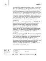
Three functional components are required to support interworking functions at the gateway:
the PSTN gateway switching centre (PGSC), the S-PCN gateway cell site switch (SGCSS)
and the S-PCN database (SDB) as shown in Figure 7.2. Their functions are briefly described
below.
†
PGSC: the PGSC provides PSTN access to the S-PCN network. SSN7 can be used to
Mobile Satellite Communication Networks248
Figure 7.1 S-PCN-PSTN signalling connection.
perform any signalling exchange between the PGSC and the SGCSS. All calls destined for
the S-PCN must be routed through this gateway.
†
SGCSS: in analogy to PGSC, the SGCSS provides S-PCN access to PSTN. Signalling
conversion between the S-PCN and SSN7 is also performed in this gateway. In addition,
interworking functions such as voice encoding, decoding and bit rate adaptation are also
supported in order to ensure end-to-end interoperability between the PSTN and the S-PCN
gateway.
†
SDB: this database contains information on the S-PCN mobile terminals such as the
location, terminal characteristics, service profiles, authentication parameters and so on.
Figure 7.2 depicts a scenario whereby a PSTN interfaces with other external networks. It is
also similar to that employed by GSM to interface with PSTNs. This approach has the
advantage that little or no modification is required in the PSTN.
Upon receipt of a call request from a PSTN subscriber, the PGSC informs the SGCSS of
such a request. The SGCSS then interrogates the SDB to check whether the called S-PCN
subscriber is attached to the network. If the S-PCN subscriber is attached to the network, the
called party’s location will be identified. Signalling conversion operation is then performed
by the SGCSS to translate the SSN7 call request from the PSTN to a S-PCN call request. The
call is then routed to the appropriate FES. If the addressed S-PCN user is unavailable, the
PSTN subscriber receives a notification, informing of the situation.
In the case when a call request is from an S-PCN subscriber, the SGCSS translates the
request to an SSN7 call request and signals the PGSC of such a request. The PGSC then
carries out relevant procedures to check if the called PSTN user is available. Appropriate
signalling is translated and exchanged between the two networks to inform the S-PCN caller
of the status of the call request through the two gateways.
7.2.3 Protocol Architecture of SSN7
7.2.3.1 Constituents
Before addressing the interworking features for signalling to interconnect the S-PCN and
PSTN, the call set-up and release procedures between the two networks need to be analysed.
Based on the assumption that the PSTN part will adopt the SSN7 signalling system, issues on
how the message transfer part (MTP), the signalling connection control part (SCCP) and the
Integrated Terrestrial-Satellite Mobile Networks 249
Figure 7.2 S-PCN-PSTN gateway function.
telephone user part
1
(TUP) of this signalling can support the S-PCN call establishment
procedures need to be investigated. As shown in Figure 7.3 [STA-95], the SSN7 signalling
system has been specified in four functional levels.
†
The MTP provides a reliable but connectionless service for routing messages through the
SSN7 network. It is made up of the lowest three layers of the open systems interconnection
(OSI) reference model. The lowest level, the signalling data link, corresponds to the
physical level of the OSI model and is concerned with the physical and electrical char-
acteristics of the signalling links. The signalling link level, a data link control protocol,
Mobile Satellite Communication Networks250
1
The TUP layer may not appear in some reference books. It is used here for discussions on plain old telephone
(POT) networks.
Figure 7.3 SSN7 signalling architecture.
provides reliable sequenced delivery of data across the signalling data link. It corresponds
to level 2 of the OSI model. The top level of the MTP is the signalling network level,
which provides for routing data across multiple signalling points (SP) from control source
to control destination. However, the MTP does not provide a complete set of functions
specified in the OSI layers 1–3, in particular, the addressing function and connection-
oriented service.
†
The SCCP is developed to enhance the connectionless sequenced transmission service
provided by the MTP by providing an addressing function and message transfer capabil-
ities. The addressing function is supported by the destination point codes (DPC) and
subsystem numbers (SSN). The addressing function is further enhanced by providing
mapping facilities to translate global titles, such as the dialled digits, into the DPC 1
SSN format in order to route messages towards a signalling transfer point. The SCCP and
the MTP together are referred to as the network service part (NSP). In the integrated
scenario, the SCCP is required to be capable of routing messages through different
networks based on different protocols in order to ensure interworking between the two
different networks.
†
Both the ISDN user part (ISUP) and the TUP form the user parts of the signalling system.
They provide for control signalling required in an ISDN and telephone network to handle
subscriber calls and related functions. They correspond to level 4 of the OSI structure.
The advantage of adopting signalling interworking using the SSN7 signalling architecture
is that it intrinsically allows the definitions of interworking functions to ensure end-to-end
interoperability between two different networks. This has also been the approach to inter-
connect PSTN with terrestrial mobile networks.
7.2.3.2 The MTP Layer
In order to provide interoperability with the SGCSS functional component in the S-PCN, the
implementation of the MTP in the PGSC has to take into account the interworking require-
ments with the equivalent layers in the SGCSS. In plain old telephone (POT) networks, the
MTP receives routing messages directly from the TUP, as shown in Figure 7.3, without
having an intermediate layer such as the SCCP required by the ISUP. The message format
of a routing label in the signalling information field of an SSN7 message signal unit consists
of three parts, as shown in Figure 7.4.
†
The signalling link selection (SLS): the value of the SLS is assigned by the user part in
level 4. For a given source/destination pair, several alternate routes may be possible. The
value of the SLS specifies the routing information. It is used to distribute traffic uniformly
among all possible routes.
Integrated Terrestrial-Satellite Mobile Networks 251
Figure 7.4 Routing label of SSN7.
†
The originating point code (OPC): this field contains information relating to the source
node such as the source address.
†
The destination point code (DPC): this field contains information about the destination
node such as the point code of the destination switch exchange. By means of the DPC,
each intermediate switching exchange during the routing process can decide whether the
message is destined for itself or whether it should be routed onward.
Since mobility is not supported in the PGSC, the mobile user’s address cannot be translated
into a recognisable DPC format by the PGSC during a call set-up procedure from the PSTN to
the S-PCN direction. In this case, the PGSC will simply forward all the outgoing messages to
the SGCSS, which will then query the SDB to obtain the mobile roaming data. Hence, in
order to ensure a correct addressing operation, the following procedures are carried out.
1. Upon receipt of a call set-up message from the PGSC indicating a PSTN to S-PCN call
establishment, the SGCSS associates the mobile user number with its roaming location
and prepares the DPC accordingly.
2. The SGCSS will also translate the OPC to its own format so that within the satellite
network itself, the OPC will refer to the SGCSS as the source address. In such a way,
all subsequent switching centres within the S-PCN will be processed as if they were S-
PCN messages.
3. The SGCSS will then translate the call set-up message into an initial address message
(IAM) for setting up an end-to-end signalling path.
Similar procedures will be carried out in the PGSC with call set-up in a direction from the
S-PCN to the PSTN.
7.2.3.3 SCCP Layer
For PSTNs that rely on the ISUP protocol, an SCCP layer is required to provide an inter-
mediate addressing level between the user part and the MTP layer. The SCCP routing
capabilities are supported by an international switching centre since they support ISUP
protocols for layer 4 of the signalling system. However, addressing in SCCP is based on
the global title, i.e. dialled digits, which is not supported by the SSN7 signalling network. The
global title must then be translated by the MTP into an appropriate DPC. Furthermore, the
SCCP layer implemented within the S-PCN will be tailored to its own requirements, which
may not fit into the SSN7 signalling format. As a result, interworking functions between the
PGSC and the SGCSS have to be carried out in order to translate the global address into the
appropriate DPC. The MTP layer carries out the normal addressing and routing procedures as
described in Section 7.2.3.2.
7.2.3.4 The TUP Layer
Although the TUP layer has been standardised by the ITU (Q.601–695), its implementation is
still catered towards each country’s switching network’s requirements. The information
transported by the TUP protocol which will have an impact on the interworking functionality
with S-PCN includes the called party address, calling party address, circuit identity and the
request of digital link (64 kps).
Mobile Satellite Communication Networks252
The called party address is identified by the called party’s telephone number. The number-
ing scheme adopted in this address will impact on the call set-up procedure. Two types of
numbering schemes can be implemented: A world-wide implementation with a common
country code scheme or a nation-wide operation. In the former approach, an international
switching centre (ISC) node has to be implemented to act as a gateway to the S-PCN network.
Referring back to Figure 7.2, the PGSC can act as the ISC. In the latter approach – the nation-
wide implementation – the numbering scheme is adopted as a specific PLMN identifier, which
forms part of the whole telephone number. This approach is adopted in existing GSM networks
within the same country. In this case, no ISC is required and all incoming traffic will be routed
towards the nearest S-PCN gateway (the SGCSS) through the PGSC. This numbering scheme,
however, requires at least one access point being accessible within each country.
The calling party address contains information on the calling party’s telephone number.
The PGSC provides this information upon receipt of a request from the SGCSS. The data
supplied will depend on the implementation of the numbering schemes by the S-PCN opera-
tors. If a unique country code scheme is adopted, this information will also have to be
supplied to the PSTN exchange.
The circuit identity specifies the characteristics of the signalling link established in the call
set-up process. In an integrated environment, for an S-PCN to PSTN call set-up, the SGCSS
will have a flag to indicate whether the communication is through the satellite or the terres-
trial links so that appropriate actions can be taken.
The request of digital link requires that both the calling party’s exchange and the called
party’s exchange must agree on the bit rate of the bi-directional digital circuit. This end-to-
end requirement may be mapped onto the interworking functionality in the PGSC/SGCSS
interface, in particular, the transcoding capabilities.
7.2.4 Access Functions
The access functions provide interconnection between an FES with an SCSS through the
PSTN in order to exchange information during call establishment, user registration/location
update and handover. Figure 7.5 shows the functional components for interworking access
functions between the S-PCN and PSTN [CEC-95]. Three main functional components are
involved:
†
S-PCN cell site switch (SCSS): the SCSS is responsible for the switching, service and
management functions between the S-PCN mobile terminals via the FES. It is normally
coupled to the local exchange to provide PSTN interface functionality, which depends on
Integrated Terrestrial-Satellite Mobile Networks 253
Figure 7.5 S-PCN-PSTN access function.
the connection type employed. There are two main types of connections: the dial-up type
connection or a permanent connection. The on-demand type is similar to the dial-up
connection, in which case the SCSS is coupled to the local exchange through one or
more POT connections. For the permanent connection, a wide-band connection is estab-
lished through the PSTN between the SCSS and the FES.
†
S-PCN database (SDB): the SDB is similar to the SDB described in Section 7.2.2.
†
Fixed Earth station (FES): the FES provides the interface between the S-PCN access
network and the mobile terminal. Similar to the SCSS, the FES is connected to the
local exchange through one or more POT connections or directly to the SCSS via a
permanent leased line connection.
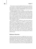
If dial-up connection is employed between the SCSS and the FES through the PSTN,
connection between the SCSS and the FES needs to be established whenever information
exchange takes place for different network procedures. This will introduce additional delay in
exchanging information between the SCSS and the FES. The additional delay may prove
significant in procedures such as registration, location update or handover. In addition, this
type of connection is analogue in nature and exchange of information will have to make use
of a dial-up modem, which may limit the data rates. On the other hand, if a permanent
connection is deployed, there is no need to establish connection between the SCSS and the
FES before any information exchange. Hence, no additional delay incurs. Furthermore, the
connection is digital in nature which can offer higher data rates than those offered with the on-
demand connection.
7.3 Integration with GSM
7.3.1 Introduction
In considering integration with GSM, the level of integration is the most important factor in
determining the integrated network architecture. Two approaches can be drawn in designing
such an integrated system: one is to modify the existing GSM infrastructure to suit the
peculiarity of the satellite system; or to adapt the satellite system to existing GSM networks.
As the development of GSM has already reached maturity, and future systems based on GSM,
such as GPRS and HSCSD, are already standardised, an integrated system which would
require significant modifications to existing GSM protocols or its infrastructure is seen as
impractical. Hence, the discussion that follows assumes adaptation of and modifications to
satellite network protocols for integration with the GSM network.
An integrated S-PCN and GSM system should aim to satisfy the user requirements as far as
possible but at the same time should also be feasible from the network operators’ perspective.
From the users’ perspective, the type of supported services and their quality, the authentica-
tion procedure and the charging mechanism form part of the user requirements. From the
network operators’ point of view, the requirements in interworking functions, the network
procedures and management functions are important issues to be considered for a successful
integration. Such requirements form the basis for the identification of possible integration
scenarios.
Before going into detail on the integration requirements and scenarios, Table 7.1
summarises the similarities and differences between the S-PCN and GSM networks, as
Mobile Satellite Communication Networks254
identified in Ref. [GMR-99]. They are based on the assumption that geostationary satellites
are deployed in the S-PCN.
Integrated Terrestrial-Satellite Mobile Networks 255
Table 7.1 Similarities and differences between a mobile-satellite network and a GSM network
Similarities – The frequency re-use concept adopted in the GSM network can be applied to
the S-PCN
– A satellite spot-beam coverage is equivalent to a GSM cell coverage
– Higher layer protocols of the GSM network may be adopted in the S-PCN with
possible modifications
Differences – Longer propagation delays in the S-PCN due to the long satellite-to-earth path
and to the longer distance between the FES and the user terminal
– Higher attenuation in the radio signal
– Larger variations in conversational dynamics in voice communications
– Increased echoes
– Delay in double-hop connection for mobile-to-mobile call may become
unacceptable
– A more sophisticated timing synchronisation scheme is required
– Higher attenuation in the radio signal in the satellite network due to the longer
propagation delay
– A spot-beam coverage is much larger than a terrestrial cellular coverage
resulting in lower inter-spot-beam handover probability. However, the benefits of
frequency re-use is diminished
– A power control mechanism is required in a satellite network as the satellite
power is shared by all the spot-beams over the entire coverage area This is
different from a base station power in a terrestrial network, which is not a shared
resource
– Line-of-sight operation is required in a satellite network in order to compensate
for the high attenuation in the radio signal in contrast to the use of multipath
signals in terrestrial cellular mobile networks (see Chapter 4). An alerting
procedure is required to inform users of any incoming calls when they are not in
line-of-sight with the satellite
– The satellite radio channel characteristics are described by the Rician channel
as opposed to the Rayleigh channel in terrestrial networks
– Adjacent cell interference in a terrestrial cellular network is a function of power
and cellular radius; whereas adjacent spot-beam interference is a function of
power and sidelobe characteristics of the satellite antenna array
– User terminals can access and be accessed by any one of the gateways in
satellite networks in contrast to terrestrial network access in which the user
terminal in any given cell can only access an MSC associated with that cell
– Optimum call routing is possible in satellite networks by routing the call to the
nearest gateway to the called party. This is impossible in existing GSM networks
– Do
¨
ppler shift can be considerable in a satellite network especially during the
initial period of operation
7.3.2 Integration Requirements
7.3.2.1 User Requirements
With GSM, the main services being provided are still very much voice-oriented. Future
mobile users will require a wider range of telecommunication services, including those of
messaging, voice communications, data retrieval and user controlled distribution services.
Different services and applications may cater for different user groups, which can be divided
into two main categories: business and private. It is expected that for business users, the
services requested will require wider bandwidth, for example, data retrieval, high resolution
image transmission, videoconferencing, etc. On the other hand, for private users, narrower
bandwidth services are envisaged. From the users’ perspective, the services provided have to
be user friendly, ubiquitous, low cost, safe and of an acceptable quality. This has several
implications:
1. User friendliness requires simple, easy-to-use and consistent human machine interface
(HMI) design for user access regardless of the terminal type and the supported services.
User interaction should be kept as low as possible. In the case of dual-mode terminals, the
HMI should be consistent for access to both networks, i.e. the same access procedures for
both networks and preferably the same user identity number for users to obtain access to
both networks.
2. Ubiquitous service provision implies users can access services anywhere at anytime. This
requirement has several impacts on the design of terminal equipment, the operating
environment and the level of mobility being supported by the networks, hence their
interworking functions in supporting mobility.
3. Terminal equipment can be broadly categorised into hand-held, portable and vehicular-
mounted devices [CEC-97]. It is important that terminals should remain lightweight and
compact for ease of carry and ease of storage. For vehicular-mounted terminals, this may
include group public terminals mounted on buses, coaches, aeroplanes or sea-liners. The
same HMI requirements as identified in point 1 above should apply to all terminal cate-
gories.
4. Ubiquitous coverage also implies that users can obtain access to services regardless of the
type of environment they are in, including indoor and outdoor environments; urban, sub-
urban and rural areas; motorways, railways, air and sea. This requires both networks to be
complementary to each other. For example, the satellite network may fill in ‘‘ holes’’ which
are not covered by the terrestrial network.
5. Ubiquity also implies that users should be able to roam between different geographical
areas, whether nation-wide or between countries. The ability to roam between the two
networks in the case of dual-mode terminal (DMT) users should also be possible.
6. Cost is perhaps one of the most important factors that has an impact on the popularity of
services. Needless to say, users require services that are good value for money. With this in
mind, different charging options should be made available to cater for specific user needs.
It is likely that there will be a significant difference in call charges and subscription fees
between the terrestrial and satellite networks. Technical aspects such as inter-segment
handover will require careful design and consideration in order to issue call charges when
the user is switched from one segment to another.
7. A safe and secure service encompasses technical aspects, such as user authentication,
terminal authentication, confidentiality of user profiles and location, ciphering and encryp-
Mobile Satellite Communication Networks256
tion, as well as health and safety issues, which may impose a limitation on the radiation
power on the user terminal.
8. The QoS supported by both networks should be as consistent as possible. Every effort
should be made to ensure the quality is compatible with that supported by the fixed
network.
7.3.2.2 Network Operator Requirements
Network operators require the network to function in an efficient manner and at the same time
to satisfy the customers’ needs. Network operations involve three main control functions: call
control, resource control and mobility control. In addition to these three control functions,
network management functions are required to monitor the performance of the network
operations as well as the maintenance of the network, i.e. the operation and maintenance
(OAM) functions. In an integrated network environment, interworking functions between
different networks are also required to ensure network inter-operability. The following gives
a list of what is considered to be important for the integrated system from a network oper-
ator’s point of view.
1. Modifications to existing standards or network infrastructure should be minimised. Thus,
in an integrated GSM-S-PCN network, significant modifications to the GSM system are
not expected. Hence, the definition of interworking functions and the implementation of
such interworking procedures will mainly concern the S-PCN part.
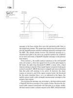
2. Call control procedures adopted in the GSM network should preferably be re-used in
the integrated network for compatibility. However, some of these procedures may not
be suitable for the satellite counterpart due to the longer propagation delays. For
instance, at least ten one-way [CEC-95] information exchanges between the BSS and
the MT are required for call set-up in a GSM network. This will not be feasible in a
geostationary satellite network in which a one-way transmission delay of about 270 ms
will be incurred.
3. Resource control procedures are important in any radio network as the radio resource is
scarce. This is especially so when satellite networks are considered. Depending on the
level of integration, network resources in the terrestrial network and those in the satellite
network can be shared so that overflow traffic can be redirected to the satellite network and
vice versa. This may require special switching functionalities to be implemented in both
the S-PCN and GSM networks in order to switch traffic between the two.
4. Mobility control procedures encompasses handover, location management, paging and
call delivery. In an integrated network, the possibility of inter-segment handover should be
taken into account. If inter-segment handover is considered, the call set-up procedure and
the resource control mechanism will also need to take into account such handover mechan-
isms. The location management procedures in a satellite network will be different from
that in the GSM network as discussed in Chapter 6. Hence, to ensure mobility between the
two networks, an important interworking goal is to provide compatibility between network
location registers. This implies that the numbering and addressing schemes need to be
compatible between the two systems. This requires an examination of the feasibility of
adopting existing GSM numbering and addressing schemes to the requirements of S-PCN
operations. This may decide whether S-PCN would adopt a GSM-like numbering system
Integrated Terrestrial-Satellite Mobile Networks 257
or whether a completely new scheme is required. Furthermore, the protocols used between
location registers is also required to be examined. In GSM systems, MAP protocols are
used to support mobility. Whether this or other protocols such as INAP will be adopted in
S-PCN requires a close examination on the suitability of their use.
5. Signalling in all the above mentioned network control procedures should be minimised
since this will consume both the frequency spectrum as well as the satellite power.
Excessive signalling also increases signalling load and delay. This would affect the
network efficiency as well as the QoS.
7.3.3 Integration Scenarios
7.3.3.1 Integration Levels
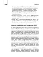
When considering the re-use of the GSM network architecture and structure, the equivalent
counterparts of the S-PCN are indicated in Figure 7.6, where the use of ‘G’ in the acronyms
refers to Gateway. Four levels of integration are depicted in the figure.
1. Integration at the Abis-interface – separate BTS/GTS, common BSC and common MSC.
2. Integration at the A-interface – separate BTS/GTS and BSC/GSC, common MSC.
3. Integration at the E-interface – separate terrestrial and satellite networks but with inter-
working functions between the MSCs.
4. Integration at the Um-interface – terminal integration.
In the above, the terminology adopted by ETSI is used to illustrate the satellite components
of the network, that is GTS, GSC and GMSC.
7.3.3.2 Integration at the Abis-Interface
In this integration scenario, apart from the two different transceiver systems, the other
network components are shared between the two networks as depicted in Figure 7.7. Inter-
working functions between the two segments will have to be defined at both the Abis- and A-
interfaces.
With different transceiver systems, the air interfaces in the respective segments can be
optimised to suit the transmission characteristics of the individual propagation channels.
Mobile Satellite Communication Networks258
Figure 7.6 S-PCN-GSM integration scenarios.
Since the BSC and the MSC are common to both networks, inter-network control functions
such as inter-network mobility control, resource control and switching functions are easier to
co-ordinate. Since the MSC is common to both networks, the HLR and VLR are available to
both networks. This allows quick and complete access to all location registration information.
Due to the different transceiver systems, the QoS supported by one segment may not be
consistent with the other segment. Furthermore, a common BSC and MSC implies that extra
functions need to be implemented in these two network components in order to cater for the
specific needs required by the satellite network, unless the same Abis-interface is implemen-
ted in both networks. This may require modifications to existing GSM standards, which are
not considered likely. Although inter-network control functions are easier to co-ordinate, the
design of the switching functions and control functions in the centralised BSC and MSC may
not be optimum for each individual segment. For example, a fast switching between two
BTSs within the same segment may not be possible. Since the BSC and MSC are responsible
for the co-ordination of both segment specific and inter-segment network control functions,
extra signalling functionalities are required to be carried out by the MSC which again would
require modifications to the GSM standard.
7.3.3.3 Integration at the A-Interface
In this integration scenario, the satellite gateway provides functionalities similar to those of
the BTS and the BSC of the GSM network. Figure 7.8 depicts this integration scenario.
Similar to the previous integration scenario, air interfaces can be optimised for each
Integrated Terrestrial-Satellite Mobile Networks 259
Figure 7.7 Integration at the Abis-interface – common BSC.
Figure 7.8 Integration at the A-interface – common MSC.
individual segment. Switching functionalities at the BSC and the GSC can be optimised for
individual segments to enable quick switching between different BTSs or GTSs within the
same segment. A single MSC can ease co-ordination of inter-network control functions,
especially for inter-segment handover. Furthermore, as before, a common HLR and a
common VLR implies full access to location registration information. This will ease signal-
ling exchanges for subscriber data between different segments. The only drawback of this
integration scenario is that modifications to the A-interface and the MSC are required in order
that the MSC can establish signalling exchanges with both the GSM and the satellite access
network. This implies that the functionality of the MSC may not be at an optimum for each
individual segment.
7.3.3.4 Integration at the E-Interface
In this integration scenario, the GSM and S-PCN segments will have their own access
networks, and each access segment will have a common network infrastructure as shown
in Figure 7.9. This will enable calls to be routed transparently between the different access
networks. With this level of integration, both networks can share a common HLR while
maintaining a separate VLR. This common networking infrastructure allows transparent
fixed user to mobile user connections since a unique calling number can be assigned to the
mobile user regardless of the different segments. A single satellite gateway can be shared
among different GSM networks with the satellite transponder capacity being dynamically
shared among different traffic stations. In this respect, the satellite network operators may be
considered as the provider of a common set of services to different service providers. Inter-
working functions between the two networks needs only be defined at the E-interface, provid-
ing switching and resource control functions between the two segments. The only
modification to existing GSM standards is envisaged to be at the E-interface, if the function-
alities of the GMSC and the MSC are not identical.
Mobile Satellite Communication Networks260
Figure 7.9 Integration at the E-interface – separate MSC.
7.3.3.5 Integration at the Um-Interface
This scenario has to be differentiated from other integration scenarios in which a dual-mode
terminal is also required for dual-mode access. In this scenario, there is no integration
between any network elements of the two networks. The only common point for the two
mobile networks is at the dual-mode terminal as depicted in Figure 7.10.
Segment selection will be performed during the call set-up stage. As there is no common
network elements shared between the two networks, the dual-mode terminal merely serves
the purpose of enabling users to obtain access to both segments. If roaming between the
different networks is supported, a common HLR is required, which will then reduce the
integration scenario to that of the split MSC integration option. Handover of calls between
the two networks may only be possible when sufficient intelligence is implemented in the
terminal such that handover of calls between the two networks will be controlled by the
mobile, i.e. mobile controlled handover (MCHO). This will increase the complexity and the
cost of the terminal.
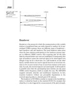
7.3.4 Impact of Integration Scenarios on the Handover Procedure
In this section, only integration scenarios at the E- and A-interfaces are considered.
7.3.4.1 Integration at the E-interface Level
Referring back to Figure 7.9, which shows the integrated S-PCN/GSM network architecture
at the E-interface, i.e. the S-PCN and GSM networks are stand-alone networks. In this figure,
the HLR and VLR associated with the GSM network contain dual-mode user information,
whereas the S-HLR and S-VLR contain information on subscribers registered to S-PCN only.
Dual-mode users are managed by the GSM operators and are assigned with a GSM MSISDN
number. Any calls from the fixed network to a dual-mode user will be routed through the
GSM MSC by identification of the GSM MSISDN number. The impact of such an integration
on handover, location management and call control functions are described below.
Impact on Handover From a GSM Cell to a Satellite Spot-Beam Using GSM
Protocol GSM adopts mobile assisted handover (MAHO) as the handover controlling
scheme, i.e. both the mobile station and the network monitors the received signal strength
Integrated Terrestrial-Satellite Mobile Networks 261
Figure 7.10 Integration at the Um-interface.
and the channel quality but the handover decision is made by the network. Furthermore,
backward handover is adopted as the connection establishment scheme. Assuming that the
GSM protocol is adopted as the baseline protocol for the integration scenario, Figure 7.11
shows the handover signalling flow. Due to the different network features and propagation
delays, some parameters at the A-interface will have to be modified. In particular, a need for
modification in the ‘‘ Handover request’’ and ‘‘ Handover request ack’’ messages have been
identified. Furthermore the impact on handover interruption time due to the propagation delay
difference between the GSM and satellite networks is also examined.
Modifications to Handover Request Message The ‘‘ Handover request’’ message is a BSS-
MAP message sent from the GMSC to the GWS. The information elements contained in the
user data field of this message come mostly from the message ‘‘ perform handover’’ , which is
sent by the GSM MSC to the GMSC. Some information elements are mandatory with fixed
length while others are optional, as shown in Table 7.2 [CEC-95]. The effects of integration
on three of these information elements are particularly discussed, namely, the serving cell
identifier, the target cell identifier and the radio channel identity.
The serving cell identifier uniquely identifies the serving cell. Table 7.3 shows the format
of this information field. In particular, the cell identification discrimination field indicates the
whole or part of the cell global identification (CGI), which includes the mobile country code
(MCC), mobile network code (MNC), location area code (LAC) and the cell identity (CI). For
GSM, if handover occurs in different location areas, the LAC is used; whereas CI will be used
if handover occurs in the same location area. The whole CGI is used when inter-PLMN
handover occurs, which is not envisaged in the GSM handover process, although this option is
provided. In an integrated S-PCN/GSM system, there may be more than one PLMN under the
coverage area of a single satellite spot-beam. Hence, CGI will have to be used in order to
uniquely identify a GSM cell. This implies that the GMSC will have to be responsible for
translating the LAC, which was passed from the GSM-MSC to the GMSC in the ‘‘ perform
handover’’ message, into a CGI.
The target cell identifier identifies the spot-beam, the format of which is the same as that of
the serving cell identifier. In order to uniquely identify the spot-beam, the satellite identifier
number in the satellite constellation and the spot-beam number need to be identified. In
addition, it also needs to distinguish the satellite network from the terrestrial network.
Under this situation, it will be convenient to use the location area identifier (LAI), which
includes the MCC, MNC and LAC. However, the meanings of the MCC and MNC will be
different from those in the serving cell identifier. For example, the MCC can be used to
identify that the target cell is in a satellite network, the MNC to identify the satellite number
and the LAC to identify the spot-beam number.
The radio channel identity identifies the allocated radio channel. In GSM, this information
element is optional and is only used for OAM purposes. The channel resource allocation
function is performed by the base station. The MSC will not control such an allocation. In a
satellite network, depending on the network architecture and functions, there could be the
possibility that the MSC will be responsible for the allocation of channels for incoming calls
and handover functions in order to improve resource utilisation efficiency. In this case, this
information element will become mandatory in the integrated system. There are four fields in
this information element: the channel descriptor, the frequency channel sequence, the mobile
allocation and the starting time. The channel descriptor identifies the slot number and the
frequency number. The slot number may remain unchanged if the GSM TDMA frame length
Mobile Satellite Communication Networks262
Integrated Terrestrial-Satellite Mobile Networks 263
Figure 7.11 Signalling flow for a GSM cell to a satellite spot-beam handover for integration at the
E-interface [CEC-95].
is adopted in the satellite network. The maximum frequency number, however, may be
subject to change, if the satellite network has more than 256 carriers, as opposed to the
124 carriers in GSM.
Modifications to Handover Request Ack Message This message is again a BSS-MAP
message and is sent from the GWS to the GMSC to indicate that the handover request can be
supported by the GWS. It will also indicate the radio channel to which the MT is assigned.
The user data field in this message contains two information elements: the message type and
layer 3 information, as shown in Table 7.4.
The message type is mandatory and is of length 1 octet. The layer 3 information field is also
mandatory, the length of which varies from 9 to 56 octets. It contains the radio interface
handover command message, which is then carried forward from the GMSC to the GSM-
Mobile Satellite Communication Networks264
Table 7.2 Information elements in the ‘‘ handover request’’ message in GSM
Information elements Type (M: mandatory;
O: optional)
Length (octet)
Message type M 1
Channel type M 5
Encryption information M 3–20
Classmark information: 1 or 2 M 2 or 4
Serving cell identifier M 5–10
Priority O 3
Circuit identity code O 3
Radio channel identity O 5–38
Downlink DTX flag O 2
Target cell identifier O 3–10
Interference band O 2
Table 7.3 Serving cell identifier field format
Information elements Length (octet)
Element identifier 1
Length 2
Cell identification discrimination 3
Cell identification 4–10
Table 7.4 Handover request ack message format
Information elements Type Length (octet)
Message type M 1
Layer 3 information M 9–56