BS 5306 6 2 1989 fire extinguishing installations and equipment on premises
Bạn đang xem bản rút gọn của tài liệu. Xem và tải ngay bản đầy đủ của tài liệu tại đây (637.32 KB, 28 trang )
BRITISH STANDARD
Fire extinguishing
installations and
equipment on
premises —
Part 6: Foam systems —
Licensed copy:RMJM, 30/08/2005, Uncontrolled Copy, © BSI
Section 6.2 Specification for medium
and high expansion foam systems
UDC 614.842.6:614.844.5
BS 5306-6.2:
1989
BS 5306-6.2:1989
Committees responsible for this
British Standard
Licensed copy:RMJM, 30/08/2005, Uncontrolled Copy, © BSI
The preparation of this British Standard was entrusted by the Fire Standards
Policy Committee (FSM/-) to Technical Committee FSM/13, upon which the
following bodies were represented:
Association of Metropolitan Authorities
British Automatic Sprinkler Association
British Fire Protection Systems Association Ltd.
British Fire Services’ Association
British Gas plc
British Nuclear Fuels Limited
Chief and Assistant Chief Fire Officers’ Association
Confederation of British Industry
Convention of Scottish Local Authorities
Department of Health and Social Security
Department of the Environment, Building Research Establishment
(Fire Research Station)
Department of the Environment (Property Services Agency)
Department of Transport (Marine Directorate)
Electricity Supply Industry in England and Wales
Engineering Equipment and Materials Users’ Association
Fire Brigades Union
Fire Extinguishing Trades Association
Health and Safety Executive
Hevac Association
Home Office
Incorporated Association of Architects and Surveyors
Institution of Fire Engineers
Institution of Gas Engineers
Loss Prevention Council
Ministry of Defence
Royal Institute of British Architects
Society of Fire Protection Engineers
Society of Motor Manufacturers and Traders Limited
United Kingdom Atomic Energy Authority
This British Standard, having
been prepared under the
direction of the Fire
Standards Policy Committee,
was published under the
authority of the Board of BSI
and comes into effect on
31 January 1989
© BSI 02-1999
The following BSI references
relate to the work on this
standard:
Committee reference FSM/13
Draft for comment 87/44827 DC
ISBN 0 580 17018 7
Amendments issued since publication
Amd. No.
Date of issue
Comments
BS 5306-6.2:1989
Licensed copy:RMJM, 30/08/2005, Uncontrolled Copy, © BSI
Contents
Page
Committees responsible
Inside front cover
Foreword
ii
Section 1. General
0
Introduction
1
1
Scope
1
2
Definitions
1
3
Characteristics of medium and high expansion foam
2
4
Classification of flammable liquids
3
5
Types of system
4
6
Planning
4
Section 2. Contract arrangements
7
Contract drawings
5
8
Extensions and alterations
5
9
Commissioning and acceptance tests
5
Section 3. Periodic inspection, testing and maintenance
10 Inspection
7
11 Service and maintenance schedule
7
Section 4. System design
12 General
8
13 Foam quality
8
14 Water supplies, pumps and drainage
8
15 Foam concentrate and solution
9
16 Components and pipework
10
17 Operation
11
Section 5. Specific types of system
18 Medium expansion foam systems
16
19 High expansion foam systems
17
Appendix A Classification of foam concentrates
20
Appendix B Determination of application rate (medium expansion)
and foam discharge rate (high expansion)
20
Appendix C Determination of expansion
21
Appendix D Determination of percentage concentration
21
Figure 1 — Sign for display at manual control
13
Figure 2 — Signs for display at entrances to hazard
14
Table 1 — Minimum discharge times for medium expansion
foam systems discharging at the minimum rate
16
Table 2 — Maximum submergence times for high expansion
foam systems
19
Publications referred to
Inside back cover
© BSI 02-1999
i
BS 5306-6.2:1989
Licensed copy:RMJM, 30/08/2005, Uncontrolled Copy, © BSI
Foreword
This Section of BS 5306 has been prepared under the direction of the Fire
Standards Policy Committee.
The other Parts of BS 5306 in preparation or published are as follows:
— Part 0: Guide for the selection of installed systems and other fire equipment;
— Part 1: Hydrant systems, hose reels and foam inlets;
— Part 2: Sprinkler systems;
— Part 3: Code of practice for selection, installation and maintenance of
portable fire extinguishers;
— Part 4: Specification for carbon dioxide systems;
— Part 5: Halon systems;
— Section 5.1: Halon 1301 total flooding systems;
— Section 5.2: Halon 1211 total flooding systems;
— Part 6: Foam systems;
— Section 6.1: Specification for low expansion foam systems;
— Part 7: Specification for powder systems.
Medium and high expansion foam systems are designed to provide a supply of
foam for the extinction of fire.
The requirements and recommendations of this Section of BS 5306 are made in
the light of the best technical data known to the committee at the time of writing,
but since a wide field is covered it has been impracticable to consider every
possible factor or circumstance that might affect implementation of these
recommendations.
To comply with this standard, the user has to comply with all its requirements.
He may depart from recommendations, but this would be on his own
responsibility and he would be expected to have good reason for doing so.
It has been assumed in the preparation of this standard that the execution of its
provisions is entrusted to people appropriately qualified and experienced in the
specification, design, installation, testing, approval, inspection, operation and
maintenance of foam systems and equipment, for whose guidance it has been
prepared.
A classification of foam concentrates is given in Appendix A.
A British Standard does not purport to include all the necessary provisions of a
contract. Users of British Standards are responsible for their correct application.
Compliance with a British Standard does not of itself confer immunity
from legal obligations.
Summary of pages
This document comprises a front cover, an inside front cover, pages i and ii,
pages 1 to 22, an inside back cover and a back cover.
This standard has been updated (see copyright date) and may have had
amendments incorporated. This will be indicated in the amendment table on
the inside front cover.
ii
© BSI 02-1999
BS 5306-6.2:1989
Section 1. General
Licensed copy:RMJM, 30/08/2005, Uncontrolled Copy, © BSI
0 Introduction
2 Definitions
It is important that the fire protection of a building
or plant should be considered as a whole. Foam
systems can form only a part, though an important
part, of the available facilities, but it should not be
assumed that their provision necessarily removes
the need to consider other measures, such as the
provision of portable fire extinguishers or other
mobile appliances for first aid or emergency use, or
to deal with special hazards.
Foams have for many years been recognized
effective media for the extinction of fires. In
particular, medium expansion foams have been
developed for the extinction of both flammable
liquid and solid fuel fires, and high expansion foam
for use against solid fuel fires and to a lesser extent
flammable liquid fires. In the planning of a
comprehensive fire protection scheme, it should not
be forgotten that there may be hazards for which
foams are not suitable or there may be dangers in
their use which require special precautions.
Advice on these matters can be obtained from the
appropriate fire authority, the Health and Safety
Executive or other enforcing authority under the
Health and Safety at Work etc. Act 1974, and the
insurers. In addition, reference should be made
to BS 5306-0 and as necessary to other Parts of this
standard.
It is essential that fire extinguishing equipment
should be carefully maintained to ensure instant
readiness when required. This routine is liable to be
overlooked or given insufficient attention by
supervisors. It is, however, neglected at peril to the
lives of occupants of the premises and at the risk of
crippling financial loss. The importance of
maintenance cannot be too highly emphasized.
For the purposes of this Section of BS 5306, the
definitions given in BS 4422-4 apply together with
the following.
1 Scope
This Section of BS 5306 specifies requirements and
gives recommendations for the design, installation
and maintenance of fixed and semi-fixed systems;
ancillary portable or transportable equipment
provided as part of a pre-planned scheme for
applying medium and high expansion foam to fires
in buildings, industrial plant and storage facilities.
Application rates are specified for medium
expansion foam to flammable liquid fires, and for
high expansion foam to flammable liquid fires and
combustible solid fires.
NOTE 1 Unless otherwise specified in this standard all
pressures are gauge pressures and are expressed in bars
1 bar = 105 N/m2 = 102 kPa.
NOTE 2 The titles of the publications referred to in this
standard are listed on the inside back cover.
© BSI 02-1999
2.1
competent person
a person capable of carrying out the inspection and
maintenance procedures of clause 11, by reason of
experience and access to the requisite information,
tools and equipment
2.2
concentration
the ratio of foam concentrate in the foam solution
usually expressed as a percentage by volume
2.3
expansion (expansion ratio)
the ratio of the volume of aerated foam to the
volume of foam solution from which it was made
2.4
high expansion foam generator
a foam-making component in which air is forced
through a gauze screen that is sprayed with foam
solution to make the foam
2.5
medium expansion foam branchpipe
a hand-held self-aspirating foam-making
component that produces foam with an expansion in
the range 21 to 200
2.6
medium expansion foam monitor
a self-aspirating foam-making component that
produces foam with an expansion in the
range 21 to 200, at a rate of substantially greater
than that of a hand-held branchpipe
NOTE A monitor is usually supported on a swivel mounting
which is either connected to fixed pipework or may be mounted
on a mobile wheeled or skid unit.
2.7
self-aspirating foam-making component
foam-making component in which air is induced by
the discharge of foam solution from a nozzle or
nozzles within the equipment. The induced air is
mixed intimately with the foam solution within the
equipment to produce the foam
2.8
user
the person(s) responsible for or having effective
control over the fire safety provisions in or
appropriate to the premises or building
1
BS 5306-6.2:1989
3 Characteristics of medium and high
expansion foam
3.1 General
Foam systems shall produce foam as an aggregate of
gas filled bubbles from an aqueous solution of a
foam concentrate.
COMMENTARY AND RECOMMENDATIONS ON 3.1. The
gas is usually air.
Licensed copy:RMJM, 30/08/2005, Uncontrolled Copy, © BSI
3.2 Uses
The requirements of this standard apply to medium
and high expansion foams suitable for extinguishing
fires in combustible solids, flammable liquids, or
combinations of both.
COMMENTARY AND RECOMMENDATIONS ON 3.2.
Medium expansion foam may be used on
combustible solids up to a height of about 3 m, either
by direct application to the solid surfaces or by total
submersion. It operates by excluding air from the
combustibles, and by wetting down the burning
surfaces. It is useful in outdoor conditions, for
example on bund fires, provided the wind speed is
not greater than about 10 m/s and is not gusty. The
foam may be laid gently upon the surface of a fire, or
can be projected as a stream, according to the design
of the application equipment.
Medium expansion foam is effective on hydrocarbon
liquid fires but, except for the alcohol resistant type,
is generally not suitable for use on foam destructive
liquids which cause rapid breakdown of the foam.
High expansion foam is used most effectively in
indoor spaces where it can be used to submerge a
combustible solid or flammable liquid fire and
exclude the air needed for combustion. Because it has
a relatively low water content per unit volume it does
not have a great cooling effect, e.g. on solid surfaces,
and the extinction process therefore depends mostly
on smothering the fire. It is capable of extinguishing
fires of considerable vertical extent, e.g. in
high-racked storages up to at least 10 m, provided
that the foam can be applied from above the fire site
and horizontal transit to the site is minimized. Some
destruction of the foam by the fire will occur which
can be compensated by an increased application
rate. A solid fuel fire submerged in high expansion
foam is not necessarily extinguished quickly, but can
smoulder beneath the foam surface for a
considerable time until the drainage of water from
the foam cools the combustible surfaces to below
ignition temperature. High expansion foam is most
valuable in total flooding of places where it is
inadvisable for personnel to go during firefighting,
e.g. in underground storage facilities or basements.
2
3.3 Expansion
3.3.1 Medium expansion foam. Medium expansion
foam shall have an expansion between 21 and 200.
3.3.2 High expansion foam. High expansion foam
shall have an expansion between 201 and 1 000.
COMMENTARY AND RECOMMENDATIONS ON 3.3. Foams
are arbitrarily subdivided into three ranges of
expansion.
Low expansion foam (LX): expansion up to 20
Medium expansion foam (MX): expansion 21
to 200
High expansion foam (HX): expansion 201
to 1 000
3.4 Application method
3.4.1 Medium expansion. Medium expansion foams
shall be applied:
a) gently to the surface of a flammable liquid or
solid combustible fire; or
b) by means of a medium expansion foam
branchpipe or monitor.
COMMENTARY AND RECOMMENDATIONS ON 3.4.1. The
first method is suitable for fixed systems where the
location, size and shape of the hazard is known, and
the system can be designed to meet this requirement.
The second method is more appropriate where the
size and location of the hazard may vary with
circumstance, and needs to be dealt with by a more
flexible approach.
3.4.2 High expansion. High expansion foams shall
be applied:
a) by filling the volume in which the fire occurs; or
b) by guiding a wall of foam in the direction of a
localized fire, in order to submerge and suppress
it.
The foam may be introduced directly, or through
flexible ducting.
COMMENTARY AND RECOMMENDATIONS ON 3.4.2. High
expansion foam, by its nature, can only be applied
gently to fires. Method a) is generally preferable as
the water content of the foam needs to be retained as
far as possible to ensure heat resistance at the fire.
Horizontal movement at floor level promotes water
drainage and degrades the foam quality. To make
high expansion foam effective in large compartments
and up to heights of 10 m, flexible barriers may be
used to retain the foam in the required area and to
permit its fast build up to the required height.
Wherever possible foam should be applied at a high
level, i.e. above the level of foam in the fire space.
© BSI 02-1999
BS 5306-6.2:1989
Licensed copy:RMJM, 30/08/2005, Uncontrolled Copy, © BSI
3.5 Potential hazards
3.7 Compatibility of foam concentrates
Foam systems shall include provision to minimize
the danger when foam is applied to liquids
above 100 °C, energized electrical equipment or
reactive materials.
COMMENTARY AND RECOMMENDATIONS ON 3.5. Since
all foams are aqueous solutions, their application to
burning flammable liquids in depth, where the
temperature of the liquid exceeds 100 °C, may be
accompanied by the danger of frothing or slop-over of
the burning liquid, due to the boiling of the water
draining from the foam, as it passes through the hot
layers of liquid. This danger will apply to medium
expansion foam as well as to low expansion foam
(see BS 5306-6.1), but is is probable that in these
circumstances, the lower water content of the
medium expansion foam may be largely evaporated
on contact with the flammable liquid surface,
reducing the danger significantly. High expansion
foam is not used in this type of application.
Because foams are made from aqueous solutions,
they may be dangerous to use on materials which
react violently with water, such as sodium or
potassium, and should not be used when these are
present. A similar danger is presented by other
metals, such as zirconium or magnesium, only when
they are burning.
Medium and high expansion foams are electrically
conductive, and should not be used on energized
electrical equipment, where this would be a danger
to personnel (see 19.6).
Personnel should not enter spaces filled with high
expansion foam see 19.6).
Foam concentrate (or solution) added or put into a
system shall be suitable for use and compatible with
any concentrate (or solution) already present in the
system.
COMMENTARY AND RECOMMENDATIONS ON 3.7. Foam
concentrates, and foam solutions, even of the same
class, are not necessarily compatible, and it is
essential that compatibility be checked before mixing
two concentrates or premixed solutions.
3.6 Compatibility with other extinguishing
media
The foam produced by the system shall be
compatible with any media provided for application
at or about the same time as foam.
COMMENTARY AND RECOMMENDATIONS ON 3.6.
Certain wetting agents and some extinguishing
powders may be incompatible with foams, causing a
rapid breakdown of the latter. Only media that are
substantially compatible with a particular foam
should be used in conjunction with it.
Water jets or sprays may adversely affect a foam
blanket, but the simultaneous application of water
from sprinklers can be beneficial provided that
allowance is made for the increased breakdown of
foam (see commentary and recommendations
on 19.4).
4 Classification of flammable liquids
4.1 Flashpoint
For the purposes of this standard flammable
hydrocarbon liquids are classified into those with:
a) flash points up to and including 40 °C;
b) flash points above 40 °C.
when determined in accordance with BS 2000-34.
COMMENTARY AND RECOMMENDATIONS ON 4.1. It is
important to note that other classifications may use
different methods of flash point determination and
divide the classes at other temperatures.
Tanks containing liquids with flash points much
above 60 °C are not normally protected by fixed foam
systems unless these liquids are heated above
ambient temperature.
4.2 Foam destructiveness
For the purposes of this standard when considering
foam destructiveness, flammable liquids are
considered as falling into two groups:
a) hydrocarbons, and those non-hydrocarbon
liquids which are not more foam destructive than
hydrocarbons;
b) foam destructive liquids, which are generally
water soluble and which are much more foam
destructive than hydrocarbons.
COMMENTARY AND RECOMMENDATIONS ON 4.2.
Special types of concentrate are used for foam
destructive liquids. Higher rates of application are
specified for foam destructive liquids than for
hydrocarbons and it is usually essential to use gentle
application methods.
The degree of foam destructiveness varies however,
and isopropyl alcohol, butyl alcohol and isobutyl
methyl ketone, methyl methacrylate monomer and
mixtures of water-miscible liquids in general may
require higher application rates.1)Protection of
products such as amines and anhydrides which are
particularly foam destructive require special
consideration.
1)
The preferred names for isopropyl alcohol, butyl alcohol and isobutyl methyl ketone are propan-2-ol, butan-1-ol
and 4-methylpentane-2-one respectively.
© BSI 02-1999
3
BS 5306-6.2:1989
5 Types of system
5.4 Portable systems
5.1 General
Portable systems shall have foam producing
equipment that can be carried by one or more men
and connected via fire hose to a pressurized water or
premixed solution supply.
For the purposes of this standard foam systems are
considered as being of the fixed, semi-fixed, portable
or transportable type and shall comply
with 5.2 to 5.5 as appropriate.
COMMENTARY AND RECOMMENDATIONS ON 5.1. A
foam system consists of a water supply, a supply of
foam liquid concentrate, a device to proportion
correctly the water and foam concentrate, and
pipework or hose connected to equipment to make
and to distribute foam over the hazard.
Self-contained systems are those in which all
components and water and foam concentrate,
separately or as premixed solution, are contained
within the system. Such systems usually use
compressed gas to provide pressurization at the time
of operation.
5.2 Fixed systems
Licensed copy:RMJM, 30/08/2005, Uncontrolled Copy, © BSI
Fixed systems shall have permanent pipework
connecting the water supply via the fire water pump
(if fitted) and foam liquid proportioning device to the
foam maker(s) which protect the hazard.
5.3 Semi-fixed systems
Semi-fixed systems shall have permanent pipework
from the foam maker(s) which protect the hazard to
an area, adjacent to the hazard, where it is
considered safe for personnel to conduct fire fighting
operations.
COMMENTARY AND RECOMMENDATIONS ON 5.3. This
pipework may include the proportioning device. The
water supply to the pipework is via hoses and is
usually pumped by mobile fire appliances. The area
adjacent to the hazard should be outside any bunded
area and at least one tank diameter or 15 m,
whichever is the greater, from any tank. The inlet to
the fixed pipework should be fitted with corrosion
resistant metal connections provided with plugs or
caps and should be marked by a notice reading
“Foam inlet — for firefighting use only”.
4
5.5 Transportable systems
Transportable systems shall have foam producing
equipment mounted on wheels or skids.
COMMENTARY AND RECOMMENDATIONS ON 5.5. These
may be self-propelled, towed by a vehicle or pushed
by hand. These units are for connection via hoses to
a water or foam solution supply.
6 Planning
Where a foam extinguishing system is being
considered for new or existing buildings or plant the
following shall be consulted:
a) the fire authority;
b) other appropriate public authorities;
c) the insurers.
COMMENTARY AND RECOMMENDATIONS ON CLAUSE 6.
The authorities mentioned above should be informed
as early as possible of the type of foam system to be
installed and the system design engineers should be
fully informed of the protection required in any area.
There may be statutory or local bye-law
requirements and other requirements of these
authorities which should be co-ordinated in the
planning stages of the contract.
© BSI 02-1999
BS 5306-6.2:1989
Section 2. Contract arrangements
Licensed copy:RMJM, 30/08/2005, Uncontrolled Copy, © BSI
7 Contract drawings
9 Commissioning and acceptance tests
Prior to installation, contract drawings and
specifications shall be prepared and submitted to
the relevant authority for approval. These shall be
to scale or be fully dimensioned with sufficient
detail to define clearly both the hazard and the
proposed system. Details of the hazards shall be
included to show the materials present, the location
and/or limits of the hazard and any other materials
that are likely to become exposed to the hazard in
the event of a fire.
The following details of the proposed system shall be
included on the contract drawings:
a) the purpose and function of the system;
b) the application rate and the duration of
discharge of the system, and the appropriate
minimum values of this standard;
c) hydraulic calculations;
d) the pipework including support details;
e) the detection system layout (if specified) and
method of operation;
f) the type, location and spacing of foam discharge
devices;
g) the type and location of foam proportioning
devices;
h) the source of water and quantity needed;
i) the quantity and type of foam concentrate, its
design concentration, the method of storage and
the quantity to be held in reserve.
9.1 General
8 Extensions and alterations
Any extension or alteration to an existing system
complying with this standard shall also comply with
the appropriate requirements of this standard.
COMMENTARY AND RECOMMENDATIONS ON CLAUSE 8.
Any extension or alteration to the foam installation
should be carried out by the installer or his agent.
The organization that services the system and the
relevant authorities should be notified promptly of
any alteration.
The effect on available water supply and minimum
required quantity of foam concentrate should be
considered at the design stage of extension or
alteration to a system, and full hydraulic
calculations should be carried out on the new system
layout prior to commissioning.
The installer of the system or his supervising
supplier shall arrange for the completed system to
be inspected and tested to determine that it is
properly installed and that it will function as
designed to the satisfaction of the user and the
relevant authorities. A commissioning test
programme shall be submitted by the installer to
the user.
9.2 Inspection
A visual inspection shall be conducted to ensure
that the system has been installed correctly. All
normally dry horizontal pipework shall be inspected
for drainage pitch (see 16.2.4).
COMMENTARY AND RECOMMENDATIONS ON 9.2.
Inspection should check for conformity with design
drawings and specifications, continuity of pipework,
removal of temporary blinds, accessibility of valves,
controls and gauges and proper installation of foam
makers, vapour seals and proportioning devices. All
equipment should be checked for correct
identification and operating instructions.
Water supply pipework, both underground and
above ground, should be flushed thoroughly at the
maximum practicable rate of flow, before connection
is made to system piping, in order to remove foreign
materials which may have entered during
installation or which may have accumulated in the
mains systems at lower rates of flow. The minimum
rate of flow for flushing should be not less than the
water demand rate of the system.
Foam concentrates have a lower surface tension than
water, and they may cause internal pipe scale or
sediment to loosen with the risk of blockage of
sprayers, proportioning equipment, etc. Pipes and
fittings should be carefully cleaned before assembly
and any loose jointing material should be removed.
All foam system piping should be flushed after
installation, using its normal water supply without
foam concentrate or solution, unless the hazard
cannot be subjected to water flow. The flow should be
continued for a sufficient time to ensure thorough
cleaning. Flushing water should be disposed of
outside the system. Where flushing cannot be
accomplished, pipe interiors should be carefully
examined for cleanliness during installation.
9.3 Pressure tests
Except where the user agrees otherwise, all
pipework shall be subjected to a hydrostatic
pressure test at 1.5 times the maximum pressure
anticipated for a period of 1 h. There shall be no
permanent distortion or rupture.
© BSI 02-1999
5
BS 5306-6.2:1989
COMMENTARY AND RECOMMENDATIONS ON 9.3.
There
should be no substantial leakage during this test.
9.4 Discharge tests
Licensed copy:RMJM, 30/08/2005, Uncontrolled Copy, © BSI
If requested by the user, a full scale discharge test
shall be conducted to ensure that the system
discharges at the design rate, functions in
accordance with all other design requirements, and
produces and maintains an even foam blanket over
the surfaces to be protected, or within the volume to
be filled.
COMMENTARY AND RECOMMENDATIONS ON 9.4. The
tests should be carried out by competent persons.
Discharge tests should be carried out wherever
possible. Wind, and obstructions such as pipework,
pumps, motors, vessels, may hinder the development
of an even foam blanket. Particular checks should be
made during the discharge tests to ensure that these
factors have been taken properly into account.
Water may be used instead of foam solution for some
tests to avoid the need of extensive cleaning of the
system after tests.
6
The inspections and tests should cover:
a) rate of application of foam solution;
b) foam expansion;
c) foam distribution;
d) running pressures;
e) concentration of the foam solution;
f) manpower requirements;
g) rate of foam production [by calculation from a)
and b)].
9.5 System restoration
After completion of the acceptance tests, the
pipework shall be flushed, strainers and foam
making gauzes inspected and cleaned and the
system restored to operational condition.
9.6 Completion certificate
The installer shall provide to the user a completion
certificate stating that the system complies with all
the appropriate requirements of this standard, and
giving details of any departure from appropriate
recommendations.
© BSI 02-1999
BS 5306-6.2:1989
Section 3. Periodic inspection, testing and
maintenance
10 Inspection
11 Service and maintenance schedule
10.1 General
The schedule shall be carried out by a competent
person who shall provide to the user a signed, dated
report of the inspection and advising any
rectification carried out or needed.
The user shall carry out a programme of inspection
and arrange a service and maintenance schedule,
and keep records of the inspections, servicing and
testing, and personnel training.
COMMENTARY AND RECOMMENDATIONS ON 10.1. The
continued capability for effective performance of
foam systems depends on fully adequate
maintenance procedures with, where possible,
periodic testing. The many variations in system
design and equipment applications make it
impossible to recommend anything other than
general purpose procedures for periodic inspection.
The installer should provide to the user a logbook in
which records can be entered.
Licensed copy:RMJM, 30/08/2005, Uncontrolled Copy, © BSI
10.2 User’s programme of inspection
The installer shall provide to the user an inspection
programme for the system and components and a
schedule for the training of personnel in the use of
the system. The programme shall include
instruction on the action to be taken in respect of
faults.
COMMENTARY AND RECOMMENDATIONS ON 10.2. The
user’s inspection programme is intended to detect
faults at an early stage to allow rectification before
the system may have to operate. A suitable
programme is as follows.
a) Weekly. Carry out a visual check that there are
no leaks or obvious damage to pipework; all
operating controls and components are properly
set and undamaged; the water supply is available
and at the right pressure.
b) Monthly. Check that all personnel who may
have to operate the equipment or system are
properly trained and authorized to do so, and in
particular that new employees have been
instructed in its use.
© BSI 02-1999
COMMENTARY AND RECOMMENDATIONS ON
CLAUSE 11. A suitable schedule is as follows.
a) Every three months. Test and service all
electrical detection and alarm systems as
recommended in BS 5839-1.
b) Every six months
1) Foam producing equipment. Inspect
proportioning devices, their accessory
equipment and foam makers for mechanical
damage, corrosion, blockage of air inlets and
correct manual function of all valves. This may
necessitate the temporary isolation of the water
main.
2) Pipework. Examine externally above ground
pipework to determine its condition and that
proper drainage pitch is maintained.
Hydraulically pressure test normally dry
pipework when visual inspection indicates
questionable strength due to corrosion or
mechanical damage.
3) Strainers and foam making gauzes. Inspect
and clean strainers and foam making gauzes.
This is essential after use of the system and
after any flow test.
4) Valves. Check all control valves for correct
manual function and automatic valves
additionally for correct automatic operation.
5) Tanks. Visually inspect all foam concentrate
and foam solution tanks, without draining;
check shipping containers of concentrate for
evidence of deterioration.
c) Every twelve months. Test the foam concentrate
or solution for changes in constitution or
characteristics and the formation of sediment or
precipitate. Correct any deterioration according to
the manufacturers’ recommendations.
d) As required by statutory regulations but
otherwise as and when convenient. Internally
inspect all tanks.
7
BS 5306-6.2:1989
Section 4. System design
Licensed copy:RMJM, 30/08/2005, Uncontrolled Copy, © BSI
12 General
The system shall be designed to suit the particular
hazard, and the following shall be considered when
preparing the design:
a) full details of the solid combustibles and/or
flammable liquids, their methods of storage and
packaging, handling and location;
b) the most suitable class of foam concentrate,
concentration and solution application rate;
c) the most suitable method of application of the
foam, and the most suitable equipment to
provide this method, including the method of
proportioning;
d) the quantity of foam concentrate required for
extinction, including back-up supplies where
extended application is necessary for concealed
or prolonged fires;
e) the required system operation time taking into
account item d);
f) the quantity of foam concentrate to be held in
reserve;
g) water supply quantity, quality and pressure;
h) pipework sizes and pressure losses;
j) method of system operation, and any fire or gas
detection equipment required; need for a manual
override where personnel may be present;
k) any special considerations, e.g. the need to use
flameproof electrical equipment where
flammable vapours may be present;
l) drainage and bunds;
m) environmental conditions.
13 Foam quality
The expansion values of foam produced by a system
shall be within the appropriate limits of 3.3.1
or 3.3.2 when tested in accordance with Appendix C.
14 Water supplies, pumps and
drainage
14.1 Quantity, pressure and flow rate
The water supply shall provide the total quantity,
flow rate and supply pressure specified for the foam
system and for any other fire protection systems
which may be used simultaneously with it, for the
specified discharge times.
COMMENTARY AND RECOMMENDATIONS ON 14.1. The
supply may be reduced by drought or by freezing, or
where process water is used to maintain normal
working conditions, e.g. for cooling reactors.
8
Where the primary source is not capable of meeting
the system design requirements at all times, storage
facilities should be used to meet the shortfall.
Consideration should be given to duplication of the
water supply pipework, or the use of a ring main
system so that the effects of interruptions in the main
supply are minimized.
14.2 Quality
The selected source of water shall be suitable for use
with the system and foam concentrate.
COMMENTARY AND RECOMMENDATIONS ON 14.2.
Suitable sources are public or town mains, rivers,
lakes, the sea, wells, canals, storage tanks, water
impounded by dams and process water. A pump may
be necessary for the use of any of these sources and in
the case of sea water, special precautions will be
necessary to combat corrosion and the development
of marine life, especially at the intakes. In the case of
tidal waters, particular provision should be made for
the variation in level, and the need to avoid
cavitation.
Sea water, or chemical treatment and other
contaminants of the water supply, can affect foam
quality. If non-potable water is to be used the foam
concentrate supplier should be consulted.
The recommended range of water temperature is
between 5 °C and 38 °C. Outside this temperature
range foam performance may be impaired.
Precautions should be taken to prevent freezing,
taking into account the combined effect of low
temperature and high wind.
Where solids of sufficient size to obstruct openings in
the foam equipment may be present, strainers should
be provided.
14.3 Water pumps
The pump shall supply water to the inlet of the foam
system within the range of flow and pressure for
which the system is designed.
Switches on the electricity supply circuit to the
motor shall be clearly labelled with the following
words on a sign complying with BS 5499-1:
“Fire equipment — pump motor supply — not to
be switched off.”
The lettering shall be white on a red background
and lower case except for the initial letter “F”. The
letter height shall be not less than 15 mm.
The electricity supply circuit shall have means of
short circuit protection.
© BSI 02-1999
BS 5306-6.2:1989
COMMENTARY AND RECOMMENDATIONS ON 14.3.
Pumps providing a water supply to foam equipment
should be correctly sized, so that at maximum
demand they operate below their overload
characteristic. They should be capable of operating
satisfactorily following long periods of inactivity.
Where an alternative water supply is available a
single pump may be used, otherwise multiple pump
arrangements are preferred to improve reliability.
Diesel engines are preferred to electric motors for
driving pumps. The use of one diesel driven and one
electrically driven pump of appropriate size is an
acceptable arrangement.
The electric power supply to a pump should be a
separately switched circuit; where only electric
pumps are used an alternative independent supply of
electric power should be provided.
Means should be provided for starting the pumps
manually, in addition to any automatic means of
starting. For electric pumps this should be a manual
switch and for diesel engined pumps an electric
starter with manual switch or a manually operated
mechanical starter.
Licensed copy:RMJM, 30/08/2005, Uncontrolled Copy, © BSI
14.4 Drainage of bunds
Drains and interceptors in bunded areas shall be of
adequate capacity to carry the anticipated drainage
of water used in fire fighting.
15 Foam concentrate and solution
15.1 General
Foam concentrate used in the system shall be
classified as described in Appendix A. The nominal
concentration of use shall be not less than that
recommended by the manufacturer, and when the
system is operating at the design application rate
the actual concentration, when determined in
accordance with Appendix D1 shall be:
a) for a nominal percentage concentration equal
to or greater than 5 %, within one percentage
point of the nominal concentration, i.e. C ± 1.
b) for a nominal percentage concentration less
than 5 %, but not less than 3 %, within one
percentage point of, and no less than, the nominal
concentration, i.e. C +1 .
–0
c) for a nominal percentage concentration less
than 3 %, within 0.25 of a percentage point of,
and no less than, the nominal concentration,
+0.25
i.e. C –0 .
© BSI 02-1999
Premixed foam solution used in the system shall
have a concentration within the
range 0.9 to 1.1 times the value specified by the
manufacturer when determined in accordance with
Appendix D.
The nominal concentration of use of mixtures of
foam concentrates shall be not less than the higher
or highest value recommended by the manufacturer
or manufacturers.
15.2 Storage
15.2.1 Foam concentrate or premixed solution shall
be stored at an accessible location not exposed to the
hazard it protects. The material of construction of
any building shall be non-combustible when tested
in accordance with BS 476-4.
COMMENTARY AND RECOMMENDATIONS ON 15.2.1.
Foam concentrate in shipping containers and in
storage tanks should be stored in accordance with
the manufacturer’s recommendations. Exposure to
extreme heat, cold, contamination, or mixing with
other materials should be avoided.
Storage containers should be sited where they will be
readily accessible for inspection, testing, recharging
or maintenance with the minimum of interruption of
protection.
15.2.2 Means shall be provided to ensure that the
concentrate or premixed solution is kept within its
design operating temperature range.
15.2.3 Storage vessels shall be clearly marked with
the class of concentrate and its grade (concentration
in the foam solution).
15.2.4 Storage tanks shall have sufficient ullage to
accommodate thermal expansion of the concentrate
or solution.
15.2.5 Only suitable concentrates shall be stored as
premixed solutions.
COMMENTARY AND RECOMMENDATIONS ON 15.2.5. Not
all foam concentrates are suitable for storage as a
premixed solution and the manufacturer’s advice
should be sought and followed. High storage
temperatures tend to accelerate any deterioration
due to ageing of the solution.
For smaller risks a pressure tank is usually used to
provide a quick acting automatic system. Nitrogen,
carbon dioxide or water is used to expel the contents.
9
BS 5306-6.2:1989
15.3 Supply of foam concentrate for
recommissioning after use
16.2 Pipes, connections and valves
A reserve supply of foam concentrate shall be
available to enable the system or systems to be put
back into service within 24 h of operation.
COMMENTARY AND RECOMMENDATIONS ON 15.3. This
supply may be stored in separate tanks, in drums or
cans on the premises, or be available from an outside
source.
Adequate loading and transportation facilities
should be assured at all times.
Other equipment which may be necessary to
recommission the system, such as bottles of nitrogen
or carbon dioxide for premix systems, should also be
readily available.
16.2.1.1 General. Valves and connections in the
pipework to the hazard shall be located outside the
hazard area or shall comply with 16.2.1.3.
16.2.1.2 Outside the hazard area. Pipes, connections
and valves shall be suitable for hydraulic or
compressed gas use as appropriate at the maximum
operating pressure.
16.2.1.3 Inside the hazard area. Pipe shall be of
metal suitable for the pressure and temperature
involved. Connections shall be welded, flanged or
screwed with a taper thread. Where gaskets are
required, they shall be fabricated from a material
which is non-combustible when tested in accordance
with BS 476-4.
COMMENTARY AND RECOMMENDATIONS ON 16.2.1. In
locations where pipework may be exposed to fire or
explosion, it should be routed to afford the best
protection against damage. This can be
accomplished by running it close to major structural
members. In such locations, special consideration
should be given to the spacing and type of pipe
supports used.
16.2.2 Condition. Pipework systems shall be either
fully charged with liquid or dry.
COMMENTARY AND RECOMMENDATIONS ON 16.2.2.
This is to minimize situations when there may be an
air/liquid interface in a line or valve.
16.2.3 Pipe size. The pipework shall be sized to
ensure that pressure losses are kept within design
limits and that a reasonably uniform distribution is
obtained from foam outlets.
16.2.4 Drainage. All piping which is normally dry
shall be arranged to drain and shall have a
minimum pitch towards the drain of 1 in 120.
Drain valves shall be provided for premixed solution
or foam pipework at low points, whether below or
above ground.
COMMENTARY AND RECOMMENDATIONS ON 16.2.4.
Systems installed to apply foam to hazards where
the application of water would cause adverse effects
should be provided with a pipe with means to drain
away any initial discharge of water or incompletely
formed foam.
Licensed copy:RMJM, 30/08/2005, Uncontrolled Copy, © BSI
15.4 Foam concentrate pumps
Pumps for foam concentrate shall be self-priming or
flooded-suction pumps, driven by a suitable prime
mover which is constantly available.
Pumps shall have adequate capacity to meet the
maximum system requirements. To ensure positive
injection, the discharge pressure rating at design
discharge capacity shall be sufficiently in excess of
the maximum water pressure under any condition
at the point of injection of the concentrate.
Pumps shall be provided with adequate means of
pressure and flow relief from the discharge to the
suction side of the circuit to prevent excessive
pressure and temperature.
Pumps that stand dry shall have means provided for
flushing with clean water after use. They shall be
provided with a draindown valve.
COMMENTARY AND RECOMMENDATIONS ON 15.4.
Gaskets and seals should be resistant to the foam
concentrate.
Materials of construction should be suitable for use
with the type and grade of foam concentrate without
risk of corrosion, foaming or sticking.
16 Components and pipework
16.1 Components
System components shall be installed as
recommended by the manufacturer.
COMMENTARY AND RECOMMENDATIONS ON 16.1.
16.2.1 Protection from fire damage
Account should be taken of the manufacturer’s
recommendations regarding associated components
and equipment, so that only compatible components
are used in the system.
10
© BSI 02-1999
Licensed copy:RMJM, 30/08/2005, Uncontrolled Copy, © BSI
BS 5306-6.2:1989
16.2.5 Corrosion protection for foam pipework
16.2.5.1 Internal protection. Pipework shall be of a
material, or have a protective lining, which is
compatible with the concentrate or premixed
solution being used.
COMMENTARY AND RECOMMENDATIONS ON 16.2.5.1.
Normally dry pipework may be galvanized providing
that it is well flushed through after use (see 16.6).
Normally wet pipework should not be galvanized as
there may be a reaction with the foam concentrate or
premix solution. Corrosion resistant material such
as a suitable plastics or stainless steel may be used,
or the pipework may be protected with a suitable
coating. Unlined steel or cast-iron pipework may not
be suitable for wet use unless flushed periodically.
16.2.5.2 External protection. Pipework shall be of a
material suitable for exterior use in the prevailing
atmosphere of the hazard, or shall be given a
suitable protective coating.
COMMENTARY AND RECOMMENDATIONS ON 16.2.5.2.
Steel pipework should be protected by painting with
red oxide primer, undercoat and two topcoats, or
equivalent.
The use of dissimilar metals should be avoided to
limit electrolytic action and non-conducting
separating means should be used in the joint
between any which are used.
16.3 Valves
Valves shall comply with BS 5153, BS 5155,
BS 5160 or BS 5163.
16.4 Pipe and pipe fittings
Pipework shall be able to withstand the expected
pressures and temperatures without damage.
Fittings shall be screwed or welded.
COMMENTARY AND RECOMMENDATIONS ON 16.4. Pipe
complying with BS 1387, BS 3601, API 5L,
ASTM A53-84, ASTM A120-84 or ASTM 135-84 is
suitable.
Fittings complying with BS 143 and BS 1256,
BS 1560, BS 1640, BS 1740 or BS 3799 are suitable.
16.5 Colour coding of pipework
The pipes shall be colour coded in accordance with
any scheme for pipework that may be in use on the
premises.
COMMENTARY AND RECOMMENDATIONS ON 16.5.
Where possible the pipes should be signal red
(reference 537 of BS 381C equivalent to 04E53 of
BS 5252) or colour coded in accordance with
BS 1710.
© BSI 02-1999
16.6 Flushing
Provision shall be made for flushing with clean
water any lines that are normally empty but that
have contained foam concentrate, premix solution or
foam after use or test of the system.
16.7 Strainers
A strainer shall be fitted where a 9.5 mm sphere
will not pass through the waterways.
COMMENTARY AND RECOMMENDATIONS ON 16.7.
Strainers should be provided in the line upstream of
foam-making equipment where this appears
desirable.
16.8 Low temperature
Pipes that are normally wet shall be protected
against freezing of their contents where ambient
temperatures below 5 °C may be experienced.
17 Operation
17.1 Method
Foam systems shall be manually or
automatically/manually operated. All systems shall
give an audible alarm on operation, and where the
building is provided with a main fire alarm system
shall operate that alarm system.
COMMENTARY AND RECOMMENDATIONS ON 17.1. The
choice of method of operation will be governed by the
potential rate of fire development, the likelihood of
spread to other risks, and the degree of life hazard.
Automatic operation is to be preferred where rapid
escalation or spread of fire is likely, especially for
indoor hazards where heat and products of
combustion will not disperse as readily as outdoors.
All operating devices whether manual or automatic
should be suitable for the service conditions they will
encounter. They should not be readily rendered
inoperative, nor be susceptible to inadvertent
operation, as a result of relevant environmental
factors such as high or low temperature, atmospheric
pollution, humidity, or marine environments.
A visual alarm should also be provided where
sounding of the audible alarm might not be
apparent.
17.2 Operating instructions and training
Operating instructions for the system shall be
provided at
a) the control equipment; and
b) the plant or fire control centre.
11
BS 5306-6.2:1989
COMMENTARY AND RECOMMENDATIONS ON 17.2.
All
persons who are authorized to operate the system
should be thoroughly trained in its function and
method of operation.
17.3 Manual controls
The location and purposes of the controls shall be
plainly indicated, and shall be related to the
operating instructions.
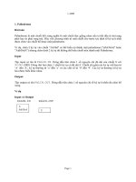
COMMENTARY AND RECOMMENDATIONS ON 17.3. It is
recommended that the sign shown in Figure 1 be
used to indicate the location of manual controls.
Manual controls for systems should be located in an
accessible place sufficiently removed from the
hazard to permit them to be safely operated in
emergency, yet close enough for the operator to be
aware of conditions at the hazard.
Licensed copy:RMJM, 30/08/2005, Uncontrolled Copy, © BSI
17.4 Automatically operated systems
Automatic systems shall incorporate a manually
operated lock-off device which will prevent
discharge of the system, but will not prevent the
giving of the alarm signal. Operation of the lock-off
device shall be indicated at the plant or fire control
centre.
COMMENTARY AND RECOMMENDATIONS ON 17.4. The
lock-off device is for use when maintenance
personnel are working on the system.
To allow personnel to evacuate from the protected
area prior to discharge of foam a time delay may be
incorporated in the automatic system. The delay
period will depend upon the potential speed of fire
spread and the means of escape from the protected
area, but it should not normally exceed 60 s.
12
Where time delays are incorporated in the system,
the system may also be equipped with a biased
switch, located within the protected area, the
manual operation of which at any time during the
delay period will prevent foam discharge until
release of the switch.
17.5 Detection and alarm equipment
Automatic detection and control equipment shall
give a positive warning of any fault or abnormality,
e.g. loss of power or pressure which may render the
detection and control system inoperative.
Automatic detection equipment shall provide a local
alarm at the control point of each automatic system,
as well as at the plant or central control point.
COMMENTARY AND RECOMMENDATIONS ON 17.5.
Automatic systems should include a facility for
coincidental shutdown of any heat source or
potential means of ignition or reignition in the
vicinity of the hazard. Detection and alarm
equipment may be electrical, pneumatic, hydraulic
or mechanical, e.g. link line type. Automatic
detection and control equipment should comply with
the appropriate recommendations of BS 5839-1.
Detectors should comply with the requirements of the
appropriate Part of BS 5445 or BS 5839.
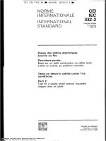
17.6 Warning signs
The warning sign shown in Figure 2(a)
or Figure 2(b) as appropriate shall be displayed at
the entrances to enclosed areas or compartments
protected by an automatic medium or high
expansion foam system.
© BSI 02-1999
Licensed copy:RMJM, 30/08/2005, Uncontrolled Copy, © BSI
BS 5306-6.2:1989
Figure 1 — Sign for display at manual control
© BSI 02-1999
13
© BSI 02-1999
Licensed copy:RMJM, 30/08/2005, Uncontrolled Copy, © BSI
BS 5306-6.2:1989
14
Section 1
Figure 2 — Signs for display at entrances to hazard
BS 5306:1989
15
Licensed copy:RMJM, 30/08/2005, Uncontrolled Copy, © BSI
Section 1
© BSI 02-1999
Figure 2 — Signs for display at entrances to hazard (concluded)
BS 5306-6.2:1989
Section 5. Specific types of system
18.3 Duration of discharge
18.1 General
Licensed copy:RMJM, 30/08/2005, Uncontrolled Copy, © BSI
18 Medium expansion foam systems
The minimum duration of discharge of systems
discharging at the minimum rate specified in 18.2
shall be as given in Table 1. The minimum duration
of systems discharging at higher than the minimum
rate may be reduced in proportion but shall be not
less than 70 % of the time given in
Table 1.
Table 1 — Minimum discharge times for
medium expansion foam systems
discharging at the minimum rate
Medium expansion foam systems shall comply
with 18.2 to 18.4. The requirements are applicable
to systems for protection against fires in
a) flammable liquid as spills of average depth not
more than 25 mm; or
b) flammable liquids in defined areas such as
bunds and heat treatment baths; or
c) combustible solids where up to about 3 m foam
build-up is necessary to cover the hazard,
e.g. engine test cells and generating sets.
COMMENTARY AND RECOMMENDATIONS ON 18.1. The
following features should be considered in the design
of systems.
a) Because of the low density of the foam it can be
applied gently to flammable liquids.
b) A high rate of foam build-up is possible and it
is particularly of advantage with combustible
solids.
c) Medium expansion foam may have a relatively
low stability and burn back resistance, and it
achieves its results by rapid application. It is
essential that the application rate is adequate to
meet any likely contingency.
d) Foam distribution may be adversely affected by
wind. In outdoor hazards, the foam should be
applied, wherever possible, to protected areas, and
allowance should always be made for likely losses
due to wind speeds above 10 m/s.
e) Medium expansion foam should not be used to
protect hazards involving unenclosed energized
electrical equipment, unless the equipment can be
switched off before actuation of the system.
f) It may be necessary to screen foam-makers to
prevent obstruction, including obstruction by
birds or animals.
18.2 Application rate
18.2.1 Flammable liquids. The application rate,
determined in accordance with Appendix B, shall be
not less than:
a) the rate, agreed with the user, shown to be
effective by tests; or
b) if test data is not available:
4 L/m2 for hydrocarbon liquids, or
6.5 L/m2 per minute for foam destructive
liquids.
18.2.2 Combustible solids. The application rate,
determined in accordance with Appendix B, shall be
not less than the rate agreed with the user.
16
Hazard
Minimum
discharge
time
min
Indoor and outdoor spill up to 100 m2 10
Other indoor hazards and outdoor
protection
15
18.4 Quantity of foam concentrate
18.4.1 The quantity of foam concentrate or premix
available for immediate use in the system shall be
not less than:
V
A×R×C×T
= --------------------------------------100
or
V1 = A × R × T
where
V1 is the minimum quantity of premix (in L);
V is the minimum quantity of foam concentrate
(in L);
A is the area of application (in m2);
R is the rate of application of foam solution
(in L/m2 per minute);
C is the concentration (in %);
T is the duration of application (in min);
plus a quantity not less than the allowance specified
in 18.4.3.
18.4.2 The hazard requiring the greatest quantity of
foam concentrate shall be used to determine the
quantity available for immediate use.
18.4.3 Allowance shall be made for the quantity of
foam concentrate needed to fill the feed lines
installed between the source and the most remote
monitor or branchpipe.
© BSI 02-1999
BS 5306-6.2:1989
19 High expansion foam systems
Licensed copy:RMJM, 30/08/2005, Uncontrolled Copy, © BSI
19.1 General
High expansion foam systems shall comply
with 19.2 to 19.7. The requirements are applicable
to total flooding systems, local application systems
and portable or mobile units used as adjuncts to
fixed systems, and fed from them.
COMMENTARY AND RECOMMENDATIONS ON 19.1. High
expansion foam systems are used for the total
flooding of warehouses, aircraft hangars, furniture
depositories and other similar large volumes. This
type of system can also be used in situations where it
would be hazardous to send personnel, for example,
into underground enclosures such as refrigerated
rooms, mine shafts or cable tunnels, where smoke
logging could occur and in consequence exit routes
might be difficult to find.
Local application systems are used for smaller
enclosures within larger areas, e.g. pits, basements,
under-floor cavities, engine test cells and enclosed
generating sets, where volume filling would be an
effective means of dealing with an inaccessible fire
situation. Local application systems may be used
both indoors and outdoors provided there is a means
of containing the foam and shielding it from the
effects of wind on the foam-making devices and on
the foam distribution.
Portable or mobile units are used as an adjunct to a
fixed system where the nature of the hazard is
variable, or some of it falls outside the main
protected area.
The following features should be considered in the
design of systems.
a) High expansion foam is suitable for a wide
range of solid and liquid fires although the
expansion used may have some effect on the
efficiency of the foam in extinguishing any
particular fire.
b) It is effective on flammable liquid fires
involving hydrocarbon liquids, including
cryogenic liquids.
c) The smothering effect of high expansion foam
retains the combustion gases in close proximity to
the fire and restricts the ingress of air.
d) The production of steam from the expanded
foam dilutes the oxygen concentration in the area
of the fire and also extracts latent heat which
helps to cool the fire.
e) The breakdown of the foam solution can also
produce a damping-down of combustible solids,
and cooling or dilution of the surface layers of
some flammable liquids below their fire point.
© BSI 02-1999
f) Air for making foam should be clean and it is
essential that it is not contaminated by
combustion products, which can cause rapid
breakdown of the foam. In general air from
outside the protected enclosure should be used to
make foam; this will reduce the possibility of
contamination.
g) It is essential to make allowance for the limits
to the distance that foam can be made to travel,
when deciding the number and position of high
expansion foam generators.
h) In outdoor locations, foam distribution may be
adversely affected by wind. Allowance for this has
to be made in calculation of foam application
rates and quantities.
i) Deep-seated fires in combustible solids may not
be extinguished immediately, and cooling may
require the maintenance of foam cover for
considerable periods of time.
j) High expansion foam should not be used on
chemicals which release sufficient oxygen to
sustain combustion, e.g. cellulose nitrate.
19.2 Venting
19.2.1 General. Where air from outside the
protected enclosure is used to make the foam,
provision shall be made for the venting of air and/or
products of combustion displaced from the enclosure
by the discharged foam.
19.2.2 Vent design. The vent(s) shall be positioned
at the most remote point(s) from the foam inlet(s),
and shall be to the open air. The vent(s) shall be of
open design, or it normally closed shall open
automatically on actuation of the system.
COMMENTARY AND RECOMMENDATIONS ON 19.2.
Correct positioning of the vent(s) is necessary to
ensure that the submergence depth is achieved
throughout the protected area. Venting is to the
outside air to allow the safe dispersal of smoke and
combustion products.
The area of the vent(s) should be sufficient to limit
the venting velocity to not more than 300 m/min.
This will be achieved if the vent area (in m2) is not
less than F/300, where F is the foam discharge rate
in m3/min.
Venting is not usually necessary where air from
within the enclosure is used to make the foam.
19.3 Submergence depth
The system shall produce, throughout the protected
area, a depth of foam sufficient to cover and
extinguish the highest hazard.
COMMENTARY AND RECOMMENDATIONS ON 19.3. In
unsprinklered enclosures of combustible
construction the submergence depth should be
sufficient to fill the enclosure.
17
BS 5306-6.2:1989
For combustible solids, in enclosures which are
sprinklered or are of non-combustible construction
the submergence depth should be sufficient to cover
the highest hazard with
1 m, or
0.1 times the height of the highest hazard, in
metres,
whichever is the greater, of foam.
For flammable liquids the submergence depth
should be determined by test, and may be
considerably more than for combustible solids.
Licensed copy:RMJM, 30/08/2005, Uncontrolled Copy, © BSI
19.4 Submergence time
The system shall produce throughout the protected
area a depth of foam not less than the submergence
depth in not more than the appropriate maximum
time given in Table 2.
COMMENTARY AND RECOMMENDATIONS ON 19.4. The
principle involved is that the enclosure to be
protected should be filled to the submergence depth
with high expansion foam, before an unacceptable
degree of fire damage occurs. Allowance should be
made for uneven depth across the protected area
since the foam is stiff and does not flow readily. In
general, the depth will be least at the furthest
distance from the generator, but this will be modified
by the presence of obstructions, vents and leakages,
and by the interaction of a number of generators
filling the protected enclosure. Where sprinkler
protection is used a longer submergence time applies
(see Table 2) but some additional breakdown of foam
will result.
In calculating the foam application rate, the volume
of vessels, machinery or other permanently located
equipment may be deducted from the total volume to
be protected. Volumes occupied by stored materials
are not deducted from the volume of the area to be
protected, since the quantity may vary with time.
Provided appropriate attention is given to
distribution [see 19.1 g)], the requirements for
submergence time will be met if the discharge rate of
the system is not less than:
( D × A ) – V eq
F = C N × C L × F S + ------------------------------------T
where
D is the submergence depth (in m);
F is the foam discharge rate (in m3/min);
T is the submergence time (in min);
discharge (in m3/min). The factor should be
determined either by test or, in the absence of
specific test data by the following formula:
Fs = 0.075 × Q
where
Q is the estimated total discharge from the
maximum number of sprinklers expected to
operate (in L/min).
19.5 Quantity of foam concentrate
The quantity of foam concentrate (in litres)
available for immediate use in the system shall be
not less than:
a) for fire involving combustible solids:
250 × FC ; or
-------E
b) for fires involving flammable liquids:
150 × FC
-------E
where
F is the foam discharge rate (in m3/min)
(see commentary and recommendations
on 19.4);
C is the concentration (in %);
E is the expansion.
COMMENTARY AND RECOMMENDATIONS ON 19.5.
The
quantities specified allow system running times
(whether continuously or intermittently) of 25 min
for combustible solids and 15 min for flammable
liquids. For flammable liquids it is usual for the
system to run continuously but for systems protecting
combustible solids once submergence is achieved it is
usual to run the system intermittently, in effect
discharging foam at a rate equivalent to the
breakdown rate, to maintain the submergence depth
for the maximum time possible.
19.6 Personnel safety
2
A is the floor area of the protected space (in m );
Veq is the volume of any permanently installed
equipment, vessels or machinery, excluding the
volume of any removable stored material or
equipment (in m3).
18
CN = 1.20, an empirical factor based on the
average reduction in foam quantity due to
solution drainage, fire, wetting of dry surfaces,
etc.
CL = 1.1 an empirical factor compensating for the
loss of foam due to leakage around doors and
windows where these are closed but not sealed.
Fs is the rate of foam breakdown by sprinkler
Unenclosed electrical apparatus shall be switched
off when the foam system is activated. Total
immersion of personnel in the foam shall be avoided
where possible.
© BSI 02-1999
BS 5306-6.2:1989
Table 2 — Maximum submergence times for high expansion foam systems
Hazards
Maximum submergence times
High expansion
foam only
High expansion foam
with supporting water
sprinklers
min
min
2
3
Flammable liquids with flash points above 40 °C
3
4
Low density combustible solids, e.g. foam rubber, foam plastics,
rolled tissue or crepe paper
3
4
High density combustible solids, e.g. rolled paper, rubber tyres
Licensed copy:RMJM, 30/08/2005, Uncontrolled Copy, © BSI
Flammable liquids with flash points not above 40 °C
7
COMMENTARY AND RECOMMENDATIONS ON 19.6.
Since total immersion in high expansion foam
presents a considerable hazard to life, personnel
working in areas covered by the system should be
given adequate warning to allow them to evacuate
the area before flooding with foam commences
(see 17.4 and 17.6).
Instructions should be given that should anyone
inadvertently become immersed in high expansion
foam the nose and mouth should be covered with the
hand or preferably a cloth, e.g. a handkerchief, to
minimize the discomfort in breathing. It should be
emphasized that where a considerable depth of foam
exists, the foregoing may not be sufficient to ensure
that foam does not enter the nose and mouth.
Immersion in foam can cause irritation to eyes and
breathing passages, make it impossible to see or hear
and produce a stifling feeling because of the
insulation effect. It could readily result in
claustrophobia and panic.
© BSI 02-1999
5
Where trained personnel need to enter the foam for
rescue or firefighting, self-contained breathing
apparatus should be used in conjunction with a life
line. Canister-type gas masks react with the water
and foam and it is therefore essential that these
should not be used.
19.7 Clearance of high expansion foam
Provision shall be made for the clearance of foam
from the hazard area.
COMMENTARY AND RECOMMENDATIONS ON 19.7. After
fire extinction, foam may be cleared from a building
by encouraging as much ventilation as possible with
forced draughts or the use of all openings. A water
spray may be used to cut a path through the foam
and this is most effective when employed an hour or
more after foam application. Dry powders and
special defoaming chemicals are also effective in
destroying high expansion foam.
19
BS 5306-6.2:1989
Appendix A Classification of foam
concentrates
Licensed copy:RMJM, 30/08/2005, Uncontrolled Copy, © BSI
NOTE Foam concentrates are liquids, usually aqueous
solutions, which are mixed with water to produce the foam
solution used to make foam.
Foam concentrates are generally classified by composition, and
for the purposes of this standard as described in this appendix
(see 15.1).
A.1 Protein
Protein (P) foam concentrates are aqueous solutions
of hydrolized protein and are generally used at 3 %
and 6 % concentration.
A.2 Fluoroprotein
Fluoroprotein (FP) foam concentrates are protein
foam concentrates with added fluorinated surface
active agents. The foam is generally more fluid than
protein foam, gives faster control and extinction of
the fire, and has a greater ability to reseal if the
foam blanket is disturbed. Fluoroprotein foam is
more resistant than protein foam to contamination
by hydrocarbon liquids and is generally used at 3 %
or 6 % concentration.
A.3 Film-forming fluoroprotein
Film-forming fluoroprotein (FFFP) foam
concentrates are protein foam concentrates with
added fluorinated surface active agents. The foam is
more fluid than both protein and standard
fluoroprotein foams. The foam is resistant to
contamination by hydrocarbon liquids. The solution
is film-forming on some liquid hydrocarbon fuel
surfaces and is generally used at 3 % or 6 %
concentration.
A.4 Synthetic
Synthetic (S) foam concentrates are solutions of
hydrocarbon surface active agents. Fluorinated
surface active agents if present are present in
amounts which do not lead to film-forming on
hydrocarbon liquids. Synthetic foam concentrates
are generally used at a concentration between 1 %
and 6 %.
A.5 Aqueous film-forming
Aqueous film-forming (AFFF) foam concentrates
are generally based upon mixtures of hydrocarbon
and fluorinated hydrocarbon surface active agents.
Foam solutions made from fluorochemical
concentrates are film forming on some liquid
hydrocarbon fuel surfaces and are generally used
at 1 %, 3 % or 6 % concentration.
A.6 Alcohol resistant
Alcohol resistant (AR) foam concentrates are
formulated for use on foam destructive liquids; the
foams produced are more resistant than ordinary
foams to breakdown by the liquid. They may be of
any of the classes given in A.1 to A.5 and may be
used on fires of hydrocarbon liquids with a fire
performance generally corresponding to that of the
parent type. Film-forming foams do not form films
on water miscible liquids. Alcohol resistant foam
concentrates are generally used at 6 %
concentration on water miscible fuels.
Appendix B Determination of
application rate (medium expansion)
and foam discharge rate (high
expansion)
NOTE
See 18.2 and 19.4.
B.1 Apparatus
B.1.1 Pressure gauge, installed adjacent to the
discharge point in the hydraulically most remote
location, with respect to the main foam solution
supply line to the system.
B.2 Procedure
Discharge the system and record the steady state
discharge pressure (P) at the nozzle. Visually
examine all discharge points to see that they are
operating satisfactorily. Sample the foam from the
most remote nozzle to measure expansion and
drainage in accordance with Appendix C.
B.3 Calculation
B.3.1 Medium expansion foam
Calculate the overall foam solution flow rate (Q)
(in L/min) where only one type of nozzle is used from
the equation:
Q = N × K × P 0.5
where
Q is the foam solution flow rate (in L/min);
K is the nozzle discharge coefficient;
N is the number of nozzles fitted;
P is the steady state nozzle pressure (in bar);
or where more than one type of nozzle is fitted, from
the sum of the overall rates for each type of nozzle,
given by the equation:
n
0.5
Q = C N× K × P
where
n is the number of types of nozzle.
Calculate the application rate R (in L/m2 per
minute) from the equation:
Q
R = --A
20
© BSI 02-1999
BS 5306-6.2:1989
where
2
A is the area covered by the system (in mm ).
NOTE The discharge coefficients are determined by separate
tests of the nozzles concerned measuring flow rates over the
pressure range involved.
B.3.2 High expansion foam
Calculate the foam solution flow rate in accordance
with B.3.1.
Calculate the foam discharge rate (in m3) from:
F=Q×E
where
E is the expansion, determined in accordance
with Appendix C.
Appendix C Determination of
expansion
Licensed copy:RMJM, 30/08/2005, Uncontrolled Copy, © BSI
NOTE
See clause 13.
C.1 Apparatus
C.1.1 Cylindrical aluminium container, of
volume 166.25 L, internal diameter 500 mm and
height 847 mm.
C.1.2 Balance, preferably with digital readout.
C.1.3 Stand, to support the container vertically.
C.2 Procedure
Carry out the procedure as follows.
a) Weigh the empty pan (W1).
b) Collect a sample of foam, directly into the
container. Collect the sample either from the
foam outlet and as close as possible to the point at
which the foam would be applied to the fuel or
from a foam sampling point in the system as close
as possible to the outlet.
c) As soon as the container is full skim the foam
from above the level of the rim and remove any
foam adhering to the outside.
d) Weigh with the contained liquid and foam
(W2).
C.3 Calculation
Calculate the foam expansion E from the equation:
E
166.25
= -------------------------W2 – W1
The volume of foam is the volume of the
pan, 166.25 L, and W2 – W1 is the volume of water
(equal to the mass of the foam) contained in it.
Appendix D Determination of
percentage concentration
NOTE
See 15.1.
D.1 Method 1
D.1.1 Apparatus
D.1.1.1 Three graduated cylinders, of 100 mL
capacity.
D.1.1.2 Measuring pipette, of 10 mL capacity.
D.1.1.3 Beaker, of 100 mL capacity.
D.1.1.4 Beaker, of 500 mL capacity.
D.1.1.5 Refractometer, having a measuring range
of 1.3330 to 1.3723 index of refraction (equivalent
to 0 % to 25 % sugar content in water).
D.1.2 Procedure
Prepare a calibration curve of refractive index
against foam concentrate content (V/V), using the
specified concentrate and typical sample of the
water to be used in the system.
NOTE The concentrations used should cover a range from
about 0.5 times to 2 times the specified concentration. For
example, to prepare a calibration curve for a 6 % solution, place
three measured volumes of about 3 mL, 6 mL and 9 mL in each
of the 100 mL graduated cylinders and make up to 100 mL by
filling gently with the actual supply water.
After gentle but thorough stirring, take a refractive index
measurement for each sample and prepare a calibration curve.
Samples of the foam drained out in the drainage test should now
be used to estimate the refractive index and from this, the
concentration.
D.2 Method 2
Determine the percentage concentration directly by
measuring the rate of withdrawal of foam
concentrate from the tank (e.g. by rate of reduction
of level) and the rate of flow of water at a suitable
point, either by pressure loss across an orifice plate
or by a direct reading flowmeter.
NOTE In field determinations the choice of method of
measuring the foam induced and the water flow will depend upon
the design of the system and the available measuring points. This
test method will need to be decided at the design stage and
allowed for in the equipment and fittings supplied to the
installation.
where
W1 is the mass of the empty pan (in kg);
W2 is the mass of the full pan (in kg).
© BSI 02-1999
21