pc connection programmable terminal operation manual
Bạn đang xem bản rút gọn của tài liệu. Xem và tải ngay bản đầy đủ của tài liệu tại đây (565.49 KB, 69 trang )
PC CONNECTION
Programmable Terminal
Operation Manual
Produced March 1999
OMRON Product References
All OMRON products are capitalized in this manual. The word “Unit” is also capitalized when it refers to an
OMRON product, regardless of whether or not it appears in the proper name of the product.
The abbreviation “Ch,” which appears in some displays and on some OMRON products, often means
“word” and is abbreviated “Wd” in documentation in this sense.
The abbreviation “PC” means Programmable Controller and is not used as an abbreviation for anything
else.
Visual Aids
The following headings appear in the left column of the manual to help you locate different types of infor-
mation.
Note
Indicates information of particular interest for efficient and convenient operation
of the product.
1, 2, 3
1. Indicates lists of one sort or another, such as procedures, checklists, etc.
Names of Devices and Tools
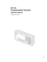
PT
Refers to an OMRON NT series programmable terminal.
PC
Refers to a Mitsubishi A series or FX series programmable controller.
System installer
Refers to an OMRON NT series system installer.
PT Type Model Applicable PC Personal Computer
NT31/NT31C
Attached to the sup-
port tool (*1)
Mitsubishi A series
Mitsubishi FX series
For IBM PC/AT com-
patibles
NT631/NT631C
Attached to the sup-
port tool (*1)
Mitsubishi A series
Mitsubishi FX series
For IBM PC/AT com-
patibles
(*1) System program for NT31/NT31C and NT631/NT631C is attached to
“NT Series Support Tool for Windows 95/98 (Ver. 3.0)”.
OMRON, 1999
!
! "
! "!
#$ % &
! #
$
%
" %
& ' ! (
'
! ( '&
! #
)
"
" "%
) &'
)
Related Manuals and Their Contents:
The related manuals are indicated below.
The * symbol at the end of the manual number is the revision history symbol.
[Connections between the programmable terminal (PT) and programmable controllers (PC), etc.]
PC Connection, Operation Manual V042-E1-
This Operation manual describes how to connect the programmable terminal
(PT) to programmable controllers (PC) and other equipment, and how to make
the settings required for these connections.
[For information on NT series PT functions, operations, and restrictions]
NT31/31C Programmable Terminal Operation Manual V043-E1-
NT631/631C Programmable Terminal Operation Manual V044-E1-
These manuals contain full descriptions of NT series PT functions, operations,
and restrictions.
NT Series Support Tool for Windows 95/98 (Ver. 3.0) Operation
Manual V053-E1-
The screens displayed in the PT are created and transferred with the support
tool. This manual describes how to create and transfer the screen data. It de-
scribes also how to usethe system installer for installing the system programto
the PT.
How to Use the Manual
This Operation Manual comprises the following Sections.
SECTION 1 Connectable Hardware Combinations
This section describes the combinations of PT and programmable controller that
can be connected.
This section also describes the types of system program and system installer re-
quired for connection with a PC produced by the other manufacturers to opera-
tion of such a PC, and the types of usable support tools.
SECTION 2 Use with Mitsubishi A Series Computer Link Systems
This section describes how to make the connections and settings when a PT is
connected to a Mitsubishi A series programmable controller in a computer link
system.
This section also describes the combinations of PTs and programmable control-
lers that can be connected, the connection method of cables, the settings re-
quired for operation, and the specific errors that may occur when using the PT in
a computer link system that uses a Mitsubishi A series programmable controller.
SECTION 3 Use with Mitsubishi FX
This section describes how to make the connections and settings when a PT is
connected to a Mitsubishi FX series programmable controller.
This section also describes primarily the combinations of PTs and programmable
controllers that can be connected, the connection method of cables, and the set-
tings required for operation.
Appendix
This section describes the differences of the PT functions depending on the con-
nected host and the specifications of the connectors of OMRON products used
for communications.
! * !
WARNING
WARNING
Caution
1 Intended Audience
This manual is intended for the following personnel, who must also have knowl-
edge of electrical systems (an electrical engineer or the equivalent).
Personnel in charge of installing FA systems.
Personnel in charge of designing FA systems.
Personnel in charge of managing FA systems and facilities.
2 General Precautions
The user must operate the product according to the performance specifications
described in the operation manuals.
Before using the product under conditions which are not described in the manual
or applying the product to nuclear control systems, railroad systems, aviation
systems, vehicles, combustion systems, medical equipment, amusement ma-
chines, safety equipment, and other systems, machines, and equipment that
may have a serious influence on lives and property if used improperly, consult
your OMRON representative.
Make sure that the ratings and preformance characteristics of the product are
sufficient for the systems, machines, and equipment, and be sure to provide the
systems, machines, and equipment with double safety mechanisms.
This manual provides information for using the Programmable Terminal. Be sure
to read this manual before attempting to use the software and keep this manual
close at hand for reference during operation.
It is extremely important that Programmable Terminals related devices be used
for the specified purpose and under the specified conditions, especially in ap-
plications that can directly or indirectly affect human life. You must consult with
your OMRON representative before applying Programmable Terminals to the
abovementioned applications.
Do not use input functions such as PT touch swiches for applications where dan-
ger to human life or serious damage is possible, or for emergency switch applica-
tions.
3 Safety Precautions
In order to use this product safely and correctly, you must read and fully under-
stand the “Safety Precautions” inthe NT series Operation Manual before using it.
After connecting a communication cable, always secure it with the screws.
Otherwise the cable may disconnect, causing operation to fail.
Terminology
BCD (binary coded decimal)
The value is stored as a decimal number instead of as a hexadecimal number by using only 0 to 9 of the
hexadecimal numbers (0 to F). By using the decimal representation, the conversion of decimal numbers
becomes easy.
For example, when decimal “1234” is to be stored to the channel, it is usually required to be converted to
the hexadecimal “04D2”, because the channel is hexadecimal. When using BCD, decimal “1234” isstored
as “1234” to the channel.
Counter (C)
Area used by a Mitsubishi PC.
Word device to be used for storing the present value of the counter used for program.
Output relay (Y)
Area used by a Mitsubishi PC.
Bit device connected to an actual output contact. As the case may be, output bits of the specific function
module is allocated.
State (S)
Area used by a Mitsubishi PC.
Bit device primarily used for status of processing when using step ladder command or as an annunciator.
Contact
Term for the PLC made by OMRON indicating the minimum unit of I/O. It is set to ON or OFF.
Timer (T)
Area used by a Mitsubishi PC.
Word device to be used for storing the present value of the timer used for program.
Direct access
Connection method in which word bits on a PC and a memory table, lamp, or touch switch correspond
one-to-one, and memory contents are automatically updated to reflect any change in one side directly to
another.
For example, if bits onaPC corresponding to a PT lamp are turned on, thePT lamp will lightup.Ifavalueis
written to words on the PC corresponding to a PT value memory table, the same value data is written to
the corresponding value memory table.
It is possible to control a PT from a PC without transmitting the command from the PC to the PT allowing
rapid communication between the PC and PT by decreasing tasks at the PC side.
Channel (CH)
Term for the PLC made by OMRON. I/O unit for 16 “contacts”. It may expressed as “CH”.
Communication speed (bps)
Data amount possible to be sent and received during period of time. “Bps” is a abbreviation for “bits per
second” and refers to the number of bits sent or received in 1 sec.
Data register (D)
Area used by a Mitsubishi PC.
Word device to be used for storing values or words.
In D8000 and higher, it has a specific function for the operation of a PC.
Input relay (X)
Area used by a Mitsubishi PC.
Bit device connected to an actual input contact. As the case may be, input bits of the specific function
module are allocated.
Bit
Term for information processing, such as computer, and refers to the minimum unit of data. It can be set to
two values, “0” or “1”. In PCs made by Mitsubishi, “contact” is expressed by “bit”. “0” and “1” correspond to
“OFF” and “ON”, respectively.
Bit device
Area in Mitsubishi PC for reading and writing primarily by bits.
There are four types of bit devices usable in the PT.
M (auxiliary relay)
S (state)
X (input relay)
Y (output relay)
Auxiliary relay (M)
Area used by a Mitsubishi PC.
Bit device which cannot be connected to an I/O contact, but can be used as I/O in programs.
In M8000 and higher, there are specific functions for the operation of a PC.
Memory switch
Performs setting related to the PT operation. This is not an actual switch like a DIP switch, but a switch
electrically memorized inside the PT.
It can be set via a “memory switch” of the “maintenance mode” in the PT.
Memory table
Memory inside the PT the user can use for displaying data in the PT. There are two memory tables: the
value memory table for storing values and the word memory table for storing words.
Word
Term for information processing, such as computer, and refers to a unit corresponding to “channel”. 16
bits corresponds to 1 word.
In a Mitsubishi PC, “channel” is expressed as “word”.
Word device
Area in a Mitsubishi PC primarily read by words.
There are three types of word devices usable in the PT:
D (data register)
T(timer)
C (counter)
! + !
+ ,
! "
Section1 1
1-1 Possible Combinations
The table below shows the combinations that can be connected.
PT Type Model Connector Connection to Mitsubishi
A (Computer Link)
Connection to
Mitsubishi FX
RS-232C RS-422A
Mitsubishi FX
NT31/NT31C NT31-ST121
-EV1
RS-232C
"
NT31/NT31C
(*1)
NT31-ST121
-EV1
NT31C-ST141
-EV1
RS-422A
"
NT631/NT631C
NT631-ST211
-EV1
RS-232C
"
NT631/NT631C
(*1)
NT631C-ST141
-EV1
NT631C-ST151
-EV1
RS-422A
"
: Direct connection
- : Via RS-232C/RS-422A convertor unit
(*1) In order to use NT31/NT31C, NT631S/NT631C in multi-vendor systems, a
dedicated system program must be installed in the PT using the “NT series
system installer”.
Section1 2
1-2 Installing the System Program
In order to use an NT31/NT31C or NT631/NT631C in a multi-vendor system, a
dedicated system program must be installed inthe PT using the “NT series system
installer” shown in the table below.
PT Type Model Applicable PC Personal Computer
NT31/NT31C
Attached to the sup-
port tool (*1)
Mitsubishi A series
Mitsubishi FX series
For IBM PC/AT com-
patibles
NT631/NT631C
Attached to the sup-
port tool (*1)
Mitsubishi A series
Mitsubishi FX series
For IBM PC/AT com-
patibles
(*1) System program for NT31/NT31C and NT631/NT631C is attached to
“NT Series Support Tool for Windows 95/98 (Ver. 3.0)” (NT-ZJ3MX1/NT-
ZJ3MX1-EV3).
For details on how to operate the system installer, refer to its instruction manual, or
the PT Operation manual.
Section1 3
1-3 Usable Support Tools
When using the PT in a multi-vendor system, one of the following support tools
must be used.
Model Hardware Requirement
NT-ZJ3MX1-EV3
NT-ZJCMX1-EV3
For IBM PC/AT compatibles
The programmable controllers (PC) that can be connected to the PT are deter-
mined by the “PLC Vendor” data set in the screen data memory board. According-
ly, screen data complying with the programmable controller to be connected must
be transferred to the PT in advance.
The “PLC Vendor” is set with the support tool. The applicable programmable con-
trollers (PCs) depending on the “PLC Vendor” setting are as follows.
PLC Vendor Applicable Programmable Controller (PLC)
OMRON For connection to an OMRON CS1 series, C series, or
CVM1/CV series PLC
Mitsubishi A For connection to a Mitsubishi Electric MELSEC A series
PC
Mitsubishi FX For connection to a Mitsubishi Electric MELSEC FX series
PC
Memory link (MEMLINK) For a memory link connection with NT31/NT31C or
NT631/NT631C
!" #" $ %
! + . + ! /
.
! #
$
%
" %
& ' ! (
Section 2 1
2-1 Usable PTs and PCs
The PT, PC, and computer link module models that can be used in a computer link
system that uses Mitsubishi A series PCs are indicated here.
Usable PT Models
The PT models that can be used with a computer link system that uses Mitsubishi
A series PCs are tabled below.
When using NT31/NT31C, NT631/NT631C, install the system program for Mitsu-
bishi A computer links in advance with the “NT series system installer”.
PT Type Model
NT31 NT31-ST121
-EV1
NT31C NT31C-ST141
-EV1
NT631 NT631-ST211
-EV1
NT631C NT631C-ST141
-EV1
NT631C-ST151
-EV1
Reference:
For details on the direct connection function, refer to the Operation manual for the
PT model used.
Section 2 1
Modules Mounted at the Connected PC
Connections to a Mitsubishi A series PC are made at a computer link module. The
table below lists the computer link modules to which the connection can be made
with each type of connector.
Computer Link Module Used
Series CPU Module
RS-232C RS-422
A0J2H A0J2HCPU A0J2-C214S1
A1SH
A1SJH
A2SH
A2US
A2US-S1
A2USH-S1
A1SHCPU
A1SJHCPU
A2SHCPU
A2USCPU
A2USCPU-S1
A2USHCPU-S1
A1SJ71UC24-R2 A1SJ71UC24-R4
A1N
A2N
A2N-S1
A3N
A2A
A2A-S1
A3A
A2U
A2U-S1
A3U
A1NCPU
A2NCPU
A2NCPU-S1
A3NCPU
A2ACPU
A2ACPU-S1
A3ACPU
A2UCPU
A2UCPU-S1
A3UCPU
AJ71UC24
Section 2 2
2-2 Connection
This section describes the methods for connection between the PT and the com-
puter link module.
Make cables that are suitable for the conditions of use, following the wiring details
given in this section.
The communication connector (terminal block) of each device is as follows:
- NT31/NT31C
Serial port A (RS-232C dedicated connector)
Serial port B (switching RS-232C/RS-422A/485 connectors)
- NT631/NT631C
Serial port A (RS-232C dedicated connector)
Serial port B (switching RS-232C connector and RS-422A/485 terminal
blocks)
- Computer link module
RS-232C connector or RS-422A terminal block
Section 2 2
Parts Required for Connection
The connectors, connector covers, crimp terminals, and recommended cables for
use with OMRON products are described here.
For details on the connectors, connector covers, and crimp terminals used at the
computer link module side, refer to the manual for the computer link module.
Parts for RS-232C (Common to PT and NT-AL001)
Part Model Remarks
Connector XM2A-0901 9-pin type, made by OMRON
XM2A-2501 25-pin type, made by OMRON
DE-9P 9-pin type, made by JAE
Connector cover XM2S-0911 9-pin type, made by OMRON
XM2S-2511 25-pin type, made by OMRON
DE-CI-J6 9-pin type, made by JAE
Cable
AWG28
5P
IFVV-SB
Multi-core shielded cable, made
by Fujikura, Ltd
CO-MA-VV-SB
5P
28AWG
Multi-core shielded cable, made
by Hitachi Cable, Ltd
Recommended Parts for RS-422A Terminal Block (For NT631/NT631C)
<Appropriate crimp terminals>
Fork type Round type
6.2 mm or less 6.2 mm or less
Part Model Remarks
Crimp terminal
(M3.5)
2-YS3A Fork type, made by Japan Sold-
erless Terminal MFG
(M3.5)
2-YAS3.5 Fork type, made by Fuji Terminal
2Y-3.5 Fork type, made by Nichifu Ter-
minal
2-3.5 Round type, made by Japan
Solderless Terminal MFG
V2-S3.5 Round type, made by Fuji Termi-
nal
2-3.5 Round type, made by Nichifu
Terminal
Cable H-9293A
(CO-HC-ESV-3P
7/0.2)
Made by Hirakawa Hewtech
corp.
Section 2 2
Recommended Parts for RS-422A Terminal Blocks (For NT-
AL001)
<Appropriate crimp terminals>
Fork type Round type
6.2 mm or less 6.2 mm or less
Part Model Remarks
Crimp terminal Y1.25-3.5L Fork type, made by molex
(M3)
(*1)
1.25-N3A Fork type, made by Japan Sold-
erless Terminal MFG
(*1) Appropriate wire size: 0.3 to 0.75 mm
2
Connection Between RS-232C (PT) and RS-232C (Computer Link)
At the PT side, make connections using the following communication ports.
- NT31/NT31C, NT631/NT631C serial port A (dedicated to RS 232C) or serial
port B (RS 232C)
PT
25-pin connector/
9-pin connector
Mitsubishi A series PC
Computer link module
Cable with RS-232C connector
(maximum length: 15 m)
(RS-232C)
25-pin/9-pin
connector
Notice:
After connecting a communication cable, always secure it with the screws.
When connectiong to a terminal block, always use crimp terminals.
Section 2 2
Wiring When Computer Link Module has a 25-pin Connector
There is a shielding wire at the computer link module side only: connect it to the
connector cover and to the No.1 pin (FG).
1
2
3
4
5
6
7
8
9
FG
RD
RS
CS
+5V
SG
Shielding wire
PT
1
2
3
4
5
6
7
8
20
FG
SD
RD
RS
CS
DR
SG
CD
ER
(25-pin)
SD
(9-pin)
Mitsubishi computer link module
RS-232C
interface
Pin No.Abbrev. Pin No. Abbrev.
RS-232C
interface
Connector
cover
When using NT31/31C serial port B
1
2
3
4
5
6
7
8
Pin No.Abbrev.
FG
RD
RS
CS
SG
RS-232C
/422A
485
interface
Shielding wire
NT31/NT31C side
RS-232C
interface
2
3
4
5
6
7
8
20
(25-pin)
Pin No. Abbrev.
SD
(25-pin)
Connector
cover
25
FG
SD
RD
RS
CS
DR
SG
CD
ER
1
Mitsubishi computer link module
Wiring When Computer Link Module has a 9-pin Connector
Shielding wire
PT
RS-232C
interface
1
2
3
4
5
6
7
8
9
CD
RD
SD
ER
SG
DR
RS
CS
(9-pin)
Pin No. Abbrev.
1
2
3
4
5
6
7
8
9
Pin No.Abbrev.
FG
RD
RS
CS
+5V
SG
RS-232C
interface
SD
(9-pin)
Connector
cover
Connector
cover
Mitsubishi computer link module
Section 2 2
When using NT31/31C serial port B
1
2
3
4
5
6
7
8
Pin No.Abbrev.
FG
RD
RS
CS
SG
RS-232C
/422A
485
interface
Shielding wire
NT31/NT31C side Mitsubishi computer link module
SD
(25-pin)
Connector
cover
25
Pin No. Abbrev.
RS-232C
interface
(9-pin)
1
2
3
4
5
6
7
8
9
CD
RD
SD
ER
SG
DR
RS
CS
Connector
cover
Connection Between RS-232C (PT) and RS-422A (Computer Link Module)
On the PT side, make connections using the following communication ports.
- NT31/NT31C, NT631/NT631C serial port A (RS 232C) or serial port B
(RS 232C)
25-pin/9-pin
connector
RS-422A cable
(maximum length: 500 m)
Mitsubishi A series PC
9-pin connector
RS-232C/RS-422A
convertor
unit (NT-AL001)
Cable with RS-232C connector
(maximum length: 15 m)
(RS-232C)
Computer link module
PT
RS-422A terminal block
Notice:
After connecting a communication cable, always secure it with the screws.
When connectiong to a terminal block, always use crimp terminals.
Section 2 2
Wiring Between PT and NT-AL001
1
2
3
4
5
6
7
8
9
Pin No.Abbrev.
FG
RD
RS
CS
+5V
SG
RS-232C
interface
Shielding wire
PT
RS-232C
interface
2
3
4
5
6
7
8
9
SD
RD
RS
CS
+5V
DR
ER
SG
(9-pin)
Pin No. Abbrev.
SD
(9-pin)
Connector
cover
Connector
cover
NT AL001 RS 232C connector
1
2
3
4
5
6
7
8
Pin No.Abbrev.
FG
RD
RS
CS
SG
RS-232C
/422A
485
interface
Shielding
wire
NT31/NT31C side NT AL001 RS 232C connector
RS-232C
interface
2
3
4
5
6
7
8
9
SD
RD
RS
CS
+5V
DR
ER
SG
(9-pin)
Pin No. Abbrev.
SD
(25-pin)
Connector
cover
25
Connector
cover
0V+5V
Reference:
+5 is not output from serial port B of NT31/NT31C and NT631/NT631C.
The power for NT-AL001 should be supplied externally.
Section 2 2
Wiring Between NT-AL001 and Computer Link Module
Make the connections between SDB and SDA, and RDB and RDA, with twisted
pair wires
8
7
6
5
4
3
2
1
Pin No.Abbrev.
CSA ( )
CSB (+)
RDA ( )
RDB (+)
SDA ( )
SDB (+)
SG
GND
RS-422A
interface
Shielding wire
NT-AL001 RS-422A terminal block Computer link module
RS-422A
interface
SDA ( )
SDB (+)
RDA ( )
RDB (+)
SG
FG
Abbrev.
Connection Between RS-422A (PT) and RS-422A (Computer Link Module)
At the PT side, make a connection using the following communication ports.
- NT631/NT631C
RS 422A terminal block
- NT31/NT31C
Serial port B (RS 422A)
RS-422A terminal
block
RS-422A terminal block
or connector
Mitsubishi A series PC
Computer link module
RS-422A cable (maximum length: 500 m)
PT
Notice:
After connecting a communication cable, always secure it with the screws.
When connectiong to a terminal block, always use crimp terminals.
Section 2 2
Wiring
Make the connections between SDB and SDA, and RDB and RDA, with twisted
pair wires.
Abbrev.
SDA
SDB
RDA
RDB
RS-422A
interface
Shielding wire
PT RS-422A
Computer link module
RS-422A
interface
SDA
SDB
RDA
RDB
SG
FG
Abbrev.
Connection Between RS-422A (PT) and RS-232C (Computer Link)
At the PT side, make connections using the following communication ports.
- NT631/NT631C
RS 422A terminal block
- NT31/NT31C
Serial port B (RS 422A)
RS-422A terminal
block or Connector
Computer link module
Mitsubishi A series PC
25-pin connector/
9-pin connector
Cable with RS-232C connector
(maximum length: 15 m)
9-pin cable
RS-422A cable
(maximum length: 500 m)
RS-232C/RS-422A
convertor unit
(NT-AL001)
PT
Notice:
After connecting a communication cable, always secure it with the screws.
When connectiong to a terminal block, always use crimp terminals.