programmable logic controllers ann series cpu modules
Bạn đang xem bản rút gọn của tài liệu. Xem và tải ngay bản đầy đủ của tài liệu tại đây (3.73 MB, 66 trang )
397
Programmable Logic Controllers • A/QnA Series
Programmable Logic Controllers
A/QnA Series
QnA Series Overview 398
A Series System Overview 400
CPU Modules 401
Power Supply Modules 409
Memory Cassettes/Chips/Cards (PCMCIA) 410
Base Units and Extension Units 411
Connection Cables 412
Input Modules 413
Output Modules 417
Analog Modules 425
Temperature Modules 427
High Speed Counter Modules 432
Motion Control Modules 433
Interrupt Module 435
Communication Modules 436
BASIC Co-Processor Module 438
Network Modules 439
Special Function Modules 452
Accessories 453
Terminal Layouts 456
Dimensional Drawings 457
Manuals 458
398
Programmable Logic Controllers • QnA Series Overview
The QnA CPU Line
The QnA CPU line was developed to reduce development time by offering
an innovative multiple program/multiple user CPU environment. This allows
development to be split between multiple programmers for concurrent devel-
opment, slashing time to market/project schedules. Additionally,
systems can be divided into modular programs, each representing
different machine functions to simplify troubleshooting, reduce downtime
and promote code re-use to shorten future development.
The QnA CPU also offers a high performance platform with unparalleled
networking capability. All QnA CPUs are fully compatible with A Series I/O.
For networking and communications use QnA type modules.
Program using GX Developer
Windows based software
761 instructions, incl. PID, MIN,
MAX, SIN, COS, TAN
Floating-point math,
string handling
Time base for software interrupts
user-definable in units of 5 ms
Up to 4096 subroutines
(program pointers)
Up to 8192 digital I/Os addressable,
4096 of which can be installed
locally on the base unit
Integrated RAM for up to
124K program steps
Time base for timers
user-definable in units
of 1 ms
Integrated memory
protection battery
Two PCMCIA slots for
RAM/EEPROM
expansion cards with
up to 2 x 2 MB e.g.
for file registers (up to
2036K)
Integrated millennium-compliant
real-time clock with year, month,
day, hour, minute, second, precision
2.5s per year
Multiple program/user environment
allows higher development productivity
and shortened development and
troubleshooting times
399
Programmable Logic Controllers • Q4AR Series Overview
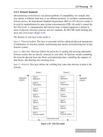
The Redundant Q4AR System Description
The Q4AR CPU gives you redundant system architecture with outstanding
availability for critical processes requiring maximum protection against fail-
ures. In normal operation the control program is executed by the active
CPU; the standby CPU remains essentially idle, just copying the process
data. In the event of an abnormal operating status or failure of the active
VCPU the standby CPU cuts in immediately and takes over control, starting
with the status of the last set of process data copied. To ensure maximum
availability the redundant Q4AR system is installed on an A32RB/A33RB
base unit with the following components:
2 power supply units
2 Q4AR CPUs
2 system control modules
1 bus switching module for connection of the extension base unit
It is also possible to install communications modules for connection to the
redundant NET/10 network in one or two slots on the base unit.
The Process Control System
The AS92R system control modules handle the automatic activation of the
standby CPU, monitoring all the following system functions:
Self-diagnostics of the Q4AR CPU
Q4AR CPU watchdog
AS92R watchdog
5 VDC power supply
24 VDC power supply
Power supply unit errors
When the control is passed to the standby CPU the AS92R system control
module also activates an alarm output. The switchover to the standby CPU
is handled smoothly and under full control, using a process image of the
active CPU (up to 48K words) that is continuously copied by the standby
CPU during normal operation. In the event of a failure the standby CPU cuts
in, using the last process image stored before the error occurred (see dia-
gram at right), guaranteeing smooth continuation of process control.You
can also manually switch the control to either CPU for servicing work with
the key-operated switch on the A6RAF bus switching module. The Q4AR
features an integrated arithmetic coprocessor, which enables it to perform
floating-point math between 10 and 100 times faster than the A3U CPU.
The instruction set of the Q4AR CPU also includes 47 dedicated process
control instructions.
400
Programmable Logic Controllers • A Series Overview
A Series Overview
The CPU and the modules are held in a base unit which has an
internal bus connection for communication between the individual
modules and the CPU. The power supply module which supplies
the voltage for the entire system is also installed on this base unit.
The main base units are available in different versions with a differ-
ent number of module slots. Each base unit can be supplemented
by means of an extension base unit, providing additional slots.
Besides the common base units also redundant systems for
2 CPUs or 2 power supply modules are available. (Q4AR
systems only)
If you wish to keep open the option of subsequent extension of
your PLC or if you have free slots on your main base units, you
can insert dummy modules here. They serve to protect the free
slots from soiling or from mechanical effects but can also be used
for reserving I/O points.
For cabling larger systems and machines—e.g. in a modular
design—the use of remote I/O modules offers additional
communications facilities. These modules are connected by
means of a variety of networking options.
Extension
The main base unit and the extension base units are simply
connected to one another by extension cables. These connecting
cables also supply the extension base units with the operating
voltage of 5 VDC.
Up to seven extension base units can be connected to a main
base unit, over a distance of 6.6m
When choosing the power supply module, the total power
consumption of the I/O modules, of the special function modules,
and of the peripherals must be taken into account. Also the
voltage drop in the connecting cable has to be regarded. If nec-
essary, an extension base with a further power supply module
should be used. (A6xB extension bases)
401
Programmable Logic Controllers • AnN Series CPU Modules
AnN CPU Modules
The AnN CPU line is the basic CPU of the A Series line. The AnN is suitable for a
variety of medium scale control applications.
Special Features:
■ The units can be fitted with non-volatile EPROM and EEPROM memory modules.
■ Integrated programming interface configured as a differential port (RS-422).
■ I/Os processed in direct or refresh I/O operation mode.
■ Support for user password assignment (parameter settings).
■ Wide variety of I/O and special function modules.
■ Network multiple systems using NET/II.
Specifications A2NCPU-UL A2NCPU-S1 A3NCPU-UL
Certification UL• cUL • CE CE UL• cUL • CE
I/O Points 512 1024 2048
Control System Cyclic operation (using stored program)
CPU Self-Diagnostic Functions
Program check, watch dog timer, battery error detection, memory error detection, CPU error detection,
power supply error detection, fuse error detection
Backup Battery All memory cassettes are fitted with a lithium battery with a life expectancy of 5 years
Memory Capacity Up to the capacity of the memory cassette loaded
Memory Type RAM, EPROM RAM, EPROM RAM, EPROM
Memory Cassettes A3NMCA-0 to -56 A3NMCA-0 to -56 A3NMCA-0 to -56
Main Sequence Program Max. 14 k steps Max. 14 k steps Max. 30 k steps
Sub Sequence Program — — Max. 30 k steps
Program
Microcomputer Program Max. 26 kbyte Max. 26 kbyte Max. 58 kbyte
Capacity
File Registers (R) Max. 4096 Max. 4096 Max. 4096
Comments Max. 4032 Max. 4032 Max. 4032
Instruction Execution Time 1 µs/log. instruction 1 µs/log. instruction 1 µs/log. instruction
Timers (T) 256 256 256
Counters (C) 256 256 256
Internal / Special Relays (M) 1000 / 256 1000 / 256 1000 / 256
Data Registers / Special Registers (D) 1024 / 256 1024 / 256 1024 / 256
Interrupt Pointers (I) 32 32 32
Pointers (P) 256 256 256
Annunciators (F) 256 256 256
Accumulators (A) 2 2 2
Index Registers (V, Z) 2 2 2
Link relays (B) / Link Registers (W) 1024 / 1024 1024 / 1024 1024 / 1024
Instructions 259 259 263
Internal Current Consumption (5 VDC) mA
730 730 900
Allowable Instantaneous Power Failure Period
Depends on the power supply used but max. 20 ms
Weight (kg) 0.7 0.7 0.8
Dimensions (W x H x D) mm 79.5 x 250 x 121 79.5 x 250 x 121 79.5 x 250 x 121
MELSEC AnN CPU Modules
Notes:
1. Dependent on one another
2. The number depends on the extended file registers and on the memory configuration used.
402
Programmable Logic Controllers • AnN Series CPU Modules
AnN Data Link CPUs
In addition to the standard AnN CPUs data link versions for coaxial or fiber-optics
connection are also available. The other specifications and the instruction sets are exactly
the same as the standard AnN series CPUs.
Special Features:
■
Can be configured as master or local station in NET/II.
■
No additional slot is necessary for the network interface, as it is built into the CPU.
■
Network status LEDs.
Specifications A2NCPUP21 A2NCPUR21 A3NCPUP21 A3NCPUR21
Certification CE CE CE CE
Communication Method Half duplex, bit serial Half duplex, bit serial Half duplex, bit serial Half duplex, bit serial
Transmission Path Duplex loop Duplex loop Duplex loop Duplex loop
Synchronization Method Frame synchronization Frame synchronization Frame synchronization Frame synchronization
Max. Number of Link
Link Relay (B)
1024 1024 1024 1024
Points in one System
Link Register (W)
1024 1024 1024 1024
Modulation Method CMI CMI CMI CMI
Transmission Format Conforms to HDLC Conforms to HDLC Conforms to HDLC Conforms to HDLC
Stations Per Loop Max. 65 Max. 65 Max. 65 Max. 65
Cable Optical fiber cable Coaxial cable Optical fiber cable Coaxial cable
Communication Rate (Mbit/s) 1.25 1.25 1.25 1.25
Range (m) 1000; overall max. 10000 500; overall max. 10000 1000; overall max. 10000 500; overall max. 10000
Allowable Instantaneous
Power Failure Period
Depends on the power supply used but max. 20 ms
Error Control Method CRC and retry after time-out CRC and retry after time-out CRC and retry after time-out CRC and retry after time-out
RAS Function Loop back function on error detection or cable breakage, diagnostic functions such as link check for all modules
Cables SI-200/250 3C-2V, 5C-2V SI-200/250 3C-2V, 5C-2V
I/O Points 512 512 2048 2048
Internal Current Consumption
(5 VDC) mA
1380 1780 1550 1950
Weight (kg) 0.92 0.92 0.95 0.95
Dimensions (W x H x D) mm 79.5 x 250 x 121 79.5 x 250 x 121 79.5 x 250 x 121 79.5 x 250 x 121
MELSEC AnN Data Link CPU Modules
403
Programmable Logic Controllers • AnA Series CPU Modules
AnA CPU Modules
The AnN CPU offer faster performance and greater internal data storage capabilities
than AnN CPUs for more demanding applications. An extended instruction set also
makes programming complex automation systems an easier task.
Special Features:
■ Can be configured as master or local stations on NET/II.
■ I/Os processed in process and refresh mode.
■ IEEE 754 standard floating point arithmetic.
■ Special instructions for PID control circuits.
■ Mathematical functions, including trigonometric, exponents and logarithms.
■ The AnN series is upwardly compatible to the AnA series.
Specifications A2ACPU A2ACPU-S1 A3ACPU
Certification CE CE CE
I/O Points 512 1024 2048
Control System Cyclic operation (using stored program)
CPU Self-Diagnostic Functions
Program check, watch dog timer, memory error detection, CPU error detection,
power supply error detection, fuse error detection
Backup Battery All memory cassettes are fitted with a lithium battery with a life expectancy of 5 years
Memory Capacity 14k steps 14k steps 30k steps
Memory Type RAM, EPROM RAM, EPROM RAM, EPROM
Memory Cassettes A3NMCA-0 to -56 A3NMCA-0 to -56 A3NMCA-0 to -56
Main Sequence Program 14k steps 14k steps 30k steps
Sub Sequence Program N/A N/A 30k steps
File Registers (R) 8192 8192 8192
Comments 4032 4032 4032
Extended Comments 3968 3968 3968
Instruction Execution Time 200ns 200ns 150ns
Timers (T) 2048 2048 2048
Counters (C) 1024 1024 1024
Internal / Special Relays (M) 8192 / 256 8192 / 256 8192 / 256
Data Registers / Special Registers (D) 6144 / 256 6144 / 256 6144 / 256
Interrupt Pointers (I) 32 32 32
Pointers (P) 256 256 256
Annunciators (F) 2048 2048 2048
Accumulators (A) 222
Index Registers (V, Z) 14 14 14
Link relays (B) / Link Registers (W) 4096 / 4096 4096 / 4096 4096 / 4096
Instructions 461 461 461
Allowable Instantaneous
Power Failure Period
20ms 20ms 20ms
MELSEC AnA CPU Modules
Program
Capacity
404
Programmable Logic Controllers • AnA Series CPU Modules
AnA Data Link CPUs
In addition to the standard AnA CPUs, data link versions for coaxial or fiber optics
connections are also available. The other specifications and the instruction sets are
exactly the same as the standard AnA series CPUs.
Special Features:
■ Can be configured as master or local station on NET/II.
■ No additional slot is necessary for the network interface, as it is built into the CPU.
■ Network status LEDs.
Specifications A2ACPUP21 A2ACPUR21
Certification UL • cUL • CE UL • cUL • CE
I/O Points 1024 1024
Control System Cyclic operation (using stored program)
CPU Self-Diagnostic Functions
Program check, watch dog timer, battery error detection, memory error detection, CPU error detection,
power supply error detection, fuse error detection
Backup Battery All memory cassettes are fitted with a lithium battery with a life expectancy of 5 years
Memory Capacity For all modules up to the capacity of the memory cassette loaded
Memory Type RAM, EPROM RAM, EPROM
Memory Cassettes A3NMCA-0 to -56 A3NMCA-0 to -56
Main Sequence Program Max. 14 kbyte Max. 14 kbyte
Program
Sub Sequence Program — —
Capacity
File Register (R) *2 Max. 8 kbyte b Max. 8 kbyte b
*1
Comments Max. 4032 Max. 4032
Extended Comments Max. 3968 Max. 3968
Instruction Execution Time 0.2 µs/log. instruction 0.2 µs/log. instruction
Timers (T) 2048 (standard: 256) 2048 (standard: 256)
Counters (C) 1024 (standard: 256) 1024 (standard: 256)
Internal / Special Relays (M) 8192 / 256 8192 / 256
Data Registers / Special Registers (D)
6144 / 256 6144 / 256
Interrupt Pointers (I) 32 32
Pointers (P) 256 256
Annunciators (F) 2048 2048
Accumulators ( A) 2 2
Index Registers (V, Z) 14 14
Link Relays (B) / Link Registers (W) 4096 / 4096 4096 / 4096
Instructions 461 461
Allowable Instantaneous
Power Failure Period
Depends on the power supply used but max. 20 ms
MELSEC AnA CPU Data Link CPU Modules
Notes:
1. Dependent on one another (see memory cassettes, page 410).
2. The number of extended file registers available depends on the memory cassettes.
405
Programmable Logic Controllers • AnA Series CPU Modules
AnA Data Link CPUs
In addition to the standard AnA CPUs, data link versions for coaxial or fiber optics
connections are also available. The other specifications and the instruction sets are
exactly the same as the standard AnA series CPUs.
Special Features:
■ Can be configured as master or local station on NET/II.
■ No additional slot is necessary for the network interface, as it is built into the CPU.
■ Network status LEDs.
Specifications A2ACPUP21-S1 A2ACPUR21-S1 A3ACPUP21 A3ACPUR21
Certification UL • cUL • CE UL • cUL • CE UL • cUL • CE UL • cUL • CE
Communication Method Half duplex, bit serial Half duplex, bit serial Half duplex, bit serial Half duplex, bit serial
Transmission Path Duplex loop Duplex loop Duplex loop Duplex loop
Synchronization Method Frame synchronization Frame synchronization Frame synchronization Frame synchronization
Max. No. of Link
Link Relay (B)
1024 1024 1024 1024
Points in One System
,
Link Register (W)
1024 1024 1024 1024
MELSECNET
Max. No. of Link
Link Relay (B)
4096 4096 4096 4096
Points in One System,
Link Register (W)
4096 4096 4096 4096
MELSECNET(II)
Modulation Method CMI CMI CMI CMI
Transmission Format Conforms to HDLC Conforms to HDLC Conforms to HDLC Conforms to HDLC
Stations Per Loop Max. 65 Max. 65 Max. 65 Max. 65
Cable Optical fiber cable Coaxial cable Optical fiber cable Coaxial cable
Communication Speed (Mbit/s) 1.25 1.25 1.25 1.25
Distance (m) 1000; overall max. 10000 500; overall max. 10000 1000; overall max. 10000 500; overall max. 10000
Allowable Instantaneous Depends on the power supply Depends on the power supply Depends on the power supply Depends on the power supply
Power Failure Period used but max. 20 ms used but max. 20 ms used but max. 20 ms used but max. 20 ms
Error Control Method CRC and retry after time-out CRC and retry after time-out CRC and retry after time-out CRC and retry after time-out
RAS Function Loop back function on error detection or cable breakage, diagnostic functions such as link check for all modules
Cable SI-200/250 RG59BU/RG6AU SI-200/250 RG59BU/RG6AU
I/O Points 1024 1024 2048 2048
Internal Current Consumption (DC 5 V) A
1.0 1.4 1.1 1.6
Weight (kg) 0.9 0.9 0.9 1.0
Dimensions (W x H x D) mm 79.5 x 250 x 121 79.5 x 250 x 121 79.5 x 250 x 121 79.5 x 250 x 121
MELSEC AnA Data Link CPU Modules
406
Programmable Logic Controllers • AnU Series CPU Modules
AnU CPU Modules
The AnU CPUs represent the top of the A Series CPU line. They offer the highest
performance combined with the greatest flexibility to tackle the majority of demanding
large scale applications. Additional, the AnU supports NET/10 control level networking
as well as NET/II.
Special Features:
■ I/Os processed in refresh mode.
■ Direct processing and access to PID control circuits.
■ Floating point arithmetic, square root and logarithm functions.
■ Integrated self-diagnostics functions.
■ Controller station for NET/10.
■ Compatible with all MELSEC A series CPU modules.
■ Supports batch processing for data communications.
Specifications A2UCPU A2UCPU-S1 A3UCPU A4UCPU
Certification UL • cUL • CE UL • cUL • CE UL • cUL • CE UL • cUL • CE
I/O Points 512 1024 2048 4096
Control System Cyclic operation (using stored program)
CPU Self-Diagnostics Functions
Program check, watch dog timer, battery error detection, memory error detection, CPU error detection,
power supply error detection, fuse error detection
Backup Battery All memory cassettes are fitted with a lithium battery with a life expectancy of 5 years
Memory Capacity For all modules up to the capacity of the memory cassette loaded
Memory Type RAM, EPROM, EEPROM RAM, EPROM, EEPROM RAM, EPROM, EEPROM RAM, EPROM, EEPROM
Memory Cassettes
A3NMCA-0, 2, 16, 56; A4UMCA-32E, 128E
Main Sequence Program Max. 14 ksteps Max. 14 ksteps Max. 30 ksteps Max. 30 ksteps
Program Sub Sequence Program — — Max. 30 ksteps Max. 30 ksteps x3
Capacity File Register (R) *2 Max. 8192 Max. 8192 Max. 8192 Max. 8192
*1 Comments Max. 4032 Max. 4032 Max. 4032 Max. 4032
Extended Comments Max. 3968 Max. 3968 Max. 3968 Max. 3968
Instruction Execution Time 200ns 200ns 200ns 200ns
Timers (T) 2048 2048 2048 2048
Counters (C) 1024 1024 1024 1024
Internal / Special Relays (M) 8192 / 256 8192 / 256 8192 / 256 8192 / 256
Data registers / Special Registers (D) 8192 / 256 8192 / 256 8192 / 256 8192 / 256
Interrupt Pointers (I) 32 32 32 3
Pointers (P) 256 256 256 256
Annunciators (F) 2048 2048 2048 2048
Accumulators (A) 2 2 2 2
Index Registers (V, Z) 14 14 14 14
Link Relays (B) / Link Registers (W) 8192 / 8192 8192 / 8192 8192 / 8192 8192 / 8192
Instructions 475 475 475 475
Internal Current Consumption (DC 5 V) mA
400 400 500 500
Allowable Instantaneous
Power Failure Period
Depends on the power supply used Depends on the power supply used Depends on the power supply used Depends on the power supply used
Weight (kg) 0.5 0.5 0.6 0.6
Dimensions (W x H x D) mm 79.5 x 250 x 121 79.5 x 250 x 121 79.5 x 250 x 121 79.5 x 250 x 121
MELSEC AnU CPU Modules
Notes:
1. Dependent on one another.
2. The number of extended file registers available depends on the memory configuration.
407
Programmable Logic Controllers • QnA Series CPU Modules
QnA CPU Modules
QnA CPUs offer an advanced multi-program/multi-uses environment that offers
enhanced development productivity and reduced downtime.
Special Features:
■
Up to 124 separate programs to allow even the largest systems to be modularized
and developed concurrently by multiple programmers.
■
NET/10 compatible.
■
Advanced graphical network configuration tools in GX Developer.
■
Very large data capacity (up to 1 MB).
■
Very high performance with optimized CPU throughout.
Specifications Q2ACPU Q2ACPU-S1 Q3ACPU
Certification CE CE CE
Max. I/O (Overall) Device Point 8192 8192 8192
Max. I/O Points on Base Unit 512 1024 2048
CPU Self-Diagnostics Functions Program structure, watch dog timer, battery check, memory test, CPU test, line voltage monitor, fuse test
Backup Battery All modules are fitted with a lithium battery with a durability of 5 years
Memory Type RAM, EEPROM RAM, EEPROM RAM, EEPROM
Program Max. for
Capacity PLC Program
28 k steps 60 k steps 92 k steps
Instruction Execution Time 200ns 200ns 150ns
Timers (T) 2048 2048 2048
Counters (C) 1024 1024 1024
Internal / Special Relays (SM) 8192 / 2048 8192 / 2048 8192 / 2048
Data Registers (D) / Special Registers (SD)
12288 / 2048 12288 / 2048 12288 / 2048
File Registers (R/ZR)* 32768 / 1042432 32768 / 1042432 32768 / 1042432
Interrupt Pointers (I) 48 48 48
Pointers (P) 4096 4096 4096
Annunciators (F) 2048 2048 2048
Index Registers (Z) 16 16 16
Link Relays (B) / Link Registers (W) 8192 / 8192 8192 / 8192 8192 / 8192
Comments Approx. 64k, depending on size of memory card and parameter configuration
Instructions Sequential: 39, others: 722 Sequential: 39, others: 722 Sequential: 39, others: 722
Internal Current Consumption (5 VDC) mA
0.3 0.3 0.3
Max. Compensation Time
at Power Failure (ms)
Depending on power supply unit used, see power supply section
Weight (kg) 0.8 0.8 0.8
Dimensions (W x H x D) mm 79.5 x 250 x 121 79.5 x 250 x 121 79.5 x 250 x 121
MELSEC QnA CPU Modules
*ZR file registers require the use of a memory card.
408
Programmable Logic Controllers • QnA Series CPU Modules
QnA CPU Modules
The Q4A CPU is the most sophisticated, flexible, high performance controller
Mitsubishi offers. It is equal to the most complex, demanding automation tasks.
The Q4ARCPU provides the added security of a redundant system architecture
for critical processes requiring maximum protection against failures.
Special Features:
■
Up to 124 separate programs to allow even the largest systems to be modularized
and developed concurrently by multiple programmers.
■
NET/10 compatible.
■
Advanced graphical network configuration tools in GX Developer.
■
Very large data capacity (up to 1 MB).
■
Very high performance with optimized CPU throughout.
■
The Q4AR CPU has an integrated math coprocessor for extremely fast execution
of floating-point math and high-precision control algorithms.
Specifications Q4ACPU Q4ARCPU
Certification CE CE
Max. I/O Points Overall 8192 8192
Max. I/O Points on Base Unit 4096 4096
CPU Self-Diagnostics Functions Program structure, watch dog timer, battery check, memory test, CPU test, line voltage monitor, fuse test
Backup Battery All modules are fitted with a lithium-battery with a durability of 5 years
Memory Type RAM, EEPROM RAM, EEPROM
Program Max. for
Capacity PLC Program
124 k steps 124 k steps
Instruction Execution Time 75ns 75ns
Timers (T) 2048 2048
Counters (C) 1024 1024
Relays (M) / Special Relays (SM) 8192 / 2048 8192 / 2048
Data Registers (D) / Special Registers (SD)
12288 / 2048 12288 / 2048
File Registers (R/ ZR)* 32768 / 1042432
Interrupt Pointers (I) 48 48
Pointers (P) 4096 4096
Annunciators (F) 2048 2048
Index Registers (Z) 16 16
Link Relays (B) / Link Registers (W) 8192 / 8192 8192 / 8192
Comments Approx. 64k depending on size of memory card and parameter configuration
Instructions Sequential: 39, others: 722 Sequential: 39, others: 769
Internal Current Consumption (5 VDC) mA
0.6 1.4
Max. Compensation Time
at Power Failure ms
Depending on power supply unit used, see power supply section
Weight (kg) 0.8 0.9
Dimensions (W x H x D) mm 79.5 x 250 x 121 79.5 x 250 x 121
QnA CPU Modules
*ZR file registers require the use of a memory card.
409
Programmable Logic Controllers • A/QnA Series Power Supply Units
Specifications A61PEU A61P-UL A62P A63P A65P A68P A61RP A67RP
Certification UL • cUL • CE UL • cUL CE CE — — — UL • cUL • CE
Input
(+10%, -15%) VAC 100–120/200–240 100–120/200–240 100–120/200–240 — 100–120/200–240 100–120/200–240 100–120/200–240 110/125VDC
Voltage
(+30%, -35%) VDC —— — 24 — — — —
Input Frequency (Hz) 50 / 60 (±5%) 50 / 60(±5%) 50 / 60(±5%) — 50 / 60 (±5%) 50 / 60(±5%) 50 / 60(±5%) —
Max. Inrush Current 20 A within 8 ms 20 A within 8ms 20 A within8 ms 100 A within1 ms 20 A within8 ms 20 A within 8ms 20 A within 8ms 20 A within 8ms
Power Consumption 110 VA 110 VA 110 VA 65 W 110 VA 95 VA 110 VA 65W
5 VDC (A) 8 8 5 8 2 — 8 8
Rated Output
24 VDC (A) — — 0.8 — 1.5 — — —
Current +15 VDC (A) —— ———1.2— —
-15 VDC (A) —— ———0.7— —
5 VDC (A) ≥8.8 ≥8.8 ≥5.5 ≥8.5 ≥2.2 — — —
Overcurrent
24 VDC (A) —— ≥1.2 — ≥2.3 — — —
Protection
+15 VDC (A) — — — — — 1.64 — —
-15 VDC (A) — — — — — 0.94 — —
5VDC(A) — — — — — — — >8.8
Overvoltage 5 VDC (V) 5.5 – 6.5 5.5 – 6.5 5.5 – 6.5 5.5 – 6.5 5.5 – 6.5 — — 6.5
Protection
24 VDC (V) —— ————— —
Efficiency ≥65% ≥65% ≥65% ≥65% ≥65% ≥65% ≥65% >65%
Dielectric
Between Primary
Withstand
and 5 VDC / VAC
2830 1500 2830 — 1500 1500 1500
Voltage
Between Primary
and 24 VDC / VAC
— — 2830 — 1500 1500 —
Maximum Power
Interruption Time (ms)
20 20 20 1 20 20 20 <20
Power Indicator All modules provide a power LED
Signal Output for Failure Indication
— Relay — — — — Relay Relay
Terminal Screws M4 x 6 M4 x 6 M4 x 6 M4 x 6 M4 x 6 M3 x 6 M4 x 6 M4 x 6
Connecting Cable AWG 14 – 18 AWG 14 – 18 AWG 14 – 18 AWG 14 – 18 AWG 14 – 18 AWG 14– 18 AWG 14– 18 AWG 14– 18
Weight (kg) 0.8 0.8 0.9 0.8 0.94 0.9 — 0.7
Dimensions (Wx H x D) mm 55 x 250 x 121 55 x 250 x 121 55 x 250 x 121 55 x 250 x 121 55 x 250 x 121 75.5 x 250 x 121 — 55 x 250 x 121
Accessories — — — Replacement fuses
Power Supply Units
Supplies power to the control system, I/O and special function modules.
Select a PSU with sufficient capacity for your system configuration.
Special Features:
■
The operation state is indicated by a red LED.
■
An additional 24 VDC output (A62PEU) supplies special function
modules and external peripherals (e.g. HMI).
■
The A68P is used for the analog output module A616DAV and
A616DAI and occupies 2 slots and 32 I/O points on the base unit.
■
Additional relay output (240 VAC / 24 VDC; 2A) for failure indication
on A61RP & A67RP.
■
Note the A61RP and A67RP are for use with the Q4AR only.
Use two on each base and extension rack.
Power Supply Units
2830VAC,
between FG,
input,
output & LG
410
Programmable Logic Controllers • A/QnA Series Memory Cassettes
Specifications
RAM Memory Capacity 128 448 256 1024
(for Parameter Setting) kbyte
— 16
(96) (144) (144) (144)
ROM Sockets Two 28-pin sockets (in all memory cassettes)
Loadable ROM Type Usable for all memory cassettes: 4KROM, 8KROM, 16KROM
Loadable RAM Type 4K-RAM These cassette have RAM memory already installed
Weight (kg) 0.13 0.13 0.13 0.15 0.15 0.15
Dimensions (W x H x D) mm 79.5 x 33 x 110
MELSEC A Memory Cassettes
Memory cassettes are available for permanent program storage. The cassettes contain CMOS RAM
memory chips with a variety of capacities. The memory can be used for storing PLC programs, parame-
ter data, comments and operands. The contents of the cassettes’ memory is protected by an integrated
lithium battery. Two sockets are provided for the installation of EPROM memory chips. Unused memory
in the cassettes can be used as an additional data area (the SWO-FN1 software is necessary for doing
this with the AnN CPUs).
Specifications 4KEROM 4KRAM 4KROM 4KEROM 8KROM 16KROM
Chip Type EEPROM RAM EPROM EPROM EPROM EPROM
Number of Pins 28-PIN IC 28-PIN IC 28-PIN IC 28-PIN IC 28-PIN IC 28-PIN IC
Numbers Included 2 2 2 (SET) 2 (SET) 2 (SET) 2 (SET)
Amount of Statements 6k 6k 6k (SET) 14k (SET) 30k (SET) 30k (SET)
Programming Voltage (V) — — 21 12.5 12.5 12.5
Memory Capacity (kbyte) 8 8 8 16 16 32
Supported CPUs A1NCPU All MELSEC A-CPUs
Memory Chips
Memory Chips for A Series Memory Cassettes
A selection of different memory chips are available for the MELSEC A series memory cassettes.
You must always use two chips of the same type in each cassette, which is equal to a set.
MELSEC QnA Memory Cards
The QnA CPUs all have a permanently installed RAM. This memory can be extended with a variety of memory cards. The combination cards
(with two memory types) have a non-volatile EEPROM or flash memory which is programmable by GX Developer.
Specifications Q1MEM-64S Q1MEM-128S Q1MEM-256S Q1MEM-512S Q1MEM-1MS Q1MEM-2MS
Certification ————— —
Memory Type Card Card Card Card Card Card
Memory Capacity 64 kB SRAM 128 kB SRAM 256 kB SRAM 512 kB SRAM 1 Mb SRAM 2 Mb SRAM
Specifications Q1MEM-256SF Q1MEM-512SF Q1MEM-1MSF Q1MEM-2MSF
Certification ————
Memory Type Card Card Card Card
Memory Capacity
128 kB SRAM 256 kB SRAM 512 kB SRAM 1 M SRAM
128 kB Flash 256 kB Flash 512 kB Flash 1 M Flash
Specifications Q1MEM-64SE Q1MEM-128SE Q1MEM-256SE Q1MEM-512SE Q1MEM-1MSE
Certification —————
Memory Type Card Card Card Card Card
Memory Capacity
32 kb SRAM 64 kb SRAM 128 kb SRAM 256 kb SRAM 512 kb SRAM
32 kb EEPROM 64 kb EEPROM 128 kb EEPROM 256 kb EEPROM 512 kb EEPROM
A3N
MCA-0
A3N
MCA-2
A3N
MCA-16
A3N
MCA-56
A4U
MCA-32E
A4U
MCA-128E
411
Programmable Logic Controllers • QnA Series Memory Cards
Specifications A32B-E-UL A35B-E-UL A38B-E-UL A38HB*
Certification UL • cUL UL • cUL • CE UL • cUL CE
I/O Slots 258 8
Installation All base units are provided with 6 mm Ø mounting holes and M5 screws
Weight (kg) .96 1.5 1.9 1.9
Dimensions (W x H x D) mm 247 x 250 x 29 382 x 250 x 29 480 x 250 x 29 480 x 250 x 29
The main base unit accommodates and connects the CPU and the power
supply, input, output and special function modules.
Special Features:
■ Module addressing is automatic, with an eight-slot base unit assumed
as the default. Empty or nonexistent slots (i.e. in units with fewer than 8
slots) are automatically assigned 16 addresses. You can change the
automatic address allocation with GX Developer.
■ DIN rail or bolt mounting.
■ Modules slot into place and are held with a retaining screw.
■ Use with A and QnA CPUs.
The extension base units are connected to the main base unit with extension
cables, enabling configuration of an A series system with up to 64 I/O
modules. You can choose from extension base units with or without a slot
for power supply modules.
Special Features:
■ You can connect a maximum of seven extension base units to each main
base unit.
■ The maximum distance between the first and the last base unit is 6.6 m.
■ Use with A and QnA CPUs.
Extension base units with a power supply module are required in the
following circumstances:
■ When the total power consumption of the installed modules exceeds the
capacity of the power supply module on the main base unit.
■ When the supply voltage falls to below 4.75 V as a result of the voltage
drop along the main to the extension base unit path.
Specifications A52B-UL A55B-UL A58B-UL A62B-UL A65B-UL A68B
Power Supply Slots —— — 1 11
I/O Slots 25 8 258
Installation All base units are provided with 6 mm Ø mounting holes and M5 screws
Weight (kg) 0.96 1.2 1.7 1.1 1.4 1.9
Dimensions (W x H x D) mm 247 x 250 x 29 297 x 250 x 29 411 x 250 x 29 238 x 250 x 29 252 x 250 x 29 466 x 250 x 29
MELSEC A/QnA Extension Base Units
MELSEC A/QnA Main Base Units
*For QnA CPUs only; optional high speed back plane.
412
Programmable Logic Controllers • A/QnA Series Base Units
The redundant main base units are used to install and connect the
system CPUs, power supply units and other modules. They feature
twin CPU / power supply unit slots for the configuration of redundant
systems.
Special Features:
■ Redundant systems (A32RB and A33RB) configurable with
an AS92R system control module on each side of the rack
and an A6RAF bus switching module.
■ The base units themselves are mounted with screws. The
modules have a snap-in mechanism and are additionally
secured with screws.
Specifications A32RB A33RB A37RHB
Certification ———
Application Redundant Q4AR system Redundant Q4AR system Stand-alone Q4AR system
I/O Slots 2 3 7
Other Slots 1 power supply unit and 1 CPU on either side 1 power supply unit and 1 CPU on either side 2 power supply units and 1 CPU module
Fastening All base units are provided with Ø6 mm mounting holes and M5 screws
Weight (kg) 2.2 2.6 2.2
Dimensions (W x H x D) mm 494 x 250 x 29 570 x 250 x 29 497 x 250 x 29
The extension base unit is connected to
the main base unit with a special bus
cable. This extension base unit can be
connected to both conventional and redun-
dant main base units, enabling expansion
of your QnA system with up to a maximum
of 64 I/O modules. The extension base unit
has two slots for power supply units.
Special Features:
■ Redundant power supply unit slot.
■ The base units themselves are mount
with screws. The modules have a snap-in
mechanism and are additionally secured
with screws.
Specifications A68RB
Certification —
Application Q4AR and other QnA systems
I/O Slots 8
Other Slots 2 power supply units
Fastening All base units are provided with Ø6 mm mounting holes and M5 screws
Weight (kg) 2.4
Dimensions (W x H x D) mm 522 x 250 x 29
MELSEC QnA Redundant Main Base Unit
MELSEC QnA Redundant Extension Base Unit
Connection Cable for Base Units
The connection cables AC06B, AC12B and AC30B are used for connecting main base units to the extension base
units. The A1SC05NB cable is used for connecting MELSEC A/QnA series base units to AnS/QnAS series base units.
Connection of a base unit of the A/Q series to an A800GOT/A900GOT operator panel is also possible. The
A1SC07NB-S1 cable is used for connecting a AnS extension base unit to a MELSEC A/QnA series main base unit.
Specifications AC06B AC12B AC30B A1SC05NB A1SC07NB-S1
For Extension Base Units Type
MELSEC A/QnA, MELSEC A/QnA, MELSEC A/QnA, MELSEC A/QnA, MELSEC AnS/QnAS
MELSEC A/QnA to A870GOT MELSEC A/QnA to A870GOT MELSEC A/QnA to A870GOT to AnS/QnAS to MELSEC A/QnA
Length (m) 0.6 1.2 3.0 0.45 0.7
Ohmic Resistance R of the Cable (Ω) 0.019 0.028 0.052 0.037 0.045
MELSEC A/QnA
Connection Cables
413
Programmable Logic Controllers • A/QnA Series Input Modules
MELSEC A/QnA Input Modules
Specifications AX11 AX20-UL
Certification UL • cUL UL • cUL
Number of Input Points 32 points 16 points
Insulation System Photocoupler Photocoupler
Rated Input Voltage 100-120 AC 50/60Hz 200-240 AC 50/60Hz
Rated Input Current 10mA (100 VAC 60Hz) 10mA (200 VAC 60Hz)
Operating Voltage Range 85 to 132V AC (50/60HZ ±5%) 170 to 264 VAC (50/60HZ ±5%)
Max. Simultaneous ON 60% (20 points) 100% (16 points)
Inrush Current Max. 300mA, within 0.3ms (132 VAC) Max. 600mA, within 0.12ms (264V AC)
ON Voltage / ON Current 80 VAC or higher / 6mA or higher 160 VAC or higher / 5.5mA or higher
OFF Voltage / OFF Current 40 VAC or lower / 4mA or lower 70 VAC or lower / 3.5mA or lower
Input Impedance
Approx. 10kΩ (60Hz), approx. 12kΩ (50Hz) Approx. 22kΩ (60Hz), approx. 24kΩ (50Hz)
Response
OFFON 15ms or less 15ms or less
Time
ONOFF 25ms or less 25ms or less
Internal Current Consumption (5 VDC) 110mA (TYP. all points ON) 55mA (TYP. all points ON)
Common Terminal Arrangement
32 points/common (common 16 points/common (common
terminal: TB9, TB18, TB27, TB36) terminal: TB9, TB18)
Indication 1 LED per points 1 LED per points
Connection Method
38-point removable terminal block 20-point removable terminal block
(M3 x 6mm metric screw) (M3 x 6mm metric screw)
Applicable Wire Size 0.75 to 2 mm
2
(18 to 14 AWG) (tightening torque: 7kg•cm (0.505lbs•ft))
Applicable Solderless Terminal 1.25-3, 1.25-YS3A, 2-S3, 2-YS3A, V1.25-3, V1.25-YS3A, V2-S3, V2-YS3A
MELSEC A/QnA Input Modules
Specifications AX21 AX31
Certification ——
Number of Input Points 32 points 16 points
Insulation System Photocoupler Photocoupler
Rated Input Voltage 200-240 AC 50/60Hz 12/24VDC, 12/14 VAC 50/60Hz
Rated Input Current 10mA (220 VAC 60Hz) 4mA (12 VAC/’DC), 8.5mA (24 VAC/DC)
Operating Voltage Range 170 to 264 VAC (50/60HZ ±5%)
10.2 to 26.4 VDC, 10.2 to 26.4 VDC
ripple ratio: within 5% (50/60Hz ±5%)
Max. Simultaneous ON 60% (20 points) 100% simultaneously ON (26.4 VAC)
Inrush Current Max. 600mA, within 0.12ms (264 VAC) —
ON Voltage / ON Current 160 VAC or higher / 5.5mA or higher 7 VDC/AC or higher /2mA or higher
OFF Voltage / OFF Current 70 VAC or lower / 3.5mA or lower 2.5 VDC/AC or lower /0.7mA or lower
Input Impedance Approx. 22kΩ (60Hz), approx. 24kΩ (50Hz) Approx. 2.7kΩ
OFFON 15ms or less
30ms or less, 35ms or less
Response (12/24 VDC), (12/24 VAC, 60Hz)
Time
ONOFF 25ms or less
30ms or less, 30ms or less
(12/24 VDC), (12/24 VAC, 60Hz)
Internal Current Consumption (5 VDC) 110mA (TYP. all points ON) 110mA (TYP. all points ON)
Common Terminal Arrangement
32 points/common (common 32 points/common (common
terminal: TB9, TB18, TB27, TB36) terminal: TB9, TB18)
Indication 1 LED per points 1 LED per points
Connection Method
38-point removable terminal block 38-point removable terminal block
(M3 x 6mm metric screw) (M3 x 6mm metric screw)
Applicable Wire Size 0.75 to 2 mm
2
(18 to 14 AWG) (tightening torque: 7kg•cm (0.505lbs•ft))
Applicable Solderless Terminal 1.25-3, 1.25-YS3A, 2-S3, 2-YS3A, V1.25-3, V1.25-YS3A, V2-S3, V2-YS3A
414
Programmable Logic Controllers • A/QnA Input Modules
MELSEC A/QnA Input Modules
Specifications AX40-UL AX41-UL AX41-S1
Certification UL • cUL • CE UL • cUL • CE CE
Number of Input Points 16 points 32 points 32 points
Insulation System Photocoupler Photocoupler Photocoupler
Rated Input Voltage 12 VDC 24 VDC 12 VDC 24 VDC 12 VDC 24 VDC
Rated Input Current 4mA 10mA 4mA 10mA 4mA 10mA
Operating Voltage Range 10.2 to 26.4 VDC ripple ratio: within 5% 10.2 to 26.4 VDC ripple ratio: within 5% 10.2 to 26.4 VDC ripple ratio: within 5%
Max. Simultaneous ON 100% (8 points/common) 60% (5 points/common) 60% (5 points/common)
ON Voltage/ON Current 9.5 VDC or higher / 3mA or higher 9.5 VDC or higher / 3mA or higher 9.5 VDC or higher / 3mA or higher
OFF Voltage/OFF Current 6 VDC or lower / 1.5mA or lower 6 VDC or lower / 1.5mA or lower 6 VDC or lower / 1.5mA or lower
Input Impedance Approx. 2.4kΩ Approx. 2.4kΩ Approx. 2.4kΩ
Response
OFFON 10ms or less 10ms or less 0.1ms or less
Time
ONOFF 10ms or less 10ms or less 0.2ms or less
Internal Current Consumption (5 VDC) 55mA (TYP. all points ON) 110mA (TYP. all points ON) 110mA (TYP. all points ON)
Common Terminal Arrangement
8 points/common (common 8 points/common (common 8 points/common (common
terminal: TB9, TB18) terminal: TB9, TB18, TB27, TB36) terminal: TB9, TB18, TB27, TB36)
Indication 1 LED per point 1 LED per point 1 LED per point
Connection Method
20-point removable terminal block 38-point removable terminal block 38-point removable terminal block
(M3 x 6mm metric screw) (M3 x 6mm metric screw) (M3 x 6mm metric screw)
Applicable Wire Size 0.75 to 2 mm
2
(18 to 14 AWG) (tightening torque: 7kg•cm (0.505lbs•ft))
Applicable Solderless Terminal 1.25-3, 1.25-YS3A, 2-S3, 2-YS3A, V1.25-3, V1.25-YS3A, V2-S3, V2-YS3A
MELSEC A/QnA Input Modules
Specifications AX42 AX42-S1 AX50-S1
Certification CE — CE
Number of Input Points 64 points 64 points 16 points
Insulation System Photocoupler Photocoupler Photocoupler
Rated Input Voltage 12 VDC 24 VDC 12 VDC 24 VDC 48 VDC
Rated Input Current 3mA 7mA 3mA 7mA 4mA
Operating Voltage Range 10.2 to 26.4 VDC ripple ratio: within 5% 10.2 to 26.4 VDC ripple ratio: within 5% 38.4 to 57.6 VDC ripple ratio: within 5%
Max. Simultaneous ON 60% (20 points/common) 60% (20 points/common) 100% (8 points/common)
ON Voltage / ON Current 9.5 VDC or higher /3mA or higher 9.5 VDC or higher /3mA or higher 34 VDC or higher /3mA or higher
OFF Voltage / OFF Current 6 VDC or lower /1.5mA or lower 6 VDC or lower /1.5mA or lower 10 VDC or lower /1mA or lower
Input Impedance Approx. 3.4kΩ Approx. 3.4kΩ Approx. 11kΩ
Response
OFFON 10ms or less 0.5ms or less 10ms or less
Time
ONOFF 10ms or less 0.5ms or less 10ms or less
Internal Current Consumption (5 VDC) 120mA (TYP. all points ON) 120mA (TYP. all points ON) 55mA (TYP. all points ON)
Common Terminal Arrangement
32 points/common (common 32 points/common (common 8 points/common (common
terminal: 1B1, 1B2, 2B1, 2B2) terminal: 1B1, 1B2, 2B1, 2B2) terminal: TB9, TB18)
Indication
1 LED per two points 1 LED per two points
1 LED per point
(switch selection of block of 32 points) (switch selection of block of 32 points)
Connection Method 2 40-pin connectors (with solder) 2 external wiring connectors
20-point removable terminal block
(M3 x 6mm metric screw)
Applicable Wire Size 0.3mm
2
(23 AWG) 0.3mm
2
(23 AWG)
0.75 to 2mm
2
(18 to 14 AWG)
(tightening torque: 7kg•cm (0.505lbs•ft))
Applicable Solderless Terminal ——
1.25-3, 1.25-YS3A, 2-S3, 2-YS3A,
V1.25-3, V1.25-YS3A, V2-S3, V2-YS3A
Accessory Two external wiring connectors Two external wiring connectors —
415
Programmable Logic Controllers • A/QnA Series Input Modules
MELSEC A/QnA Input Modules
Specifications AX21EU AX70 AX70-UL AX71
Certification UL • cUL • CE CE UL • cUL CE
Input Points 16 points 16 points 32 points 32 points
Isolation Method All modules fitted with photocoupler isolation between input terminals and PLC power
Rated Input Voltage 200 – 240 VAC (50 / 60 HZ) 5 / 12 / 24 VDC 5 / 12 / 24 VDC 5 / 12 / 24 VDC
Operating Voltage Range
170 – 264 VAC (50 / 60 HZ, ±5%) 4.5 – 5.5 VDC, 10.2 – 26.4 VDC 4.5 – 5.5 VDC, 10.2 – 26.4 VDC 4.5 – 5.5 VDC, 10.2 – 26.4 VDC
Max. Input Points Simultaneously ON 60% 100% 100% 100%
Max. Inrush Current 600 mA for 0.5 ms (at 264 VAC) — — —
Rated Input Current 12 mA (220 VAC, 60 Hz) Max. 5.5 / 3 / 6 mA Max. 5.5 / 3 / 6 mA Max. 5.5 / 3 / 6 mA
OFFON
Voltage (V) ≥ AC 160 ≥ DC 3.5 or DC 5 ≥ DC 3.5 or DC 5 ≥ DC 3.5 or DC 5
Current (mA) ≥ AC 5.5 ≥ DC 1.0 ≥ DC 1.0 ≥ DC 1.0
ONOFF
Voltage (V) ≥ AC 70 ≥ DC 1.1 or DC 2 ≥ DC 1.1 or DC 2 ≥ DC 1.1 or DC 2
Current (mA) ≥ AC 3.5 ≥ DC 0.2 ≥ DC 0.2 ≥ DC 0.2
Load Resistance (kΩ)
Approx. 24 (50 Hz) Approx. 1.4 switch → ON Approx. 1.4 switch → ON Approx. 1.4 switch → ON
Approx. 22 (60 Hz) Approx. 5.5 switch → OFF Approx. 5.5 switch → OFF Approx. 5.5 switch → OFF
Response Time
OFFON (ms) ≤15 ≤1.5 ≤1.5 ≤1.5
ONOFF (ms) ≤ 25 ≤ 3 ≤ 3 ≤ 3
Common Terminal Arrangement Points 32 8 8 8
Input Indicator All modules provide a red power LED for each input
No. of Occupied I/O Points 32 16 16 32
Applicable Wire Size (mm
2
) 0.75 – 2 0.75 – 2 0.75 – 2 0.75 – 2
Internal Current Consumption (5 VDC) mA 150 (all input points ON) 55 (all input points ON) 55 (all input points ON) 110 (all input points ON)
Weight (kg) 0.5 0.36 0.36 0.45
Dimensions (W x H x D) mm 37.5 x 250 x 121 37.5 x 250 x 121 37.5 x 250 x 121 37.5 x 250 x 121
MELSEC A/QnA Input Modules
Specifications AX80E AX80-UL AX81
Certification CE UL • cUL CE
Input Points 16 16 32
Isolation Method All modules fitted with photocoupler isolation between input terminals and PLC power
Rated Input Voltage 12 / 24 VDC 12 / 24 VDC 12 / 24 VDC
Operating Voltage Range 10.2 – 26.4 VDC 10.2 – 26.4 VDC 10.2 – 26.4 VDC
Max. Input Points Simultaneously ON 100% 100% 60%
Max. Inrush Current —— —
Rated Input Current (mA) 4 / 10 4 / 10 4 / 10
OFFON
Voltage (V) ≥ DC 9.5 ≥ DC 9.5 ≥ DC 9.5
Current (mA) ≥ DC 2.6 ≥ DC 2.6 ≥ DC 3
ONOFF
Voltage (V) ≤ DC 6 ≤ DC 6 ≤ DC 6
Current (mA) ≤ DC 1 ≤ DC 1 ≤ DC 1.5
Load Resistance (kΩ) Approx. 2.4 Approx. 2.4 Approx. 2.4
Response Time
OFFON (ms) ≤ 5.5 (0.5 in high-speed mode) ≤ 5.5 (0.5 in high-speed mode) ≤ 10
ONOFF (ms) ≤ 6.0 (1.0 in high-speed mode) ≤ 6.0 (1.0 in high-speed mode) ≤ 10
Common Terminal Arrangement Points 88 8
Input Indicator All modules provide a red power LED for each point
No. of Occupied I/O Points 16 16 32
Applicable Wire Size (mm
2
) 0.75 – 2 0.75 – 2 0.75 – 2
Internal Current Consumption (5 VDC) mA 55 55 110
Weight (kg) 0.36 0.36 0.45
Dimensions (W x H x D) mm 37.5 x 250 x 121 37.5 x 250 x 121 37.5 x 250 x 121
416
Programmable Logic Controllers • A/QnA Series Input Modules
MELSEC A/QnA Input Modules
Specifications AX81-S1 AX81-S2 AX82
Certification CE — CE
Input Points 32 32 64
Isolation Method All modules fitted with photocoupler isolation between input terminals and PLC power
Rated Input Voltage 48 / 60 VDC 48 / 60 VDC 12 / 24 VDC
Operating Voltage Range 41 – 66 VDC 41 – 66 VDC 10.2 – 26.4 VDC
Max. Input Points Simultaneously ON 60% 60% 60%
Max. Inrush Current ———
Rated Input Current (mA) 3 / 4 3 / 4 3 / 7
OFF
ON
Voltage (V) ≥ DC 31 ≥ DC 31 ≥ DC 9.5
Current (mA) ≥ DC 1.7 ≥ DC 1.7 ≥ DC 2.6
ON
OFF
Voltage (V) ≤ DC 10 ≤ DC 10 ≤ DC 6
Current (mA) ≤ DC 0.5 ≤ DC 0.5 ≤ DC 1.0
Load Resistance (kΩ) Approx. 18 Approx. 18 Approx. 3.4
Response Time
OFF
ON (ms) ≤ 20 ≤ 20 ≤ 10
ONOFF (ms) ≤ 20 ≤ 20 ≤ 10
Common Terminal Arrangement Points 888
Input Indicator All modules provide a red power LED for each point
No. of Occupied I/O Points 32 32 64
Applicable Wire Size (mm
2
) 0.75 – 2 0.75 – 2 0.75 – 2
Internal Current Consumption (5 VDC) mA 125 125 120
Weight (kg) 0.45 0.45 0.45
Dimensions (W x H x D) mm 37.5 x 250 x 121 37.5 x 250 x 121 37.5 x 250 x 121
MELSEC A/QnA Input Module
Specifications AX60-S1
Certification —
Number of Input Points 16 points
Insulation System Photocoupler
Rated Input Voltage 100/110/125 VDC
Rated Input Current 2mA
Max. Inrush Current 65mA (121 VDC), 75mA (140 VDC)
Operating Voltage Range 85 to 140 VDC ripple ratio: within 5%
Max. Simultaneous ON 100% (8 points/common)
ON Voltage/ON Current 80 VDC or higher / 1.4mA or higher
OFF Voltage/OFF Current 20 VDC or lower / 0.5mA or lower
Input Impedance Approx. 50kΩ
Response
OFFON 10ms or less
Time
ONOFF 20ms or less
Internal Current Consumption (5 VDC) 55mA (TYP. all points ON)
Common Terminal Arrangement 8 points/common
Indication 1 LED per point
Connection Method 20-point removable terminal block (M3 x 6mm metric screw)
Applicable Wire Size 0.75 to 2 mm
2
(18 to 14 AWG) (tightening torque: 7kg•cm (0.505lbs•ft))
Applicable Solderless Terminal 1.25-3, 1.25-YS3A, 2-S3, 2-YS3A, V1.25-3, V1.25-YS3A, V2-S3, V2-YS3A
417
Programmable Logic Controllers • A/QnA Series Output Modules
MELSEC A/QnA Output Modules
Specifications AY10 AY10-UL AY11-UL
Certification — UL • cUL UL • cUL
Output Points 16 points
Insulation System Photocoupler
Rated Switching Voltage / Current 24 VDC 2A (resistive load) / point 240 VAC 2A (COS 0=1) / point, (but 8A per common)
Min. Switching Load 5 VDC 1mA
Max. Switching Voltage 264 VAC, 125 VDC
Response Time
OFFON 10 msec or lower
ONOFF 12 msec or lower
Mechanical 20 million times or more
Life
At rated switching voltage / current load; 200 thousand times or more
Electrical
200 VAC 1.5A, 240 VAC 1A (COS 0=0.7); 200 thousand times or more
200 VAC 1A, 240 VAC 0.5A (COS 0=0.35); 200 thousand times or more
24 VDC 1A, 100 VDC 0.1A (L/R=7msec); 200 thousand times or more
Maximum Switching Frequency 3600 times / hour
Surge Suppression Not provided Not provided Varistor (387 to 473V)
Internal Current Consumption (5 VDC) 115 mA (TYP. all points ON)
Relay Socket Not provided Not provided Provided
Common Terminal Arrangement 8 points/common (common terminal: TB9, TB18)
Indication 1 LED per point
External Power
Voltage 24 VDC ±10 (ripple voltage: 4Vp-p or lower)
Supply for Current
Current
150 mA (24 VDC TYP, all points ON)
Connection Method 20-point removable terminal block (M3 x 6mm metric screw)
Applicable Wire Size 0.75 to 2 mm
2
(18 to 14 AWG) (tightening torque: 7kg•cm (0.505 lbs•ft))
Applicable Solderless Terminal 1.25-3, 1.25-YS3A, 2-S3, 2-YS3A, V1.25-3, V1.25-YS3A, V2-S3, V2-YS3A
MELSEC A/QnA Output Modules
Specifications AY11A AY11E AY13 AY13E
Certification CE CE CE CE
Output Points 16 points 16 points 32 points 32 points
Insulation System Photocoupler
24 VDC 2A (resistive load)/point 24 VDC 2A (resistive load)/point 24 VDC 2A (resistive load)/point
24 VDC 2A (resistive load):
Rated Switching Voltage / Current
point, 5A/common
240 VAC 2A(COS 0=1)/point, 240 VAC 2A(COS 0=1)/point, 240 VAC 2A(COS 0=1)/point, 240 VAC 2A(COS 0=1)/point,
(but ≤ 16A per common) (but ≤ 8A per common) (but ≤ 5A per common) (but ≤ 5A per common)
Min. Switching Load 5 VDC 1mA
Max. Switching Voltage 264 VAC, 125 VDC 250 VAC, 125 VDC 264 VAC, 125 VDC 250 VAC, 125 VDC
Response Time
OFFON 10msec or lower
ONOFF 12msec or lower
Mechanical 20 million times or more
Life
At rated switching voltage / current load; 200 thousand times or more
Electrical
200 VAC 1.5A, 240 VAC 1A (COS 0=0.7); 200 thousand times or more
200 VAC 1A, 240 VAC 0.5A (COS 0=0.35); 200 thousand times or more
24 VDC 1A, 100 VDC 0.1A (L/R=7msec);
200 thousand times or more
Maximum Switching Frequency 3600 times/hour
Noise Suppression Varistor (387 to 473V) Varistor (387 to 473V) Not provided Not provided
Fuse — 8A MF51NM8 — 8A MF51NM8
Fuse Blow Indication — Not provided — Not provided
Internal Current Consumption (5 VDC) 115mA (TYP. all points ON) 115mA (TYP. all points ON) 230mA (TYP. all points ON) 230mA (TYP. all points ON)
Relay Socket Not provided Not provided Not provided Not provided
Common Terminal Arrangement
Not provided 8 points/common (common 8 points/common (common 8 points/common (common
(all points independent) terminal: TB9, TB18) terminal: TB9, TB18, TB27, TB36) terminal: TB9, TB18, TB27, TB36)
Indication 1 LED per point
External Power
Voltage 24 VDC ±10 (ripple voltage: 4Vp-p or lower)
Supply for Current Current 1
50 mA (24 VDC TYP, all points ON) 150 mA (24 VDC TYP, all points ON) 290 mA (24 VDC TYP, all points ON) 290 mA (24 VDC TYP, all points ON)
Connection Method
20-point removable terminal 20-point removable terminal 38-point removable terminal 38-point removable terminal
block (M3 x 6mm metric screw) block (M3 x 6mm metric screw) block (M3 x 6mm metric screw) block (M3 x 6mm metric screw)
Applicable Wire Size 0.75 to 2 mm
2
(18 to 14 AWG) (tightening torque: 7kg•cm (0.505lbs•ft))
Applicable Solderless Terminal 1.25-3, 1.25-YS3A, 2-S3, 2-YS3A, V1.25-3, V1.25-YS3A, V2-S3, V2-YS3A
418
Programmable Logic Controllers • A/QnA Series Output Modules
MELSEC A/QnA Output Modules
Specifications AY22 AY40-UL
Certification — UL • cUL
Output Points 16 points 16 points
Insulation System Photocoupler Photocoupler
Rated Load Voltage 100-240 VAC 50 / 60Hz ±5% 12 / 24 VDC
Operating Load Voltage Range — 10.2 to 40 VDC
Max. Load Voltage 264 VAC —
Max. Load Current 2A / point, 3.3A / common 0.1A / point, 0.8A / common
Min. Load Voltage, Current 24 VAC 100mA, 100 VAC 10mA, 240 VAC 20mA —
Max. Inrush Current 40A—10ms or shorter, 15A—100ms or shorter 0.4A
Leakage Current (OFF) 1.5mA (120 VAC 60Hz), 3mA (240 VAC 60Hz) 0.1 mA or lower
Max. Voltage Drop (ON)
1.5V or lower (1 to 2A), 1.8V or lower (0.2 to 1A), 5V or lower (0.2A or lower)
2.5V or lower (0.1A), 1.75V (5mA), 1.7V (1mA)
Response
OFFON 1ms or less 2 ms or less
Time
ONOFF 0.5 cycles + 1ms or less 2 ms or less (resistive load)
Internal Current Consumption (5 VDC) 305mA (TYP. all points ON) 115 mA (TYP. all points ON)
External Power
Voltage — 12 / 24 VDC (10.2 to 40 VDC)
Supply Requirements
Current — 8 mA (24 VDC TYP, per common)
Noise Suppression CR absorber (0.022µ F+47Ω), Varistor (387 to 473) Clamp diode
Fuse Rating 7A fast blow fuse (1 fuse per common) type HP-70K —
Fuse Blow Indicator LED on unit front. Signal to PC CPU —
Common Terminal Arrangement 8 points / common (common terminal: TB9, TB18) 8 points / common (common terminal: TB10, TB20)
Indication 1 LED per point
Connection Method 20-point removable terminal block (M3 x 6mm metric screw)
Applicable Wire Size 0.75 to 2 mm
2
(18 to 14 AWG) (tightening torque: 7kg•cm (0.505l b•ft))
Applicable Solderless Terminal 1.25-3, 1.25-YS3A, 2-S3, 2-YS3A, V1.25-3, V1.25-YS3A, V2-S3, V2-YS3A
MELSEC A/QnA Output Modules
Specifications AY23 AY60EP
Certification CE CE
Output Points 32 points 16 points
Output Type Triac Transistor
Common Terminal Arrangement 88
Isolation Method Photocoupler Photocoupler
Rated Output Voltage 100 / 240 VDC / (40 – 70 Hz) 12 / 24 VDC
Operating Load Voltage Range — 10.2 – 26.4 VDC
24 VAC (100 mA)
Min. Switching Load 100 VAC (10 mA) —
240 VAC (10 mA)
Max. Switching Voltage 264 VAC —
Max. Load
Per Point (A) 0.6 2 / 0.8 (60% ON)
Current Per Common (A) 2.4 —
Max. Inrush Current
20 A for ≤ 10 ms, 8 A for ≤ 100 ms No limit
Leakage Current 1.5 mA 9120 VAC)
with Output OFF
3 MA (240 VAC)
0.1
Response
OFF
ON (ms) ≤ 1 ≤ 0.5
Time
ON
OFF (ms) ≤ 0.5 cycles + 1 ms ≤ 1.5
Lifetime of Contacts ——
Max. Switching Frequency ——
Noise Suppression Filter CR (0.22 µF, 47 Ω) Zener diode
Short Circuit Suppression Fuse 3.2 A, GP-32 Electronic
Output Indicator All modules provide a red power LED for each output
Error Indicator LED —
No. of Occupied Points 32 16
Applicable Wire Size (mm
2
) 0.75 – 2 0.75 – 2
External Power
Current (mA) ——
Supply
Voltage (VDC) ——
Internal Current Consumption (5 VDC) mA
590 115
Weight (kg) 0.55 0.55
Dimensions (W x H x D) mm 37.5 x 250 x 121 37.5 x 250 x 121
419
Programmable Logic Controllers • A/QnA Series Output Modules
MELSEC A/QnA Output Modules
Specifications AY40A AY41-UL AY41-S1
Certification — — UL • cUL • CE
Output Points 16 points 32 points
Insulation System Photocoupler Photocoupler
Rated Load Voltage 12 / 24 VDC 12 / 24 VDC
Operating Load Voltage Range 10.2 to 30 VDC (Max. applied voltage) 10.2 to 40 VDC
Max. Load Current 0.3A / point 0.1A / point, 1.6A / common
Max. Inrush Current 1A, 100ms or lower 0.4A
Leakage Current (OFF) 0.1 mA or lower 0.1mA or lower
Max. Voltage Drop (ON)
1.5V or lower (50 mA to 0.3A), 1.0V (5 mA or lower)
2.5V or lower (0.1A), 1.75V (5mA), 1.7V (1mA)
Response
OFFON 2 msec or less 2 ms or less
Time
ONOFF 2 msec or less (resistive load) 2 ms or less (resistive load)
Internal Current Consumption (5 VDC) 190 mA (TYP. all points ON) 230 mA (TYP. all points ON)
External Power
Voltage — 12 / 24V DC (10.2 to 40 VDC)
Supply Requirements
Current — 20 mA (24 VDC TYP, per common)
Noise Suppression Diode for absorbing noise Clamp diode
Common Terminal Arrangement Not provided (all points independent) 16 points / common (common terminal: TB18, TB36)
Indication 1 LED per point
Connection Method 38-point removable terminal block (M3 x 6mm metric screw)
Applicable Wire Size 0.75 to 2 mm
2
(18 to 14 AWG) (tightening torque: 7kg•cm (0.505 lbs•ft))
Applicable Solderless Terminal 1.25-3, 1.25-YS3A, 2-S3, 2-YS3A, V1.25-3, V1.25-YS3A, V2-S3, V2-YS3A
MELSEC A/QnA Output Module
Specifications AY42
Certification CE
Output Points 64 points
Insulation System Photocoupler
Rated Load Voltage 12 / 24 VDC
Operating Load Voltage Range 10.2 to 40 VDC
Max. Load Current 0.1A / point, 2A / common (1.6A common)
Max. Inrush Current 0.4A
Leakage Current (OFF) 0.1 mA or lower
Max. Voltage Drop (ON)
2.5 VDC (0.1A), 1.75 VDC (5mA ), 1.7V DC (1mA)
Response
OFFON 2 ms or less
Time
ONOFF 2 ms or less (resistive load)
Internal Current Consumption (5 VDC) 290 mA (TYP. all points ON)
External Power
Voltage —
Supply Requirements
Current —
Noise Suppression Clamp diode
Common Terminal Arrangement 132 points / common (common terminal: 1A1, 1A2, 2A1, 2A2)
Indication 1 LED per two points (switch selection of block of 32 points)
Protect Detection Indication —
Protect Reset —
Connection Method Two 40-pin connectors (solder)
Applicable Wire Size 0.3 mm
2
(23 AWG)
Applicable Solderless Terminal —
Accessory Two external wiring connectors
420
Programmable Logic Controllers • A/QnA Series Output Modules
MELSEC A/QnA Output Module
Specifications AY51-UL
Certification UL • cUL • CE
Output Points 32 points
Insulation System Photocoupler
Rated Load Voltage 12 / 24 VDC
Max. Load Current 0.5 A / point, 4A / common (3.3 A / common when used next to the PSU)
Operating Load Voltage Range 10.2 to 40 VDC
Max. Inrush Current 4A 10 ms or shorter
Leakage Current (OFF) 0.1 mA or lower
Max. Voltage Drop (ON)
0.9V (TYP), 0.5A, 1.5 V (MAX) 0.5A
Response
OFFON 2 ms or less
Time
ONOFF 2 ms or less (resistive load)
Internal Current Consumption (5 VDC) 230 mA (TYP. all points ON)
External Power
Voltage 12 / 24 VDC (10.2 to 30 VDC)
Supply Requirements
Current 50 mA (24 VDC TYP. per common)
Noise Suppression Varistor (52 to 62 V)
Common Terminal Arrangement 16 points / common (common terminal: TB18, TB36)
Indication 1 LED per point
Connection Method 38-point removable terminal block (M3 x 6 mm)
Applicable Wire Size 0.75 to 2 mm
2
(18 to 14 AWG)
Applicable Solderless Terminal 1.25-3, 1.25-YS3A, 2-S3, 2-YS3A, V1.25-3, V1.25-YS3A, V2-S3, V2-YS3A
MELSEC A/QnA Output Modules
Specifications AY42-S1 AY50-UL
Certification — UL • cUL
Output Points 64 points 16 points
Insulation System Photocoupler Photocoupler
Rated Load Voltage 12 / 24 VDC 12 / 24 VDC
Max. Load Current 0.1 A / point, 2A / common (1.6 A / common) 0.5A / points, 2 A / common
Operating Load Voltage Range 10.2 to 40 VDC 10.2 to 30 VDC
Max. Inrush Current 0.4 A 7 A 10 ms or shorter, 3.5A 100 ms or shorter
Leakage Current (OFF) 0.1 mA or lower 0.1mA or lower
Max. Voltage Drop (ON)
2.5V (0.1A), 1.75 V (5 mA), 1.7 V (1 mA)
0.9 V (YTP) 0.5 A, 1.5 V (MAX.) 0.5 A
Response
OFFON 0.1 msec or less 2 ms or less
Time
ONOFF 0.3 msec or less (resistive load less than 2.4k Ω) 2 ms or less (resistive load)
Internal Current Consumption (5 VDC) 290 mA (TYP. all points ON) 115 mA (TYP. all points ON)
External Power
Voltage 12 / 24 VDC (10.2 to 40 VDC) 12 / 24V DC (10.2 to 30 VDC)
Supply Requirements
Current 40 mA (24 VDC TYP. per common) 65 mA (TYP. 24 VDC per common)
Fuse Rating — 2A fast blown fuse (1 fuse common) type
Fuse Blown Indicator — LED on unit front
Noise Suppression Clamp diode Varistor (52 to 62 V)
Common Terminal Arrangement 32 points / common 16 points / common (common terminal: TB18, TB36)
Indication 1 LED per point 1 LED per point
Connection Method Two 40-pin connectors (solder) 20-point removable terminal block (M3 x 6 mm metric screws)
Applicable Wire Size 0.3 mm
2
(23 AWG) 0.75 to 2 mm
2
(18 to 14 AWG)
Applicable Solderless Terminal N/A
1.25-3, 1.25-YS3A, 2-S3, 2-YS3A, V1.25-3, V1.25-YS3A, V2-S3, V2-YS3A
Accessory Two external wiring connectors —
421
Programmable Logic Controllers • A/QnA Series Output Modules
MELSEC A/QnA Output Module
Specifications AY51-S1
Certification —
Output Points 32 points
Insulation System Photocoupler
Rated Load Voltage 12 / 24 VDC
Max. Load Current 0.3 A / point, 2A / common (1 A / fuse common)
Operating Load Voltage Range 10.2 to 30 VDC
Max. Inrush Current 3A 10 ms or less
Leakage Current (OFF) 0.1 mA or lower
Max. Voltage Drop (ON)
1 VDC (TYP), 0.3A, 1.5 VDC (MAX) 0.3A
Response
OFFON 2 msec or less
Time
ONOFF 2 msec or less (resistive load)
Internal Current Consumption (5 VDC) 310 mA (TYP. all points ON)
External Power
Voltage 12 / 24 VDC (10.2 to 30 VDC)
Supply Requirements
Current 100 mA (24 VDC TYP. per common)
Noise Suppression Transistor built-in zener diode
Fuse Rating 1A fast blow fuse (2 fuses per common in 8 point units)
Fuse Blown Indicator Provided (LED is turned ON when fuse is blown)
Common Terminal Arrangement 16 points / common (Common terminal: TTB18, TB36) 8 points / fuse common
Indication 1 LED per point
Connection Method 38-point removable terminal block (M3 x 6 mm)
Applicable Wire Size 0.75 to 2 mm
2
(tightening torque: 7 kg • cm (0.5 lbs•ft))
Applicable Solderless Terminal 1.25-3, 1.25-YS3A, 2-S3, 2-YS3A, V1.25-3, V1.25-YS3A, V2-S3, V2-YS3A
MELSEC A/QnA Output Module
Specifications AY60
Certification —
Output Points 16 points
Insulation System Photocoupler
Rated Load Voltage 24 VDC (12 / 48 V)
Max. Load Current 2 A / point, 5A / common (3 A / common if used next to PSU)
Operating Load Voltage Range 10.2 to 30 VDC
Max. Inrush Current 4A 100 ms or shorter, 8A 10 ms or shorter
Leakage Current (OFF) 0.1 mA or lower
Max. Voltage Drop (ON)
1.5 V (2 A)
Response
OFFON 2 msec or less
Time
ONOFF 2 msec or less (resistive load)
Internal Current Consumption (5 VDC) 115 mA (TYP. all points ON)
External Power
Voltage 24 VDC (21.6 to 26.4 VDC)
Supply Requirements
Current 65 mA (24 VDC TYP. per common)
Noise Suppression Varistor (108 to 132 V)
Fuse Rating 3.2 A fast blow fuse (2 fuses per common) type MP-32
Fuse Blown Indicator Provided (LED is turned ON when fuse is blown)
Common Terminal Arrangement 8 points / common (Common terminal: TB10, TB20)
Indication 1 LED per point
Connection Method 20-point removable terminal block (M3 x 6 mm metric screws)
Applicable Wire Size 0.75 to 2 mm
2
(tightening torque: 7 kg • cm (0.5 lbs•ft))
Applicable Solderless Terminal 1.25-3, 1.25-YS3A, 2-S3, 2-YS3A, V1.25-3, V1.25-YS3A, V2-S3, V2-YS3A