Solution manual computer organization and architecture designing for performance (8th edition) william starllings
Bạn đang xem bản rút gọn của tài liệu. Xem và tải ngay bản đầy đủ của tài liệu tại đây (3.07 MB, 134 trang )
SOLUTIONS MANUAL
COMPUTER ORGANIZATION AND
ARCHITECTURE
DESIGNING FOR PERFORMANCE
EIGHTH EDITION
WILLIAM STALLINGS
Originally Shared for
Mashhood's Web Family
-4-
Chapter 1 Introduction 5
Chapter 2 Computer Evolution and Performance 6
Chapter 3 Computer Function and Interconnection 14
Chapter 4 Cache Memory 19
Chapter 5 Internal Memory 32
Chapter 6 External Memory 38
Chapter 7 Input/Output 43
Chapter 8 Operating System Support 50
Chapter 9 Computer Arithmetic 57
Chapter 10 Instruction Sets: Characteristics and Functions 69
Chapter 11 Instruction Sets: Addressing Modes and Formats 80
Chapter 12 Processor Structure and Function 85
Chapter 13 Reduced Instruction Set Computers 92
Chapter 14 Instruction-Level Parallelism and Superscalar Processors 97
Chapter 15 Control Unit Operation 103
Chapter 16 Microprogrammed Control 106
Chapter 17 Parallel Processing 109
Chapter 18 Multicore Computers 118
Chapter 19 Number Systems 121
Chapter 20 Digital Logic 122
Chapter 21 The IA-64 Architecture 126
Appendix B Assembly Language and Related Topics 130
TABLE OF CONTENTS
Originally Shared for
Mashhood's Web Family
-5-
CHAPTER 1 INTRODUCTION
A
A
Q
Q
1.1 Computer architecture refers to those attributes of a system visible to a
programmer or, put another way, those attributes that have a direct impact on the
logical execution of a program. Computer organization refers to the operational
units and their interconnections that realize the architectural specifications.
Examples of architectural attributes include the instruction set, the number of bits
used to represent various data types (e.g., numbers, characters), I/O mechanisms,
and techniques for addressing memory. Organizational attributes include those
hardware details transparent to the programmer, such as control signals;
interfaces between the computer and peripherals; and the memory technology
used.
1.2 Computer structure refers to the way in which the components of a computer are
interrelated. Computer function refers to the operation of each individual
component as part of the structure.
1.3 Data processing; data storage; data movement; and control.
1.4 Central processing unit (CPU): Controls the operation of the computer and
performs its data processing functions; often simply referred to as processor.
Main memory: Stores data.
I/O: Moves data between the computer and its external environment.
System interconnection: Some mechanism that provides for communication
among CPU, main memory, and I/O. A common example of system
interconnection is by means of a system bus, consisting of a number of conducting
wires to which all the other components attach.
1.5 Control unit: Controls the operation of the CPU and hence the computer
Arithmetic and logic unit (ALU): Performs the computer’s data processing
functions
Registers: Provides storage internal to the CPU
CPU interconnection: Some mechanism that provides for communication among
the control unit, ALU, and registers
-6-
CHAPTER 2 COMPUTER EVOLUTION AND
PERFORMANCE
A
A
Q
Q
2.1 In a stored program computer, programs are represented in a form suitable for
storing in memory alongside the data. The computer gets its instructions by reading
them from memory, and a program can be set or altered by setting the values of a
portion of memory.
2.2 A main memory, which stores both data and instructions: an arithmetic and logic
unit (ALU) capable of operating on binary data; a control unit, which interprets
the instructions in memory and causes them to be executed; and input and output
(I/O) equipment operated by the control unit.
2.3 Gates, memory cells, and interconnections among gates and memory cells.
2.4 Moore observed that the number of transistors that could be put on a single chip
was doubling every year and correctly predicted that this pace would continue
into the near future.
2.5 Similar or identical instruction set: In many cases, the same set of machine
instructions is supported on all members of the family. Thus, a program that
executes on one machine will also execute on any other. Similar or identical
operating system: The same basic operating system is available for all family
members. Increasing speed: The rate of instruction execution increases in going
from lower to higher family members. Increasing Number of I/O ports: In going
from lower to higher family members. Increasing memory size: In going from
lower to higher family members. Increasing cost: In going from lower to higher
family members.
2.6 In a microprocessor, all of the components of the CPU are on a single chip.
A
A
P
P
2.1 This program is developed in [HAYE98]. The vectors A, B, and C are each stored
in 1,000 contiguous locations in memory, beginning at locations 1001, 2001, and
3001, respectively. The program begins with the left half of location 3. A counting
variable N is set to 999 and decremented after each step until it reaches –1. Thus,
the vectors are processed from high location to low location.
-7-
Location
Instruction
Comments
0
999
Constant (count N)
1
1
Constant
2
1000
Constant
3L
LOAD M(2000)
Transfer A(I) to AC
3R
ADD M(3000)
Compute A(I) + B(I)
4L
STOR M(4000)
Transfer sum to C(I)
4R
LOAD M(0)
Load count N
5L
SUB M(1)
Decrement N by 1
5R
JUMP+ M(6, 20:39)
Test N and branch to 6R if nonnegative
6L
JUMP M(6, 0:19)
Halt
6R
STOR M(0)
Update N
7L
ADD M(1)
Increment AC by 1
7R
ADD M(2)
8L
STOR M(3, 8:19)
Modify address in 3L
8R
ADD M(2)
9L
STOR M(3, 28:39)
Modify address in 3R
9R
ADD M(2)
10L
STOR M(4, 8:19)
Modify address in 4L
10R
JUMP M(3, 0:19)
Branch to 3L
2.2 a.
Opcode
Operand
00000001
000000000010
b. First, the CPU must make access memory to fetch the instruction. The
instruction contains the address of the data we want to load. During the execute
phase accesses memory to load the data value located at that address for a total
of two trips to memory.
2.3 To read a value from memory, the CPU puts the address of the value it wants into
the MAR. The CPU then asserts the Read control line to memory and places the
address on the address bus. Memory places the contents of the memory location
passed on the data bus. This data is then transferred to the MBR. To write a value
to memory, the CPU puts the address of the value it wants to write into the MAR.
The CPU also places the data it wants to write into the MBR. The CPU then asserts
the Write control line to memory and places the address on the address bus and
the data on the data bus. Memory transfers the data on the data bus into the
corresponding memory location.
-8-
2.4
Address
Contents
08A
08B
08C
08D
LOAD M(0FA)
STOR M(0FB)
LOAD M(0FA)
JUMP +M(08D)
LOAD –M(0FA)
STOR M(0FB)
This program will store the absolute value of content at memory location 0FA into
memory location 0FB.
2.5 All data paths to/from MBR are 40 bits. All data paths to/from MAR are 12 bits.
Paths to/from AC are 40 bits. Paths to/from MQ are 40 bits.
2.6 The purpose is to increase performance. When an address is presented to a memory
module, there is some time delay before the read or write operation can be
performed. While this is happening, an address can be presented to the other
module. For a series of requests for successive words, the maximum rate is
doubled.
2.7 The discrepancy can be explained by noting that other system components aside from clock
speed make a big difference in overall system speed. In particular, memory systems and
advances in I/O processing contribute to the performance ratio. A system is only as fast as
its slowest link. In recent years, the bottlenecks have been the performance of memory
modules and bus speed.
2.8 As noted in the answer to Problem 2.7, even though the Intel machine may have a
faster clock speed (2.4 GHz vs. 1.2 GHz), that does not necessarily mean the system
will perform faster. Different systems are not comparable on clock speed. Other
factors such as the system components (memory, buses, architecture) and the
instruction sets must also be taken into account. A more accurate measure is to run
both systems on a benchmark. Benchmark programs exist for certain tasks, such as
running office applications, performing floating-point operations, graphics
operations, and so on. The systems can be compared to each other on how long
they take to complete these tasks. According to Apple Computer, the G4 is
comparable or better than a higher-clock speed Pentium on many benchmarks.
2.9 This representation is wasteful because to represent a single decimal digit from 0
through 9 we need to have ten tubes. If we could have an arbitrary number of
these tubes ON at the same time, then those same tubes could be treated as binary
bits. With ten bits, we can represent 2
10
patterns, or 1024 patterns. For integers,
these patterns could be used to represent the numbers from 0 through 1023.
2.10 CPI = 1.55; MIPS rate = 25.8; Execution time = 3.87 ns. Source: [HWAN93]
-9-
2.11 a.
CPI
A
=
CPI
i
3 I
i
1
I
c
=
8 31 + 4 3 3 + 2 3 4 + 4 3 3
( )
310
6
8 + 4 + 2 + 4
( )
310
6
2 2.22
MIPS
A
=
f
CPI
A
310
6
=
200 310
6
2.22 310
6
= 90
CPU
A
=
I
c
3 CPI
A
f
=
18 310
6
3 2.2
200 310
6
= 0.2 s
CPI
B
=
CPI
i
3 I
i
1
I
c
=
10 31 + 8 3 2 + 2 3 4 + 4 3 3
( )
310
6
10 + 8 + 2 + 4
( )
310
6
21.92
MIPS
B
=
f
CPI
B
310
6
=
200 310
6
1.92 310
6
= 104
CPU
B
=
I
c
3 CPI
B
f
=
24 310
6
31.92
200 310
6
= 0.23 s
b. Although machine B has a higher MIPS than machine A, it requires a longer
CPU time to execute the same set of benchmark programs.
2.12 a. We can express the MIPs rate as: [(MIPS rate)/10
6
] = I
c
/T. So that:
I
c
= T 4 [(MIPS rate)/10
6
]. The ratio of the instruction count of the RS/6000 to
the VAX is [x 4 18]/[12x 4 1] = 1.5.
b. For the Vax, CPI = (5 MHz)/(1 MIPS) = 5.
For the RS/6000, CPI = 25/18 = 1.39.
2.13 From Equation (2.2), MIPS = I
c
/(T 4 10
6
) = 100/T. The MIPS values are:
Computer A
Computer B
Computer C
Program 1
100
10
5
Program 2
0.1
1
5
Program 3
0.2
0.1
2
Program 4
1
0.125
1
Arithmetic
mean
Rank
Harmonic
mean
Rank
Computer A
25.325
1
0.25
2
Computer B
2.8
3
0.21
3
Computer C
3.26
2
2.1
1
-10-
2.14 a. Normalized to R:
Processor
Benchmark
R
M
Z
E
1.00
1.71
3.11
F
1.00
1.19
1.19
H
1.00
0.43
0.49
I
1.00
1.11
0.60
K
1.00
2.10
2.09
Arithmetic
mean
1.00
1.31
1.50
b. Normalized to M:
Processor
Benchmark
R
M
Z
E
0.59
1.00
1.82
F
0.84
1.00
1.00
H
2.32
1.00
1.13
I
0.90
1.00
0.54
K
0.48
1.00
1.00
Arithmetic
mean
1.01
1.00
1.10
c. Recall that the larger the ratio, the higher the speed. Based on (a) R is the
slowest machine, by a significant amount. Based on (b), M is the slowest
machine, by a modest amount.
d. Normalized to R:
Processor
Benchmark
R
M
Z
E
1.00
1.71
3.11
F
1.00
1.19
1.19
H
1.00
0.43
0.49
I
1.00
1.11
0.60
K
1.00
2.10
2.09
Geometric
mean
1.00
1.15
1.18
-11-
Normalized to M:
Processor
Benchmark
R
M
Z
E
0.59
1.00
1.82
F
0.84
1.00
1.00
H
2.32
1.00
1.13
I
0.90
1.00
0.54
K
0.48
1.00
1.00
Geometric
mean
0.87
1.00
1.02
Using the geometric mean, R is the slowest no matter which machine is used
for normalization.
2.15 a. Normalized to X:
Processor
Benchmark
X
Y
Z
1
1
2.0
0.5
2
1
0.5
2.0
Arithmetic
mean
1
1.25
1.25
Geometric
mean
1
1
1
Normalized to Y:
Processor
Benchmark
X
Y
Z
1
0.5
1
0.25
2
2.0
1
4.0
Arithmetic
mean
1.25
1
2.125
Geometric
mean
1
1
1
Machine Y is twice as fast as machine X for benchmark 1, but half as fast for
benchmark 2. Similarly machine Z is half as fast as X for benchmark 1, but
twice as fast for benchmark 2. Intuitively, these three machines have equivalent
performance. However, if we normalize to X and compute the arithmetic mean
-12-
of the speed metric, we find that Y and Z are 25% faster than X. Now, if we
normalize to Y and compute the arithmetic mean of the speed metric, we find
that X is 25% faster than Y and Z is more than twice as fast as Y. Clearly, the
arithmetic mean is worthless in this context.
b. When the geometric mean is used, the three machines are shown to have equal
performance when normalized to X, and also equal performance when
normalized to Y. These results are much more in line with our intuition.
2.16 a. Assuming the same instruction mix means that the additional instructions for
each task should be allocated proportionally among the instruction types. So
we have the following table:
Instruction Type
CPI
Instruction Mix
Arithmetic and logic
1
60%
Load/store with cache hit
2
18%
Branch
4
12%
Memory reference with cache
miss
12
10%
CPI = 0.6 + (2 4 0.18) + (4 4 0.12) + (12 4 0.1) = 2.64. The CPI has increased due
to the increased time for memory access.
b. MIPS = 400/2.64 = 152. There is a corresponding drop in the MIPS rate.
c. The speedup factor is the ratio of the execution times. Using Equation 2.2, we
calculate the execution time as T = I
c
/(MIPS 4 10
6
). For the single-processor
case, T
1
= (2 4 10
6
)/(178 4 10
6
) = 11 ms. With 8 processors, each processor
executes 1/8 of the 2 million instructions plus the 25,000 overhead instructions.
For this case, the execution time for each of the 8 processors is
T
8
=
2 110
6
8
+ 0.025 110
6
152 110
6
=
1.8 ms
Therefore we have
Speedup =
time to execute program on a single processor
time to execute program on N parallel processors
=
11
1.8
= 6.11
d. The answer to this question depends on how we interpret Amdahl's' law. There
are two inefficiencies in the parallel system. First, there are additional
instructions added to coordinate between threads. Second, there is contention
for memory access. The way that the problem is stated, none of the code is
inherently serial. All of it is parallelizable, but with scheduling overhead. One
could argue that the memory access conflict means that to some extent memory
reference instructions are not parallelizable. But based on the information
given, it is not clear how to quantify this effect in Amdahl's equation. If we
assume that the fraction of code that is parallelizable is f = 1, then Amdahl's law
reduces to Speedup = N =8 for this case. Thus the actual speedup is only about
75% of the theoretical speedup.
-13-
2.17 a. Speedup = (time to access in main memory)/(time to access in cache) = T
2
/T
1
.
b. The average access time can be computed as T = H 4 T
1
+ (1 – H) 4 T
2
Using Equation (2.8):
Speedup =
Execution time before enhancement
Execution time after enhancement
=
T
2
T
=
T
2
H 2 T
1
+ 11 H
( )
T
2
=
1
11 H
( )
+ H
T
1
T
2
c. T = H 4 T
1
+ (1 – H) 4 (T
1
+ T
2
) = T
1
+ (1 – H) 4 T
2
)
This is Equation (4.2) in Chapter 4. Now,
Speedup =
Execution time before enhancement
Execution time after enhancement
=
T
2
T
=
T
2
T
1
+ 11 H
( )
T
2
=
1
11 H
( )
+
T
1
T
2
In this case, the denominator is larger, so that the speedup is less.
-14-
CHAPTER 3 COMPUTER FUNCTION AND
INTERCONNECTION
A
A
Q
Q
3.1 Processor-memory: Data may be transferred from processor to memory or from
memory to processor. Processor-I/O: Data may be transferred to or from a
peripheral device by transferring between the processor and an I/O module. Data
processing: The processor may perform some arithmetic or logic operation on
data. Control: An instruction may specify that the sequence of execution be
altered.
3.2 Instruction address calculation (iac): Determine the address of the next instruction
to be executed. Instruction fetch (if): Read instruction from its memory location
into the processor. Instruction operation decoding (iod): Analyze instruction to
determine type of operation to be performed and operand(s) to be used. Operand
address calculation (oac): If the operation involves reference to an operand in
memory or available via I/O, then determine the address of the operand. Operand
fetch (of): Fetch the operand from memory or read it in from I/O. Data operation
(do): Perform the operation indicated in the instruction. Operand store (os): Write
the result into memory or out to I/O.
3.3 (1) Disable all interrupts while an interrupt is being processed. (2) Define priorities
for interrupts and to allow an interrupt of higher priority to cause a lower-priority
interrupt handler to be interrupted.
3.4 Memory to processor: The processor reads an instruction or a unit of data from
memory. Processor to memory: The processor writes a unit of data to memory. I/O
to processor: The processor reads data from an I/O device via an I/O module.
Processor to I/O: The processor sends data to the I/O device. I/O to or from
memory: For these two cases, an I/O module is allowed to exchange data directly
with memory, without going through the processor, using direct memory access
(DMA).
3.5 With multiple buses, there are fewer devices per bus. This (1) reduces propagation
delay, because each bus can be shorter, and (2) reduces bottleneck effects.
3.6 System pins: Include the clock and reset pins. Address and data pins: Include 32
lines that are time multiplexed for addresses and data. Interface control pins:
Control the timing of transactions and provide coordination among initiators and
targets. Arbitration pins: Unlike the other PCI signal lines, these are not shared
lines. Rather, each PCI master has its own pair of arbitration lines that connect it
directly to the PCI bus arbiter. Error Reporting pins: Used to report parity and
-15-
other errors. Interrupt Pins: These are provided for PCI devices that must generate
requests for service. Cache support pins: These pins are needed to support a
memory on PCI that can be cached in the processor or another device. 64-bit Bus
extension pins: Include 32 lines that are time multiplexed for addresses and data
and that are combined with the mandatory address/data lines to form a 64-bit
address/data bus. JTAG/Boundary Scan Pins: These signal lines support testing
procedures defined in IEEE Standard 1149.1.
A
A
P
P
3.1 Memory (contents in hex): 300: 3005; 301: 5940; 302: 7006
Step 1: 3005 6 IR; Step 2: 3 6 AC
Step 3: 5940 6 IR; Step 4: 3 + 2 = 5 6 AC
Step 5: 7006 6 IR; Step 6: AC 6 Device 6
3.2 1. a. The PC contains 300, the address of the first instruction. This value is loaded
in to the MAR.
b. The value in location 300 (which is the instruction with the value 1940 in
hexadecimal) is loaded into the MBR, and the PC is incremented. These two
steps can be done in parallel.
c. The value in the MBR is loaded into the IR.
2. a. The address portion of the IR (940) is loaded into the MAR.
b. The value in location 940 is loaded into the MBR.
c. The value in the MBR is loaded into the AC.
3. a. The value in the PC (301) is loaded in to the MAR.
b. The value in location 301 (which is the instruction with the value 5941) is
loaded into the MBR, and the PC is incremented.
c. The value in the MBR is loaded into the IR.
4. a. The address portion of the IR (941) is loaded into the MAR.
b. The value in location 941 is loaded into the MBR.
c. The old value of the AC and the value of location MBR are added and the
result is stored in the AC.
5. a. The value in the PC (302) is loaded in to the MAR.
b. The value in location 302 (which is the instruction with the value 2941) is
loaded into the MBR, and the PC is incremented.
c. The value in the MBR is loaded into the IR.
6. a. The address portion of the IR (941) is loaded into the MAR.
b. The value in the AC is loaded into the MBR.
c. The value in the MBR is stored in location 941.
3.3 a. 2
24
= 16 MBytes
b. (1) If the local address bus is 32 bits, the whole address can be transferred at
once and decoded in memory. However, because the data bus is only 16 bits, it
will require 2 cycles to fetch a 32-bit instruction or operand.
(2) The 16 bits of the address placed on the address bus can't access the whole
memory. Thus a more complex memory interface control is needed to latch the
first part of the address and then the second part (because the microprocessor
will end in two steps). For a 32-bit address, one may assume the first half will
decode to access a "row" in memory, while the second half is sent later to access
-16-
a "column" in memory. In addition to the two-step address operation, the
microprocessor will need 2 cycles to fetch the 32 bit instruction/operand.
c. The program counter must be at least 24 bits. Typically, a 32-bit microprocessor
will have a 32-bit external address bus and a 32-bit program counter, unless on-
chip segment registers are used that may work with a smaller program counter.
If the instruction register is to contain the whole instruction, it will have to be
32-bits long; if it will contain only the op code (called the op code register) then
it will have to be 8 bits long.
3.4 In cases (a) and (b), the microprocessor will be able to access 2
16
= 64K bytes; the
only difference is that with an 8-bit memory each access will transfer a byte, while
with a 16-bit memory an access may transfer a byte or a 16-byte word. For case (c),
separate input and output instructions are needed, whose execution will generate
separate "I/O signals" (different from the "memory signals" generated with the
execution of memory-type instructions); at a minimum, one additional output pin
will be required to carry this new signal. For case (d), it can support 2
8
= 256 input
and 2
8
= 256 output byte ports and the same number of input and output 16-bit
ports; in either case, the distinction between an input and an output port is defined
by the different signal that the executed input or output instruction generated.
3.5 Clock cycle =
1
8 MHz
= 125 ns
Bus cycle = 4 4 125 ns = 500 ns
2 bytes transferred every 500 ns; thus transfer rate = 4 MBytes/sec
Doubling the frequency may mean adopting a new chip manufacturing technology
(assuming each instructions will have the same number of clock cycles); doubling
the external data bus means wider (maybe newer) on-chip data bus
drivers/latches and modifications to the bus control logic. In the first case, the
speed of the memory chips will also need to double (roughly) not to slow down
the microprocessor; in the second case, the "wordlength" of the memory will have
to double to be able to send/receive 32-bit quantities.
3.6 a. Input from the Teletype is stored in INPR. The INPR will only accept data from
the Teletype when FGI=0. When data arrives, it is stored in INPR, and FGI is
set to 1. The CPU periodically checks FGI. If FGI =1, the CPU transfers the
contents of INPR to the AC and sets FGI to 0.
When the CPU has data to send to the Teletype, it checks FGO. If FGO = 0,
the CPU must wait. If FGO = 1, the CPU transfers the contents of the AC to
OUTR and sets FGO to 0. The Teletype sets FGI to 1 after the word is printed.
b. The process described in (a) is very wasteful. The CPU, which is much faster
than the Teletype, must repeatedly check FGI and FGO. If interrupts are used,
the Teletype can issue an interrupt to the CPU whenever it is ready to accept or
send data. The IEN register can be set by the CPU (under programmer control)
3.7 a. During a single bus cycle, the 8-bit microprocessor transfers one byte while the
16-bit microprocessor transfers two bytes. The 16-bit microprocessor has twice
the data transfer rate.
b. Suppose we do 100 transfers of operands and instructions, of which 50 are one
byte long and 50 are two bytes long. The 8-bit microprocessor takes 50 + (2 x
-17-
50) = 150 bus cycles for the transfer. The 16-bit microprocessor requires 50 + 50
= 100 bus cycles. Thus, the data transfer rates differ by a factor of 1.5.
3.8 The whole point of the clock is to define event times on the bus; therefore, we wish
for a bus arbitration operation to be made each clock cycle. This requires that the
priority signal propagate the length of the daisy chain (Figure 3.26) in one clock
period. Thus, the maximum number of masters is determined by dividing the
amount of time it takes a bus master to pass through the bus priority by the clock
period.
3.9 The lowest-priority device is assigned priority 16. This device must defer to all the
others. However, it may transmit in any slot not reserved by the other SBI devices.
3.10 At the beginning of any slot, if none of the TR lines is asserted, only the priority 16
device may transmit. This gives it the lowest average wait time under most
circumstances. Only when there is heavy demand on the bus, which means that
most of the time there is at least one pending request, will the priority 16 device
not have the lowest average wait time.
3.11 a. With a clocking frequency of 10 MHz, the clock period is 10
–9
s = 100 ns. The
length of the memory read cycle is 300 ns.
b. The Read signal begins to fall at 75 ns from the beginning of the third clock
cycle (middle of the second half of T
3
). Thus, memory must place the data on
the bus no later than 55 ns from the beginning of T
3
.
3.12 a. The clock period is 125 ns. Therefore, two clock cycles need to be inserted.
b. From Figure 3.19, the Read signal begins to rise early in T
2
. To insert two clock
cycles, the Ready line can be put in low at the beginning of T
2
and kept low for
250 ns.
3.13 a. A 5 MHz clock corresponds to a clock period of 200 ns. Therefore, the Write
signal has a duration of 150 ns.
b. The data remain valid for 150 + 20 = 170 ns.
c. One wait state.
3.14 a. Without the wait states, the instruction takes 16 bus clock cycles. The
instruction requires four memory accesses, resulting in 8 wait states. The
instruction, with wait states, takes 24 clock cycles, for an increase of 50%.
b. In this case, the instruction takes 26 bus cycles without wait states and 34 bus
cycles with wait states, for an increase of 33%.
3.15 a. The clock period is 125 ns. One bus read cycle takes 500 ns = 0.5 µs. If the bus
cycles repeat one after another, we can achieve a data transfer rate of 2 MB/s.
b. The wait state extends the bus read cycle by 125 ns, for a total duration of 0.625
µs. The corresponding data transfer rate is 1/0.625 = 1.6 MB/s.
3.16 A bus cycle takes 0.25 µs, so a memory cycle takes 1 µs. If both operands are even-
aligned, it takes 2 µs to fetch the two operands. If one is odd-aligned, the time
required is 3 µs. If both are odd-aligned, the time required is 4 µs.
-18-
3.17 Consider a mix of 100 instructions and operands. On average, they consist of 20 32-
bit items, 40 16-bit items, and 40 bytes. The number of bus cycles required for the
16-bit microprocessor is (2 4 20) + 40 + 40 = 120. For the 32-bit microprocessor, the
number required is 100. This amounts to an improvement of 20/120 or about 17%.
3.18 The processor needs another nine clock cycles to complete the instruction. Thus,
the Interrupt Acknowledge will start after 900 ns.
3.19
Address
Bus Cmd
Address PhaseAddress Phase Address Phase Address Phase
Byte Enable Byte Enable Byte Enable
Data-1 Data-2 Data-3
CLK
1 2 3 4 5 6 7 8 9
FRAME#
AD
C/BE#
IRDY#
TRDY#
DEVSEL#
Wait State Wait State Wait State
Bus Transaction
-19-
CHAPTER 4 CACHE MEMORY
A
A
Q
Q
4.1 Sequential access: Memory is organized into units of data, called records. Access
must be made in a specific linear sequence. Direct access: Individual blocks or
records have a unique address based on physical location. Access is accomplished
by direct access to reach a general vicinity plus sequential searching, counting, or
waiting to reach the final location. Random access: Each addressable location in
memory has a unique, physically wired-in addressing mechanism. The time to
access a given location is independent of the sequence of prior accesses and is
constant.
4.2 Faster access time, greater cost per bit; greater capacity, smaller cost per bit; greater
capacity, slower access time.
4.3 It is possible to organize data across a memory hierarchy such that the percentage
of accesses to each successively lower level is substantially less than that of the
level above. Because memory references tend to cluster, the data in the higher-
level memory need not change very often to satisfy memory access requests.
4.4 In a cache system, direct mapping maps each block of main memory into only one
possible cache line. Associative mapping permits each main memory block to be
loaded into any line of the cache. In set-associative mapping, the cache is divided
into a number of sets of cache lines; each main memory block can be mapped into
any line in a particular set.
4.5 One field identifies a unique word or byte within a block of main memory. The
remaining two fields specify one of the blocks of main memory. These two fields
are a line field, which identifies one of the lines of the cache, and a tag field, which
identifies one of the blocks that can fit into that line.
4.6 A tag field uniquely identifies a block of main memory. A word field identifies a
unique word or byte within a block of main memory.
4.7 One field identifies a unique word or byte within a block of main memory. The
remaining two fields specify one of the blocks of main memory. These two fields
are a set field, which identifies one of the sets of the cache, and a tag field, which
identifies one of the blocks that can fit into that set.
4.8 Spatial locality refers to the tendency of execution to involve a number of memory
locations that are clustered. Temporal locality refers to the tendency for a
processor to access memory locations that have been used recently.
-20-
4.9 Spatial locality is generally exploited by using larger cache blocks and by
incorporating prefetching mechanisms (fetching items of anticipated use) into the
cache control logic. Temporal locality is exploited by keeping recently used
instruction and data values in cache memory and by exploiting a cache hierarchy.
A
A
P
P
4.1 The cache is divided into 16 sets of 4 lines each. Therefore, 4 bits are needed to
identify the set number. Main memory consists of 4K = 2
12
blocks. Therefore, the
set plus tag lengths must be 12 bits and therefore the tag length is 8 bits. Each
block contains 128 words. Therefore, 7 bits are needed to specify the word.
TAG
SET
WORD
Main memory address =
8
4
7
4.2 There are a total of 8 kbytes/16 bytes = 512 lines in the cache. Thus the cache
consists of 256 sets of 2 lines each. Therefore 8 bits are needed to identify the set
number. For the 64-Mbyte main memory, a 26-bit address is needed. Main memory
consists of 64-Mbyte/16 bytes = 2
22
blocks. Therefore, the set plus tag lengths must
be 22 bits, so the tag length is 14 bits and the word field length is 4 bits.
TAG
SET
WORD
Main memory address =
14
8
4
4.3
Address
111111
666666
BBBBBB
a. Tag/Line/Word
11/444/1
66/1999/2
BB/2EEE/3
b. Tag /Word
44444/1
199999/2
2EEEEE/3
c. Tag/Set/Word
22/444/1
CC/1999/2
177/EEE/3
4.4 a. Address length: 24; number of addressable units: 2
24
; block size: 4; number of
blocks in main memory: 2
22
; number of lines in cache: 2
14
; size of tag: 8.
b. Address length: 24; number of addressable units: 2
24
; block size: 4; number of
blocks in main memory: 2
22
; number of lines in cache: 4000 hex; size of tag: 22.
c. Address length: 24; number of addressable units: 2
24
; block size: 4; number of
blocks in main memory: 2
22
; number of lines in set: 2; number of sets: 2
13
;
number of lines in cache: 2
14
; size of tag: 9.
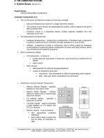
4.5 Block frame size = 16 bytes = 4 doublewords
Number of block frames in cache =
16 KBytes
16 Bytes
= 1024
Number of sets =
Number of block frames
Associativity
=
1024
4
= 256 sets
-21-
Offset
SetTag
20 bits
8 4
Decoder
Comp1
Comp2
Comp3
Comp4
8
20
Set 0
Set 1
Set 255
•
•
•
•
•
•
Set
0
Set
1
Set
255
Tag (20) 4 DWs
Hit
4
Example: doubleword from location ABCDE8F8 is mapped onto: set 143, any
line, doubleword 2:
(1000)A B C D E (1111) (1000)
8 F 8
Set = 143
-22-
4.6
12 bits 10 bits
4.7 A 32-bit address consists of a 21-bit tag field, a 7-bit set field, and a 4-bit word
field. Each set in the cache includes 3 LRU bits and four lines. Each line consists of
4 32-bit words, a valid bit, and a 21-bit tag.
4.8 a. 8 leftmost bits = tag; 5 middle bits = line number; 3 rightmost bits = byte
number
b. slot 3; slot 6; slot 3; slot 21
c. Bytes with addresses 0001 1010 0001 1000 through 0001 1010 0001 1111 are
stored in the cache
d. 256 bytes
e. Because two items with two different memory addresses can be stored in the
same place in the cache. The tag is used to distinguish between them.
-23-
4.9 a. The bits are set according to the following rules with each access to the set:
1. If the access is to L0 or L1, B0 5 1.
2. If the access is to L0, B1 5 1.
3. If the access is to L1, B1 5 0.
4. If the access is to L2 or L3, B0 5 0.
5. If the access is to L2, B2 5 1.
6. If the access is to L3, B2 5 0.
The replacement algorithm works as follows (Figure 4.15): When a line must be
replaced, the cache will first determine whether the most recent use was from
L0 and L1 or L2 and L3. Then the cache will determine which of the pair of
blocks was least recently used and mark it for replacement. When the cache is
initialized or flushed all 128 sets of three LRU bits are set to zero.
b. The 80486 divides the four lines in a set into two pairs (L0, L1 and L2, L3). Bit
B0 is used to select the pair that has been least-recently used. Within each pair,
one bit is used to determine which member of the pair was least-recently used.
However, the ultimate selection only approximates LRU. Consider the case in
which the order of use was: L0, L2, L3, L1. The least-recently used pair is (L2,
L3) and the least-recently used member of that pair is L2, which is selected for
replacement. However, the least-recently used line of all is L0. Depending on
the access history, the algorithm will always pick the least-recently used entry
or the second least-recently used entry.
c. The most straightforward way to implement true LRU for a four-line set is to
associate a two bit counter with each line. When an access occurs, the counter
for that block is set to 0; all counters with values lower than the original value
for the accessed block are incremented by 1. When a miss occurs and the set is
not full, a new block is brought in, its counter is set to 0 and all other counters
are incremented by 1. When a miss occurs and the set is full, the block with
counter value 3 is replaced; its counter is set to 0 and all other counters are
incremented by 1. This approach requires a total of 8 bits.
In general, for a set of N blocks, the above approach requires 2N bits. A
more efficient scheme can be designed which requires only N(N–1)/2 bits. The
scheme operates as follows. Consider a matrix R with N rows and N columns,
and take the upper-right triangular portion of the matrix, not counting the
diagonal. For N = 4, we have the following layout:
R(1,2)
R(1,3)
R(1,4)
R(2,3)
R(2,4)
R(3,4)
When line I is referenced, row I of R(I,J) is set to 1, and column I of R(J,I) is set
to 0. The LRU block is the one for which the row is entirely equal to 0 (for those
bits in the row; the row may be empty) and for which the column is entirely 1
(for all the bits in the column; the column may be empty). As can be seen for N
= 4, a total of 6 bits are required.
-24-
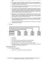
4.10 Block size = 4 words = 2 doublewords; associativity K = 2; cache size = 4048
words; C = 1024 block frames; number of sets S = C/K = 512; main memory = 64K
4 32 bits = 256 Kbytes = 2
18
bytes; address = 18 bits.
Tag Set
Word bits
(6 bits) (9) (2) (1)
Compare
0
Compare
1
Decoder
Set 0
Set 511
•
•
•
Tag (6) 4 words
Set 0
(8 words)
Set 511
(8 words)
•
•
•
word select
4.11 a. Address format: Tag = 20 bits; Line = 6 bits; Word = 6 bits
Number of addressable units = 2
s+w
= 2
32
bytes; number of blocks in main
memory = 2
s
= 2
26
; number of lines in cache 2
r
= 2
6
= 64; size of tag = 20 bits.
b. Address format: Tag = 26 bits; Word = 6 bits
Number of addressable units = 2
s+w
= 2
32
bytes; number of blocks in main
memory = 2
s
= 2
26
; number of lines in cache = undetermined; size of tag = 26
bits.
c. Address format: Tag = 9 bits; Set = 17 bits; Word = 6 bits
Number of addressable units = 2
s+w
= 2
32
bytes; Number of blocks in main
memory = 2
s
= 2
26
; Number of lines in set = k = 4; Number of sets in cache = 2
d
= 2
17
; Number of lines in cache = k 4 2
d
=2
19
; Size of tag = 9 bits.
4.12 a. Because the block size is 16 bytes and the word size is 1 byte, this means there
are 16 words per block. We will need 4 bits to indicate which word we want
out of a block. Each cache line/slot matches a memory block. That means each
cache slot contains 16 bytes. If the cache is 64Kbytes then 64Kbytes/16 = 4096
cache slots. To address these 4096 cache slots, we need 12 bits (212 = 4096).
Consequently, given a 20 bit (1 MByte) main memory address:
Bits 0-3 indicate the word offset (4 bits)
Bits 4-15 indicate the cache slot (12 bits)
Bits 16-19 indicate the tag (remaining bits)
F0010 = 1111 0000 0000 0001 0000
Word offset = 0000 = 0
Slot = 0000 0000 0001 = 001
Tag = 1111 = F
01234 = 0000 0001 0010 0011 0100
Word offset = 0100 = 4
Slot = 0001 0010 0011 = 123
-25-
Tag = 0000 = 0
CABBE = 1100 1010 1011 1011 1110
Word offset = 1110 = E
Slot = 1010 1011 1011 = ABB
Tag = 1100 = C
b. We need to pick any address where the slot is the same, but the tag (and
optionally, the word offset) is different. Here are two examples where the slot
is 1111 1111 1111
Address 1:
Word offset = 1111
Slot = 1111 1111 1111
Tag = 0000
Address = 0FFFF
Address 2:
Word offset = 0001
Slot = 1111 1111 1111
Tag = 0011
Address = 3FFF1
c. With a fully associative cache, the cache is split up into a TAG and a
WORDOFFSET field. We no longer need to identify which slot a memory block
might map to, because a block can be in any slot and we will search each cache
slot in parallel. The word-offset must be 4 bits to address each individual word
in the 16-word block. This leaves 16 bits leftover for the tag.
F0010
Word offset = 0h
Tag = F001h
CABBE
Word offset = Eh
Tag = CABBh
d. As computed in part a, we have 4096 cache slots. If we implement a two -way
set associative cache, then it means that we put two cache slots into one set.
Our cache now holds 4096/2 = 2048 sets, where each set has two slots. To
address these 2048 sets we need 11 bits (211 = 2048). Once we address a set, we
will simultaneously search both cache slots to see if one has a tag that matches
the target. Our 20-bit address is now broken up as follows:
Bits 0-3 indicate the word offset
Bits 4-14 indicate the cache set
Bits 15-20 indicate the tag
F0010 = 1111 0000 0000 0001 0000
Word offset = 0000 = 0
Cache Set = 000 0000 0001 = 001
Tag = 11110 = 1 1110 = 1E
CABBE = 1100 1010 1011 1011 1110
Word offset = 1110 = E
Cache Set = 010 1011 1011 = 2BB
Tag = 11001 = 1 1001 = 19
4.13 Associate a 2-bit counter with each of the four blocks in a set. Initially, arbitrarily
set the four values to 0, 1, 2, and 3 respectively. When a hit occurs, the counter of
the block that is referenced is set to 0. The other counters in the set with values
-26-
originally lower than the referenced counter are incremented by 1; the remaining
counters are unchanged. When a miss occurs, the block in the set whose counter
value is 3 is replaced and its counter set to 0. All other counters in the set are
incremented by 1.
4.14 Writing back a line takes 30 + (7 4 5) = 65 ns, enough time for 2.17 single-word
memory operations. If the average line that is written at least once is written more
than 2.17 times, the write-back cache will be more efficient.
4.15 a. A reference to the first instruction is immediately followed by a reference to the
second.
b. The ten accesses to a[i] within the inner for loop which occur within a short
interval of time.
4.16 Define
C
i
= Average cost per bit, memory level i
S
i
= Size of memory level i
T
i
= Time to access a word in memory level i
H
i
= Probability that a word is in memory i and in no higher-level memory
B
i
= Time to transfer a block of data from memory level (i + 1) to memory level i
Let cache be memory level 1; main memory, memory level 2; and so on, for a total
of N levels of memory. Then
C
s
=
C
i
S
i
i =1
N
1
S
i
i=1
N
1
The derivation of T
s is more complicated. We begin with the result from
probability theory that:
Expected Value of x = i Pr x = 1
[ ]
i =1
N
1
We can write:
T
s
= T
i
H
i
i =1
N
1
We need to realize that if a word is in M
1
(cache), it is read immediately. If it is in
M
2
but not M
1
, then a block of data is transferred from M
2
to M
1
and then read.
Thus:
T
2
= B
1
+
T
1
-27-
Further
T
3
= B
2
+ T
2
= B
1
+ B
2
+ T
1
Generalizing:
T
i
= B
j
+ T
1
j=1
i21
1
So
T
s
= B
j
H
i
( )
j=1
i21
1
i=2
N
1
+ T
1
H
i
i=1
N
1
But
H
i
i =1
N
1
= 1
Finally
T
s
= B
j
H
i
( )
j=1
i21
1
i=2
N
1
+ T
1
4.17 Main memory consists of 512 blocks of 64 words. Cache consists of 16 sets; each set
consists of 4 slots; each slot consists of 64 words. Locations 0 through 4351 in main
memory occupy blocks 0 through 67. On the first fetch sequence, block 0 through
15 are read into sets 0 through 15; blocks 16 through 31 are read into sets 0 through
15; blocks 32-47 are read into sets 0 through 15; blocks 48-63 are read into sets 0
through 15; and blocks 64-67 are read into sets 0 through 3. Because each set has 4
slots, there is no replacement needed through block 63. The last 4 groups of blocks
involve a replacement. On each successive pass, replacements will be required in
sets 0 through 3, but all of the blocks in sets 4 through 15 remain undisturbed.
Thus, on each successive pass, 48 blocks are undisturbed, and the remaining 20
must read in.
Let T be the time to read 64 words from cache. Then 10T is the time to read 64
words from main memory. If a word is not in the cache, then it can only be ready
by first transferring the word from main memory to the cache and then reading the
cache. Thus the time to read a 64-word block from cache if it is missing is 11T.
We can now express the improvement factor as follows. With no cache
Fetch time = (10 passes) (68 blocks/pass) (10T/block) = 6800T
With cache
Fetch time = (68) (11T) first pass
+ (9) (48) (T) + (9) (20) (11T) other passes
= 3160T
Improvement =
6800T
3160T
= 2.15