ASTM D524 Standard Test Method for Ramsbottom Carbon Residue of Petroleum Products
Bạn đang xem bản rút gọn của tài liệu. Xem và tải ngay bản đầy đủ của tài liệu tại đây (287.21 KB, 9 trang )
Designation: D524 − 10
Designation: 14/94
Standard Test Method for
Ramsbottom Carbon Residue of Petroleum Products
1
This standard is issued under the fixed designation D524; the number immediately following the designation indicates the year of
original adoption or, in the case of revision, the year of last revision. A number in parentheses indicates the year of last reapproval. A
superscript epsilon (´) indicates an editorial change since the last revision or reapproval.
This standard has been approved for use by agencies of the Department of Defense.
1. Scope*
1.1 This test method covers the determination of the amount
of carbon residue (
Note 1) left after evaporation and pyrolysis
of an oil, and it is intended to provide some indication of
relative coke-forming propensity. This test method is generally
applicable to relatively nonvolatile petroleum products which
partially decompose on distillation at atmospheric pressure.
This test method also covers the determination of carbon
residue on 10% (V/V) distillation residues (see Section
10).
Petroleum products containing ash-forming constituents as
determined by Test Method
D482, will have an erroneously
high carbon residue, depending upon the amount of ash formed
(
Notes 2 and 3).
NOTE 1—The term carbon residue is used throughout this test method
to designate the carbonaceous residue formed during evaporation and
pyrolysis of a petroleum product. The residue is not composed entirely of
carbon, but is a coke which can be further changed by pyrolysis. The term
carbon residue is continued in this test method only in deference to its
wide common usage.
N
OTE 2—Values obtained by this test method are not numerically the
same as those obtained by Test Method
D189, or Test Method D4530.
Approximate correlations have been derived (see
Fig. X2.1) but need not
apply to all materials which can be tested because the carbon residue test
is applicable to a wide variety of petroleum products. The Ramsbottom
Carbon Residue test method is limited to those samples that are mobile
below 90°C.
N
OTE 3—In diesel fuel, the presence of alkyl nitrates such as amyl
nitrate, hexyl nitrate, or octyl nitrate, causes a higher carbon residue value
than observed in untreated fuel, which can lead to erroneous conclusions
as to the coke-forming propensity of the fuel. The presence of alkyl nitrate
in the fuel can be detected by Test Method
D4046.
N
OTE 4—The test procedure in Section 10 is being modified to allow
the use of a 100–mL volume automated distillation apparatus. No
precision data is available for the procedure at this time, but a round robin
is being planned to develop precision data. The 250–mL volume bulb
distillation method described in Section
10 for determining carbon residue
on a 10 % distillation residue is considered the referee test.
1.2 The values stated in SI units are to be regarded as
standard. No other units of measurement are included in this
standard.
1.3 WARNING—Mercury has been designated by many
regulatory agencies as a hazardous material that can cause
central nervous system, kidney and liver damage. Mercury, or
its vapor, may be hazardous to health and corrosive to
materials. Caution should be taken when handling mercury and
mercury containing products. See the applicable product Ma-
terial Safety Data Sheet (MSDS) for details and EPA’s
website— addi-
tional information. Users should be aware that selling mercury
and/or mercury containing products into your state or country
may be prohibited by law.
1.4 This standard does not purport to address all of the
safety concerns, if any, associated with its use. It is the
responsibility of the user of this standard to establish appro-
priate safety and health practices and determine the applica-
bility of regulatory limitations prior to use.
2. Referenced Documents
2.1 ASTM Standards:
2
D86 Test Method for Distillation of Petroleum Products at
Atmospheric Pressure
D189 Test Method for Conradson Carbon Residue of Petro-
leum Products
D482 Test Method for Ash from Petroleum Products
D4046 Test Method for Alkyl Nitrate in Diesel Fuels by
Spectrophotometry
D4057 Practice for Manual Sampling of Petroleum and
Petroleum Products
D4175 Terminology Relating to Petroleum, Petroleum Prod-
ucts, and Lubricants
D4177 Practice for Automatic Sampling of Petroleum and
Petroleum Products
1
This test method is under the jurisdiction of ASTM Committee D02 on
Petroleum Products and Lubricants and is the direct responsibility of Subcommittee
D02.06 on Analysis of Lubricants.
Current edition approved July 1, 2010. Published July 2010. Originally approved
in 1939. Last previous edition approved in 2009 as D524–09.
In the IP, this test method is under the jurisdiction of the Standardization
Committee. DOI: 10.1520/D0524-10.
2
For referenced ASTM standards, visit the ASTM website, www.astm.org, or
contact ASTM Customer Service at For Annual Book of ASTM
Standards volume information, refer to the standard’s Document Summary page on
the ASTM website.
*A Summary of Changes section appears at the end of this standard
Copyright © ASTM International, 100 Barr Harbor Drive, PO Box C700, West Conshohocken, PA 19428-2959. United States
1
Copyright by ASTM Int'l (all rights reserved); Sat Oct 19 11:53:21 EDT 2013
Downloaded/printed by
Pontifcia Universidade Catlica do Rio Grande do Sul pursuant to License Agreement. No further reproductions authorized.
D4530 Test Method for Determination of Carbon Residue
(Micro Method)
E1 Specification for ASTM Liquid-in-Glass Thermometers
E133 Specification for Distillation Equipment
2.2 Energy Institute Standard:
3
Appendix AP-A Specifications—IP Thermometers
3. Terminology
3.1 Definitions:
3.1.1 carbon residue, n—the residue formed by evaporation
and thermal degradation of a carbon containing material.
D4175
3.1.1.1 Discussion—The residue is not composed entirely of
carbon but is a coke that can be further changed by carbon
pyrolysis. The term carbon residue is retained in deference to
its wide common usage.
4. Summary of Test Method
4.1 The sample, after being weighed into a special glass
bulb having a capillary opening, is placed in a metal furnace
maintained at approximately 550°C. The sample is thus
quickly heated to the point at which all volatile matter is
evaporated out of the bulb with or without decomposition
while the heavier residue remaining in the bulb undergoes
cracking and coking reactions. In the latter portion of the
heating period, the coke or carbon residue is subject to further
slow decomposition or slight oxidation due to the possibility of
breathing air into the bulb. After a specified heating period, the
bulb is removed from the bath, cooled in a desiccator, and
again weighed. The residue remaining is calculated as a
percentage of the original sample, and reported as Ramsbottom
carbon residue.
4.2 Provision is made for determining the proper operating
characteristics of the furnace with a control bulb containing a
thermocouple, which must give a specified time-temperature
relationship.
5. Significance and Use
5.1 The carbon residue value of burner fuel serves as a
rough approximation of the tendency of the fuel to form
deposits in vaporizing pot-type and sleeve-type burners. Simi-
larly, provided alkyl nitrates are absent (or if present, provided
the test is performed on the base fuel without additive) the
carbon residue of diesel fuel correlates approximately with
combustion chamber deposits.
5.2 The carbon residue value of motor oil, while at one time
regarded as indicative of the amount of carbonaceous deposits
a motor oil would form in the combustion chamber of an
engine, is now considered to be of doubtful significance due to
the presence of additives in many oils. For example, an
ash-forming detergent additive can increase the carbon residue
value of an oil yet will generally reduce its tendency to form
deposits.
5.3 The carbon residue value of gas oil is useful as a guide
in the manufacture of gas from gas oil, while carbon residue
values of crude oil residuum, cylinder and bright stocks, are
useful in the manufacture of lubricants.
6. Apparatus
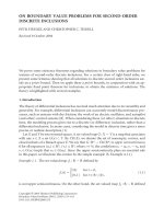
6.1 Glass Coking Bulb, of heat-resistant glass conforming to
the dimensions and tolerances shown in
Fig. 1. Prior to use,
check the diameter of the capillary to see that the opening is
greater than 1.5 and not more than 2.0 mm. Pass a 1.5-mm
diameter drill rod through the capillary and into the bulb;
attempt to pass a 2.0-mm diameter drill rod through the
capillary. Reject bulbs that do not permit the insertion of the
smaller rod and those whose capillaries are larger than the
larger rod.
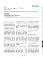
6.2 Control Bulb, stainless steel, containing a thermocouple
and conforming to the dimensions and tolerances shown in
Fig.
2
, for use in determining compliance of furnace characteristics
with the performance requirements (Section
7). The control
bulb shall be provided with a dull finish, as specified in Fig. 2,
and must not be polished thereafter. A polished bulb has
different heating characteristics from one with a dull finish. A
suitable thermocouple pyrometer for observing true tempera-
ture within 61°C is also required.
6.3 Sample Charging Syringe, 5 or 10-mL glass hypodermic
(
Note 5), fitted with a No. 17 needle (1.5 mm in outside
diameter) or No. 0 serum needle (1.45 to 1.47 mm in outside
diameter) for transfer of the sample to the glass coking bulb.
NOTE 5—A syringe having a needle that fits on the ground-glass tip of
the syringe is not recommended, as it may be blown off when pressure is
applied to the syringe plunger. The Luer-Lok type syringes are more
satisfactory, as the needle locks on the bottom of the syringe barrel, and
cannot be blown off by pressure.
6.4 Metal Coking Furnace of solid metal, having coking
bulb wells 25.45 6 0.1 mm in internal diameter and 76 mm
deep to the center of the well bottom, with suitable arrange-
ments for heating to a uniform temperature of 550°C. The
bottom of the well shall be hemispherical to accommodate the
bottom of the glass coking bulb. Do not cast or otherwise form
3
IP Standard Methods for Analysis and Testing of Petroleum and Related
Products, 1998. Available from Energy Institute, 61 New Cavendish St., London,
WIG 7AR, U.K.
NOTE 1—All dimensions are in millimetres.
FIG. 1 Glass Coking Bulb
D524 − 10
2
Copyright by ASTM Int'l (all rights reserved); Sat Oct 19 11:53:21 EDT 2013
Downloaded/printed by
Pontifcia Universidade Catlica do Rio Grande do Sul pursuant to License Agreement. No further reproductions authorized.
the furnace with unnecessary voids which will impede heat
transfer. If a molten metal furnace is used, provide it with a
suitable number of bulb wells, the internal dimensions of
which correspond to the internal dimensions of holes in the
solid metal furnace. The bulb wells shall be immersed in the
molten metal to leave not more than 3 mm of the bulb well
exposed above the molten metal at operating temperatures.
NOTE 6—Ramsbottom coke furnaces now in use can have dimensional
differences from those given in
6.4; however, it is essential that new
furnaces obtained after the adoption of this test method conform to the
requirements outlined in
6.4. A description of one type of furnace which
has been found to be satisfactory is given in
Appendix X1.
6.5 Temperature-Measuring Devices—A removable iron-
constantan thermocouple with a sensitive pyrometer, or other
suitable temperature-indicating device, located centrally near
the bottom portion of the furnace and arranged to measure the
temperature of the furnace so that the performance tests
specified in Section
7 can be obtained. It is desirable to protect
the temperature-indicating device with a quartz or thin metal
sheath when a molten bath is used.
NOTE 7—It is good practice to calibrate the thermocouple or other
temperature-measuring device against a standard thermocouple or refer-
ence standards about once a week, when the furnace is in constant use, the
actual frequency depending on experience.
7. Checking Performance of Apparatus
7.1 Periodically check the performance of the furnace and
temperature-measuring devices as described in
7.1.1-7.1.3 to
make certain that as used they conform to the requirements of
the method. Consider the furnace as having standard perfor-
mance, and use it with any degree of loading, when the
operating requirements described for each coking bulb well are
met, while the bath is fully loaded as well as singly loaded. Use
only a furnace that has successfully passed the performance or
control tests given in this section.
7.1.1 Thermocouple—At least once every 50 h of use of the
control bulb, calibrate the thermocouple in the control bulb
against a standard thermocouple.
NOTE 8—In use at the high temperature of the test, iron-constantan
thermocouples oxidize and their calibration curves change.
7.1.2 Fully Loaded Furnace—When the furnace tempera-
ture is within a previously chosen 2°C temperature range
(which range is to be used thereafter with that particular
furnace for both standardization and routine operation) and
within the general range 550 6 5°C, insert the control bulb in
one well and, within 15 s, insert in each of the other wells a
glass coking bulb containing 4 6 0.1 g of a viscous neutral
petroleum lubricating oil with a viscosity within the SAE 30
range or 60 to 100 mm
2
/s (cSt) at 40°C. With a suitably
accurate potentiometer or millivoltmeter (sensitive to 1°C or
less), observe the temperature rise in the control bulb at 1-min
intervals for 20 min. If the temperature in the control bulb
reaches 547°C in not less than 4 and not more than 6 min from
the instant of its insertion in the furnace, and remains within
the range 550 6 3°C for the remaining portion of the 20-min
test, consider that particular coking bulb well suitable for use
as a standard performance well when the furnace is used fully
loaded. Inspect each well in similar fashion with the furnace
fully loaded each time.
7.1.3 Singly Loaded Furnace—When the furnace tempera-
ture is within a previously chosen 2°C temperature range
(which range is to be used thereafter with that particular
furnace for both standardization and routine operation) and
within the general range 550 6 5°C, insert the control bulb in
one well, with the remaining wells unoccupied. With a suitably
accurate potentiometer or millivoltmeter (sensitive to 1°C or
less), observe the temperature rise in the control bulb at 1-min
intervals for 20 min. If the temperature in the control bulb
reaches 547°C in not less than 4 and not more than 6 min from
the instant of its insertion in the furnace, and remains within
the range 550 6 3°C for the remaining portion of the 20-min
test, consider that particular coking bulb well suitable for use
as a standard performance well when only a single test is
made. Inspect each well in similar fashion with the furnace
singly loaded each time.
NOTE 9—It is possible that not all of the wells in old furnaces will meet
the requirements when fully loaded and singly loaded; and, when this is
the case, inspect each well for any degree of furnace loading which may
be used. For example, when not more than three wells of a six-well
furnace can be used at any one time, the three wells to be used should be
chosen from the performance data obtained with fully loaded and singly
loaded furnaces. Then each of the three wells should be inspected for triple
loading, two of the wells for double loading, and one for single loading.
Use the wells tested and no others in applying the test procedure.
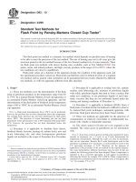
N
OTE 10—In sampling oils containing sediment (for example, used
oils), it is important to make the transfer of sample in the shortest possible
time to avoid segregation of the sediment. Samples containing sediment
which settles quickly after stirring can be placed in the coking bulbs more
expeditiously by using an arrangement such as that shown in
Fig. 3. This
sampling device consists of a three-way 2-mm stopcock to which have
been fused two lengths of capillary tubing (1.5 mm in inside diameter).
Connect the third leg of the stopcock by means of pressure tubing to a
vacuum line. Secure the glass coking bulb to the short arm of capillary
tubing by a 25-mm length of rubber hose, taking care that the capillary of
NOTE 1—All dimensions are in millimetres.
FIG. 2 Control Bulb
D524 − 10
3
Copyright by ASTM Int'l (all rights reserved); Sat Oct 19 11:53:21 EDT 2013
Downloaded/printed by
Pontifcia Universidade Catlica do Rio Grande do Sul pursuant to License Agreement. No further reproductions authorized.
the glass bulb is butted up against the capillary tubing. Immerse the long
end of the capillary tubing in the sample. After evacuating the coking bulb,
manipulate the stopcock to cause the stirred sample to flow freely into the
bulb through the two lengths of capillary tubing. It is necessary to use
tubing with the same size capillary as that in the neck of the coking bulb
to prevent accumulation of any sediment during transfer.
8. Sampling
8.1 For sampling techniques see Practice D4057 or Practice
D4177.
9. Procedure
9.1 Place a new glass coking bulb (
Note 12) in the coking
furnace at 550°C for about 20 min to decompose any foreign
organic matter and to remove water. Place in a closed desic-
cator over a suitable desiccant, such as a desiccant containing
CaCl
2
or CaSO
4
, for 20 to 30 min, and then weigh to the
nearest 0.1 mg.
NOTE 11—Do not reuse a glass coking bulb, as unpredictable results are
sometimes obtained in such cases. For routine testing, new bulbs can be
used without pre-ignition provided they are visibly free from particles or
other contamination. Such bulbs, at least, should be heated in an oven to
150°C, placed in a desiccator, and then weighed.
N
OTE 12—On making a test, it is important to adhere rigorously to the
temperature conditions chosen for Section
7; for example, if the bath was
at a temperature of 553 6 1°C when inserting the control bulb, then it is
necessary to use similar temperature conditions in the coking test. When
maintained in normal operation, the temperature of an electrically heated
furnace with automatic controls will generally fluctuate within a specific
temperature range. Therefore, when making a coking test, it is generally
important that the test bulbs be inserted when the furnace is at the same
temperature or at the same position in the temperature cycle as it was
when the inspection test was started, unless it has been proven that the
temperature variations are inappreciable.
9.2 Shake thoroughly the sample to be tested, first heating to
50° 6 10°C for 0.5 h when necessary to reduce its viscosity.
Immediately following the heating and shaking, strain the
sample through a 100-mesh wire screen. By means of a
hypodermic syringe or the device shown in
Fig. 3 introduce
into the coking bulb an amount of sample as indicated in Table
1
. Make sure that no oil remains on the exterior surface or on
the inside of the neck of the bulb. Reweigh the bulb and
contents to the nearest milligram. If the sample foams or
spatters, repeat the test using the next smaller sample size listed
in
Table 1. In reporting the results, include the size when such
small samples are used. If difficulty is encountered in loading
very viscous or asphaltic samples of any size into the glass
coking bulb, the apparatus shown in
Fig. X1.2 can be used.
9.3 Place the coking bulb in a standard performance well
with the furnace at the checking temperature (
Note 12), and
allow to remain for 20 6 2 min. Remove the bulb with metal
tongs, the tips of which have just been heated. Duplicate the
furnace and bulb conditions used when standardizing that bulb
well (Section
7 and Note 9). If there is appreciable loss of oil
from frothing, discard the test and repeat the determination
using a smaller sample (
Note 13).
NOTE 13—Frothing can be due to water which can be removed by
heating gently in a vacuum and sweeping out the vapor with nitrogen prior
to filling the bulb.
9.4 After removal, cool the bulb in a desiccator under the
same conditions (including time for weighing) used before
filling the bulb (
9.2). When removing the bulb from the
desiccator, examine it to make sure there are no foreign
particles adhering to the bulb; if any are found, as black
particles sometimes are on the capillary neck, brush them off
with a piece of sized paper or camel’s hair brush. Weigh to the
nearest 0.1 mg. Discard the used glass coking bulb.
NOTE 14—In studies of oil characteristics, useful information can often
be gleaned from a simple visual examination of the coking bulb after the
test. Thus, significance can be attached to noting, with the results, such
findings as: coke more or less fills the bulb; liquid material is present,
either as limpid residue or drops; the residue is not black and flaky, but is
colored and pulverulent (presumably from presence of inorganic materi-
als).
10. Procedure for Carbon Residue on 10 % (V/V)
Distillation Residue
10.1 This procedure is applicable to middle distillate mate-
rials, such as ASTM No. 1 and No. 2 fuel oils.
10.2 A distillation analysis using either a 100 or 200-mL
starting volume is required in order to collect a sufficient
amount of the 10 % (V/V) residue needed in this analysis. For
NOTE 1—All dimensions are in millimetres (1 in. = 25 mm).
FIG. 3 Sampling Device
TABLE 1 Sample Sizes
Ramsbottom Carbon
Residue, %
Sample Size, g
Less than 6.0 4.0 ± 0.1
6.0to14.0 1.0±0.1
14.1 to 20.0 0.5 ± 0.1
D524 − 10
4
Copyright by ASTM Int'l (all rights reserved); Sat Oct 19 11:53:21 EDT 2013
Downloaded/printed by
Pontifcia Universidade Catlica do Rio Grande do Sul pursuant to License Agreement. No further reproductions authorized.
a 100-mL distillation, assemble the distillation apparatus de-
scribed in either Test Method
D86 or Specification E133. Use
a distillation flask with a 125-mL bulb volume, a flask support
board with a 50-mm diameter opening, and a graduated
cylinder with a 100-mL capacity. For a 200-mL distillation,
assemble the distillation apparatus described in Specification
E133, using flask D (250-mL bulb volume), flask support board
with 50-mm diameter opening, and graduated cylinder C
(200-mL capacity). A thermometer is not required, but the use
of the ASTM High Distillation Thermometer 8F or 8C, as
prescribed in Specification
E1, or the IP High Distillation
Thermometer 6C, as prescribed in Specifications—IP Ther-
mometers, is recommended.
10.3 Depending upon which distillation flask is used, place
either 100 or 200 mL of sample (as measured at ambient
temperature) into the distillation flask that is held at a tempera-
ture between 13°C and ambient. Maintain the condenser bath
temperature between 0 and 60°C to provide a sufficient
temperature differential for sample condensation. Avoid any
solidification of waxy material in the condenser tube. Place,
without cleaning, the cylinder which was used to measure the
sample under the condenser tube so that the tip of the
condenser does not touch the wall of the cylinder. The receiver
temperature shall be maintained at the same temperature
(within 6 3°C) as when the sample was taken at the start of the
test in order to obtain an accurate volume measurement in the
receiving flask.
10.4 Apply the heat to the flask at a uniform rate so
regulated that the first drop of condensate exits from the
condenser between 10 and 15 min (for 200-mL samples) or
between 5 and 15 min (for 100-mL samples) after initial
application of heat. If a receiving cylinder deflector is not being
used, immediately move the receiving cylinder so that the tip
of the condenser tube touches the inner wall of the cylinder
after the first drop falls. Then regulate the heat so that the
distillation proceeds at a uniform rate of 8 to 10 mL/min (for
200-mL samples) or 4 to 5 mL/min (for 100-mL samples). For
200-mL samples, continue the distillation until approximately
178 mL of distillate has been collected, and then discontinue
heating and allow the condenser to drain until 180 mL (90 %
(V/V) of the charge to the flask) has been collected in the
cylinder. For 100-mL samples, continue the distillation until
approximately 88 mL of distillate has been collected, and then
discontinue heating and allow the condenser to drain until
90 mL (90 % V/V) of the charge to the flask) has been collected
in the cylinder.
10.5 Catch final drainage, if any, by immediately replacing
the cylinder with a suitable container, such as a small Erlen-
meyer flask. Add to this container, while still warm, the
distillation residue left in the distilling flask, and mix well. The
contents of the container then represents a 10 % (V/V)
distillation residue from the original product.
10.6 While the distillation residue is warm enough to flow
freely, place 4.0 6 0.1 g of it into the previously weighed
coking bulb. A hypodermic syringe provides a convenient
means of performing this operation. After cooling, weigh the
bulb and contents to the nearest 1 mg, and carry out the carbon
residue test in accordance with the procedure described in
Section 9.
10.7 Report the percentage of carbon residue as the Rams-
bottom carbon residue on 10 % distillation residue.
11. Calculation and Report
11.1 Calculate the carbon residue of the sample or of the
10 % distillation residue as follows:
Carbon residue 5
~
A 3100
!
/W (1)
where:
A = mass of carbon residue, g, and
W = mass of sample, g.
11.2 Report the value obtained as Ramsbottom carbon
residue, percent or as Ramsbottom carbon residue on 10 %
distillation residue, percent.
12. Precision and Bias
4
12.1 The precision of this test method as determined by
statistical examination of interlaboratory results is as follows:
12.1.1 Repeatability—The difference between two test re-
sults, obtained by the same operator with the same apparatus
under constant operating conditions on identical test material
would, in the long run, in the normal and correct operation of
the test method, exceed the values shown in
Fig. 4 only in one
case in twenty.
12.1.2 Reproducibility—The difference between two single
and independent results obtained by different operators work-
ing in different laboratories on identical test material would, in
the long run, in the normal and correct operation of the test
method, exceed the values shown in
Fig. 4 only in one case in
twenty.
NOTE 15—Precision is based on data developed using inch-pound units.
See Test Method D524.
12.2 Bias—This test method is empirical and no statement
of bias can be made.
13. Keywords
13.1 carbon residue; petroleum products; Ramsbottom
4
Supporting data have been filed at ASTM International Headquarters and may
be obtained by requesting Research Report RR:D02-1228.
D524 − 10
5
Copyright by ASTM Int'l (all rights reserved); Sat Oct 19 11:53:21 EDT 2013
Downloaded/printed by
Pontifcia Universidade Catlica do Rio Grande do Sul pursuant to License Agreement. No further reproductions authorized.
APPENDIXES
(Nonmandatory Information)
X1. RAMSBOTTOM COKING FURNACE
X1.1 The greatest difficulty in achieving satisfactory preci-
sion for this test method is to obtain a uniformly operating
furnace. The type of furnace described below meets the
performance characteristics prescribed in Section
7.
X1.2 Solid Metal Furnace
5
—A solid metal furnace can be
constructed as illustrated in
Fig. X1.1. It can be constructed of
cast iron or other suitable metal for use under the high-
temperature conditions which are employed in this test method.
It is desirable to cast the metal without any unnecessary voids.
Use of a substantial mass of metal for the block avoids the
requirement for an excessive amount of electrical heating
which could cause wide fluctuations in block temperature
unless very sensitive controls were used.
X1.3 Coking Bulb Filling Device—The glass coking bulb
filling device as shown in
Fig. X1.2 has been found satisfactory
for use with any mobile liquids that are too viscous to be
handled at room temperature. The illustrated stand is made of
3 mm brass plate and constructed to hold five 10-mL syringes.
For convenience, the stand can be modified to hold any number
of syringes of either the 5 or 10-mL type.
X1.3.1 Warm the sample to be tested until it is fluid, place
a coking bulb in position under the syringe and remove the
plunger of the syringe from the barrel. Pour a representative
portion of the sample into the barrel of the syringe, lubricate
the plunger with one or two drops of white oil and replace in
the barrel. Then place the loaded syringe in the rack as shown,
with the spring-loaded clip fitted over the plunger head and
with the tip of the needle extending into the bulb. Place the
entire assembly in an oven maintained at the lowest tempera-
ture that will permit the sample to flow sufficiently to load the
bulb.
X1.3.2 As soon as sufficient sample has been forced into the
coking bulb, remove and weigh the bulb and its contents and
proceed as described in
9.3. Remove the assembled apparatus
from the oven as soon as possible as extended heating periods
may alter the carbon residue value of the sample.
5
The sole source of supply of the apparatus known to the committee at this time
is Precision Scientific Co., 3737 W. Cortland St., Chicago, IL 60647. If you are
aware of alternative suppliers, please provide this information to ASTM Headquar-
ters. Your comments will receive careful consideration at a meeting of the
responsible technical committee,
1
which you may attend.
Log r = 0.75238 log x + 0.23682 (log x)
2
- 1.06940
Log R = 0.78907 log x + 0.19014 (log x)
2
- 0.85333
x = average of results being compared
FIG. 4 Precision Data
D524 − 10
6
Copyright by ASTM Int'l (all rights reserved); Sat Oct 19 11:53:21 EDT 2013
Downloaded/printed by
Pontifcia Universidade Catlica do Rio Grande do Sul pursuant to License Agreement. No further reproductions authorized.
FIG. X1.1 Solid Metal Furnace
FIG. X1.2 Coking Bulb Filling Device
D524 − 10
7
Copyright by ASTM Int'l (all rights reserved); Sat Oct 19 11:53:21 EDT 2013
Downloaded/printed by
Pontifcia Universidade Catlica do Rio Grande do Sul pursuant to License Agreement. No further reproductions authorized.
X2. INFORMATION CONCERNING CORRELATION OF CARBON RESIDUE RESULTS DETERMINED BY TEST METHODS
D189 AND D524
X2.1 No exact correlation of the results obtained by the two
test methods exists because of the empirical nature of the two
tests. However, an approximate correlation (
Fig. X2.1) has
been derived from the cooperative testing by ASTM Commit-
tee D02 of 18 representative petroleum products and confirmed
by further data on about 150 samples which were not tested
cooperatively. Test results by both test methods on unusual
types of petroleum products may not fall near the correlation
line of
Fig. X2.1.
X2.2 Caution should be exercised in the application of this
relation to samples of low carbon residues.
NOTE 1—All dimensions are in millimetres.
FIG. X2.1 Correlation Data
D524 − 10
8
Copyright by ASTM Int'l (all rights reserved); Sat Oct 19 11:53:21 EDT 2013
Downloaded/printed by
Pontifcia Universidade Catlica do Rio Grande do Sul pursuant to License Agreement. No further reproductions authorized.
SUMMARY OF CHANGES
Subcommittee D02.06 has identified the location of selected changes to this standard since the last issue
(D524–09) that may impact the use of this standard.
(1) Updated
Fig. 2.
ASTM International takes no position respecting the validity of any patent rights asserted in connection with any item mentioned
in this standard. Users of this standard are expressly advised that determination of the validity of any such patent rights, and the risk
of infringement of such rights, are entirely their own responsibility.
This standard is subject to revision at any time by the responsible technical committee and must be reviewed every five years and
if not revised, either reapproved or withdrawn. Your comments are invited either for revision of this standard or for additional standards
and should be addressed to ASTM International Headquarters. Your comments will receive careful consideration at a meeting of the
responsible technical committee, which you may attend. If you feel that your comments have not received a fair hearing you should
make your views known to the ASTM Committee on Standards, at the address shown below.
This standard is copyrighted by ASTM International, 100 Barr Harbor Drive, PO Box C700, West Conshohocken, PA 19428-2959,
United States. Individual reprints (single or multiple copies) of this standard may be obtained by contacting ASTM at the above
address or at 610-832-9585 (phone), 610-832-9555 (fax), or (e-mail); or through the ASTM website
(www.astm.org). Permission rights to photocopy the standard may also be secured from the ASTM website (www.astm.org/
COPYRIGHT/).
D524 − 10
9
Copyright by ASTM Int'l (all rights reserved); Sat Oct 19 11:53:21 EDT 2013
Downloaded/printed by
Pontifcia Universidade Catlica do Rio Grande do Sul pursuant to License Agreement. No further reproductions authorized.
![Standard Test Method for Compressive Strength of Hydraulic Cement Mortars (Using 2-in. or [50-mm] Cube Specimens)](https://media.store123doc.com/images/document/14/rc/yi/medium_yil1395845738.jpg)