guide for measuring, mixing, transporting, and placing concrete
Bạn đang xem bản rút gọn của tài liệu. Xem và tải ngay bản đầy đủ của tài liệu tại đây (833.37 KB, 41 trang )
ACI 304R-00 supersedes ACI 304R-89 and became effective January 10, 2000.
Copyright 2000, American Concrete Institute.
All rights reserved including rights of reproduction and use in any form or by any
means, including the making of copies by any photo process, or by electronic or
mechanical device, printed, written, or oral, or recording for sound or visual
reproduction or for use in any knowledge or retrieval system or device, unless
permission in writing is obtained from the copyright proprietors.
304R-1
ACI Committee Reports, Guides, Standard Practices, and Commentaries
are intended for guidance in planning, designing, executing, and inspecting
construction. This document is intended for the use of individuals who
are competent to evaluate the significance and limitations of its
content and recommendations and who will accept responsibility for
the application of the material it contains. The American Concrete
Institute disclaims any and all responsibility for the stated principles. The
Institute shall not be liable for any loss or damage arising therefrom.
Reference to this document shall not be made in contract documents. If
items found in this document are desired by the Architect/Engineer to be
a part of the contract documents, they shall be restated in mandatory lan-
guage for incorporation by the Architect/Engineer.
This guide presents information on the handling, measuring, and batching
of all the materials used in making normalweight, lightweight structural,
and heavyweight concrete. It covers both weight and volumetric
measuring; mixing in central mixture plants and truck mixers; and concrete
placement using buckets, buggies, pumps, and conveyors. Underwater
concrete placement and preplaced aggregate concrete are also covered in
this guide, as well as procedures for achieving good quality concrete in
completed structures.
Keywords
: batching; conveying; heavyweight concretes; lightweight
concretes; materials handling; mixing; placing; preplaced aggregate concrete;
pumped concrete; tremie concrete; volumetric measuring; continuous mixing.
CONTENTS
Chapter 1—Introduction, p. 304R-2
1.1—Scope
1.2—Objective
1.3—Other considerations
Chapter 2—Control, handling, and storage of
materials, p. 304R-3
2.1—General considerations
2.2—Aggregates
2.3—Cement
2.4—Ground slag and pozzolans
2.5—Admixtures
Guide for Measuring, Mixing, Transporting,
and Placing Concrete
Reported by ACI Committee 304
ACI 304R-00
Neil R. Guptill
Chairman
David J. Akers John C. King Kenneth L. Saucier
Casimir Bognacki Gary R. Mass James M. Shilstone, Jr.
James L. Cope Patrick L. McDowell Ronald J. Stickel
Michael R. Gardner Dipak T. Parekh William X. Sypher
Daniel J. Green Roger J. Phares J.A. Tony Tinker
Brian Hanlin James S. Pierce Robert E. Tobin
Terence C. Holland Paul E. Reinhart Joel B. Tucker
Thomas A. Johnson Royce J. Rhoads Kevin Wolf
2.6—Water and ice
2.7—Fiber reinforcement
Chapter 3—Measurement and batching, p. 304R-6
3.1—General requirements
3.2—Bins and weigh batchers
3.3—Plant type
3.4—Cementitious materials
3.5—Water and ice measurement
3.6—Measurement of admixtures
3.7—Measurement of materials for small jobs
3.8—Other considerations
Chapter 4—Mixing and transporting, p. 304R-9
4.1—General requirements
4.2—Mixing equipment
4.3—Central-mixed concrete
4.4—Truck-mixed concrete
4.5—Charging and mixing
4.6—Mixture temperature
4.7—Discharging
4.8—Mixer performance
4.9—Maintenance
4.10—General considerations for transporting concrete
4.11—Returned concrete
Chapter 5—Placing concrete, p. 304R-13
5.1—General considerations
5.2—Planning
304R-2
ACI COMMITTEE REPORT
5.3—Reinforcement and embedded items
5.4—Placing
5.5—Consolidation
5.6—Mass concreting
Chapter 6—Forms, joint preparation, and
finishing, p. 304R-19
6.1—Forms
6.2—Joint preparation
6.3—Finishing unformed surfaces
Chapter 7—Preplaced-aggregate concrete,
p. 304R-21
7.1—General considerations
7.2—Materials
7.3—Grout proportioning
7.4—Temperature control
7.5—Forms
7.6—Grout pipe systems
7.7—Coarse aggregate placement
7.8—Grout mixing and pumping
7.9—Joint construction
7.10—Finishing
7.11—Quality control
Chapter 8—Concrete placed under water,
p. 304R-24
8.1—General considerations
8.2—Materials
8.3—Mixture proportioning
8.4—Concrete production and testing
8.5—Tremie equipment and placement procedure
8.6—Direct pumping
8.7—Concrete characteristics
8.8—Precautions
8.9—Special applications
8.10—Antiwashout admixtures
Chapter 9—Pumping concrete, p. 304R-28
9.1—General considerations
9.2—Pumping equipment
9.3—Pipeline and accessories
9.4—Proportioning pumpable concrete
9.5—Field practice
9.6—Field control
Chapter 10—Conveying concrete, p. 304R-30
10.1—General considerations
10.2—Conveyor operation
10.3—Conveyor design
10.4—Types of concrete conveyors
10.5—Field practice
Chapter 11—Heavyweight and radiation-shielding
concrete, p. 304R-33
11.1—General considerations
11.2—Materials
11.3—Concrete characteristics
11.4—Mixing equipment
11.5—Formwork
11.6—Placement
11.7—Quality control
Chapter 12—Lightweight structural concrete,
p. 304R-36
12.1—General considerations
12.2—Measuring and batching
12.3—Mixing
12.4—Job controls
Chapter 13—Volumetric-measuring and
continuous-mixing concrete equipment,
p. 304R-38
13.1—General considerations
13.2—Operations
13.3—Fresh concrete properties
Chapter 14—References, p. 304R-39
14.1—Referenced standards and reports
14.2—Cited references
CHAPTER 1—INTRODUCTION
1.1—Scope
This guide outlines procedures for achieving good results
in measuring and mixing ingredients for concrete, transport-
ing it to the site, and placing it. The first six chapters are gen-
eral and apply to all types of projects and concrete. The
following four chapters deal with preplaced-aggregate con-
crete, underwater placing, pumping, and conveying on belts.
The concluding three chapters deal with heavyweight, radia-
tion-shielding concrete, lightweight concrete, and volumet-
ric-measuring and continuous-mixing concrete equipment.
1.2—Objective
When preparing this guide, ACI Committee 304 followed
this philosophy:
• Progress in improvement of concrete construction is
better served by the presentation of high standards
rather than common practices;
• In many, if not most, cases, practices resulting in the
production and placement of high-quality concrete can
be performed as economically as those resulting in poor
concrete. Many of the practices recommended in this
document improve concrete uniformity as well as qual-
ity, yielding a smoother operation and higher produc-
tion rates, both of which offset potential additional cost;
and
• Anyone planning to use this guide should have a basic
knowledge of the general practices involved in concrete
work. If more specific information on measuring, mix-
ing, transporting, and placing concrete is desired, the
reader should refer to the list of references given at the
end of this document, and particularly to the work of
the U.S. Bureau of Reclamation (1981), the U.S.
Department of Commerce (1966), the Corps of Engi-
neers (1994a), ASTM C 94, ACI 311.1R, and ACI 318.
To portray more clearly certain principles involved in
achieving maximum uniformity, homogeneity, and
quality of concrete in place, figures that illustrate good
and poor practices are also included in this guide.
1.3—Other considerations
All who are involved with concrete work should know the
importance of maintaining the unit water content as low as
possible and still consistent with placing requirements
(Mielenz 1994; Lovern 1966). If the water-cementitious
materials ratio (w/cm) is kept constant, an increase in unit
water content increases the potential for drying-shrinkage
cracking, and with this cracking, the concrete can lose a
portion of its durability and other favorable characteristics,
such as monolithic properties and low permeability.
Indiscriminate addition of water that increases the w/cm
adversely affects both strength and durability.
304R-3MEASURING, MIXING, TRANSPORTING, AND PLACING CONCRETE
The more a form is filled with the right combination of sol-
ids and the less it is filled with water, the better the resulting
concrete will be. Use only as much cement as is required to
achieve adequate strength, durability, placeability, workabil-
ity, and other specified properties. Minimizing the cement
content is particularly important in massive sections subject
to restraint, as the temperature rise associated with the hydra-
tion of cement can result in cracking because of the change
in volume (ACI 207.1R and 207.2R). Use only as much wa-
ter and fine aggregate as is required to achieve suitable work-
ability for proper placement and consolidation by means of
vibration.
CHAPTER 2—CONTROL, HANDLING, AND
STORAGE OF MATERIALS
2.1—General considerations
Coarse and fine aggregates, cement, pozzolans, and chem-
ical admixtures should be properly stored, batched, and han-
dled to maintain the quality of the resulting concrete.
2.2—Aggregates
Fine and coarse aggregates should be of good quality, un-
contaminated, and uniform in grading and moisture content.
Unless this is accomplished through appropriate specifica-
tions (ASTM C 33) and effective selection, preparation, and
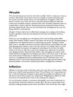
handling of aggregates (Fig. 2.1), the production of uniform
concrete will be difficult (Mielenz 1994; ACI 221R).
2.2.1 Coarse aggregate—The coarse aggregate should be
controlled to minimize segregation and undersized material.
The following sections deal with prevention of segregation
and control of undersized material.
2.2.1.1 Sizes—A practical method of minimizing coarse
aggregate segregation is to separate the material into several
size fractions and batch these fractions separately. As the
range of sizes in each fraction is decreased and the number
of size separations is increased, segregation is further
reduced. Effective control of segregation and undersized
materials is most easily accomplished when the ratio of
maximum-to-minimum size in each fraction is held to not
more than four for aggregates smaller than 1 in. (25 mm) and
to two for larger sizes. Examples of some appropriate
aggregate fraction groupings follow:
Example 1
Sieve designations
No. 8 to 3/8 in. (2.36 to 9.5 mm)
No. 4 to 1 in. (4.75 to 25.0 mm)
3/4 to 1-1/2 in. (19.0 to 37.5 mm)
Example 2
Sieve designations
No. 4 to 3/4 in. (4.75 to 19.0 mm)
3/4 to 1-1/2 in. (19.0 to 37.5 mm)
1-1/2 to 3 in. (37.5 to 75 mm)
3 to 6 in. (75 to 150 mm)
2.2.1.2 Control of undersized material—Undersized
material for a given aggregate fraction is defined as material
that will pass a sieve having an opening 5/6 of the nominal
minimum size of each aggregate fraction (U.S. Bureau of
Reclamation 1981). In Example 2 in Section 2.2.1.1, it would
be material passing the following sieves: No. 5 (4.0 mm), 5/8
in. (16.0 mm), 1-1/4 in. (31.5 mm), and 2-1/2 in. (63 mm). For
effective control of gradation, handling operations that do not
increase the undersized materials in aggregates significantly
before their use in concrete are essential (Fig. 2.1 and 2.2). The
gradation of aggregate as it enters the concrete mixer should
be uniform and within specification limits. Sieve analyses of
coarse aggregate should be made with sufficient frequency to
ensure that grading requirements are met. When two or more
aggregate sizes are used, changes may be necessary in the
proportions of the sizes to maintain the overall grading of the
combined aggregate. When specification limits for grading
cannot be met consistently, special handling methods should
be instituted. Materials tend to segregate during
transportation, so reblending may be necessary. Rescreening
the coarse aggregate as it is charged to the bins at the batch
plant to remove undersized materials will effectively
eliminate undesirable fines when usual storage and handling
methods are not satisfactory. Undersized materials in the
smaller coarse aggregate fractions can be consistently
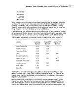
reduced to as low as 2% by rescreening (Fig. 2.2). Although
rescreening is effective in removing undersized particles, it
will not regrade segregated aggregates.
2.2.2 Fine aggregate (sand)—Fine aggregate should be
controlled to minimize variations in gradation, giving special
attention to keeping finer fractions uniform and exercising
care to avoid excessive removal of fines during processing.
If the ratio of fine-to-coarse aggregate is adjusted in accor-
dance with ACI 211.1 recommendations for mixture propor-
tioning, a wide range of fine aggregate gradings can be used
(Tynes 1962). Variations in grading during production of con-
crete should be minimized, however, and the ASTM C 33 re-
quirement that the fineness modulus of the fine aggregate be
maintained within 0.20 of the design value should be met.
Give special attention to the amount and nature of material
finer than the No. 200 screen (75 µm sieve). As stated in
ASTM C 33, if this material is dust of fracture, essentially
free of clay or shale, greater percentages of materials finer
than the No. 200 screen (75 µm sieve) are permissible. If the
reverse is true, however, permissible quantities should be
significantly reduced. The California sand equivalent test is
sometimes used to determine quantitatively the type,
amount, and activity of this fine material (Mielenz 1994;
ASTM D 2419). Excessive quantities of material finer than
the No. 200 screen (75 µm sieve) increase the mixing-water
requirement, rate of slump loss, and drying shrinkage, and
therefore decrease strength.
Avoid blending two sizes of fine aggregate by placing al-
ternate amounts in bins or stockpiles or when loading cars or
trucks. Satisfactory results are achieved when different size
fractions are blended as they flow into a stream from regulat-
ing gates or feeders. A more reliable method of control for a
wide range of plant and job conditions, however, is to sepa-
rate storage, handling, and batching of the coarse and fine
fractions.
2.2.3 Storage—Stockpiling of coarse aggregate should
be kept to a minimum because fines tend to settle and accu-
mulate. When stockpiling is necessary, however, use of
correct methods minimizes problems with fines, segrega-
tion, aggregate breakage, excessive variation in gradation,
and contamination. Stockpiles should be built up in hori-
zontal or gently sloping layers, not by end-dumping.
Trucks, loaders, and dozers, or other equipment should not be
operated on the stockpiles because, in addition to breaking the
aggregate, they frequently track dirt onto the piles (Fig. 2.1).
304R-4
ACI COMMITTEE REPORT
Fig. 2.1—Correct and incorrect methods of handling and storing aggregates.
304R-5MEASURING, MIXING, TRANSPORTING, AND PLACING CONCRETE
Provide a hard base with good drainage to prevent contami-
nation from underlying material. Prevent overlap of the dif-
ferent sizes by suitable walls or ample spacing between piles.
Protect dry, fine aggregate from being separated by the wind
by using tarps or windbreaks. Do not contaminate stockpiles
by swinging aggregate-filled buckets or clam-shovels over
the other piles of aggregate sizes. In addition, fine aggregate
that is transported over wet, unimproved haul roads can be-
come contaminated with clay lumps. The source of this con-
tamination is usually accumulation of mud between the tires
and on mud flaps that is dislodged during dumping of the
transporting unit. Bottom-dump trailers are particularly sus-
ceptible to causing contamination when they drive through
discharged piles. Clay lumps or clay balls can usually be re-
moved from the fine aggregate by placing a scalping screen
over the batch plant bin.
Keep storage bins as full as practical to minimize breakage
and changes in grading as materials are withdrawn. Deposit
materials into the bins vertically and directly over the bin out-
let (Fig. 3.1b). Pay particular attention to the storage of spe-
cial concrete aggregates, including lightweight, high-density,
and architectural-finish aggregates. Contamination of these
materials has compounding effects on other properties of the
concrete in which they are to be used (Chapters 11 and 12).
2.2.4 Moisture control—Ensure, as practically as possible,
a uniform and stable moisture content in the aggregate as
batched. The use of aggregates with varying amounts of free
water is one of the most frequent causes for loss of control of
concrete consistency (slump). In some cases, wetting the
coarse aggregate in the stockpiles or on the delivery belts
may be necessary to compensate for high absorption or to
provide cooling. When this is done, the coarse aggregates
should be dewatered to prevent transfer of excessive free wa-
ter to the bins.
Provide adequate time for drainage of free water from fine
aggregate before transferring it to the batch plant bins. The
storage time required depends primarily on the grading and
particle shape of the aggregate. Experience has shown that a
free-moisture content of as high as 6%, and occasionally as
high as 8%, can be stable in fine aggregate. Tighter controls,
however, may be required for certain jobs. The use of
moisture meters to indicate variations in the moisture of the
fine aggregate as batched, and the use of moisture
compensators for rapid batch weight adjustments, can
minimize the influence of moisture variations in the fine
aggregate (Van Alstine 1955, Lovern 1966).
2.2.5 Samples for test—Samples representing the various
aggregate sizes batched should be obtained as closely as pos-
sible to the point of their introduction into the concrete. The
difficulty in obtaining representative samples increases with
the size of the aggregate. Therefore, sampling devices require
careful design to ensure meaningful test results. Methods of
sampling aggregates are outlined in detail in ASTM D 75.
Maintaining a running average of the results of the five to
10 previous gradation tests, dropping the results of the oldest
and adding the most recent to the total on which the average
is calculated, is good practice. This average gradation can
then be used for both quality control and for proportioning
purposes.
2.3—Cement
All cement should be stored in weathertight, properly
ventilated structures to prevent absorption of moisture.
Storage facilities for bulk cement should include separate
compartments for each type of cement used. The interior of a
cement silo should be smooth, with a minimum bottom slope
of 50 degrees from the horizontal for a circular silo and 55 to
60 degrees for a rectangular silo. Silos should be equipped
with nonclogging air-diffuser flow pads through which small
quantities of dry, oil-free, low-pressure air can be introduced
intermittently at approximately 3 to 5 psi (20 to 35 kPa) to
loosen cement that has settled tightly in the silos. Storage silos
should be drawn down frequently, preferably once per month,
to prevent cement caking.
Each bin compartment from which cement is batched
should include a separate gate, screw conveyor, air slide, ro-
tary feeder, or other conveyance that effectively allows both
constant flow and precise cutoff to obtain accurate batching
of cement.
Make sure cement is transferred to the correct silo by
closely monitoring procedures and equipment. Fugitive dust
should be controlled during loading and transferring.
Bags of cement should be stacked on pallets or similar plat-
forms to permit proper circulation of air. For a storage period
of less than 60 days, stack the bags no higher than 14 layers,
and for longer periods, no higher than seven layers. As an ad-
ditional precaution the oldest cement should be used first.
2.4—Ground slag and pozzolans
Fly ash, ground slag, or other pozzolans should be han-
dled, conveyed, and stored in the same manner as cement.
The bins, however, should be completely separate from ce-
ment bins without common walls that could allow the mate-
rial to leak into the cement bin. Ensure that none of these
materials is loaded into a cement bin on delivery.
2.5—Admixtures
Most chemical admixtures are delivered in liquid form and
should be protected against freezing. If liquid admixtures are
frozen, they should be properly reblended before they are
used in concrete. Manufacturers’ recommendations should
be followed.
Long-term storage of liquid admixtures in vented tanks
should be avoided. Evaporation of the liquid could adversely
affect the performance of the admixture (ACI 212.3R).
Fig. 2.2—Batching plant rescreen arrangement.
304R-6
ACI COMMITTEE REPORT
2.6—Water and ice
Water for concrete production can be supplied from city or
municipal systems, wells, truck wash-out systems, or from
any other source determined to be suitable. If questionable,
the quality of the water should be tested for conformance
with the requirements given in ASTM C 94. Concrete made
with recycled wash water can show variations in strength,
setting time, and response to air-entraining and chemical ad-
mixtures. Recycled wash water may be required to meet
chemical requirements of ASTM C 94. Compensation may
be necessary for the solids in recycled water to maintain
yield and total water content in the concrete.
The water batcher and the water pipes should be leak-free.
If ice is used, the ice facilities, including the equipment for
batching and transporting to the mixer, should be properly
insulated to prevent the ice from melting before it is in the
mixer.
2.7—Fiber reinforcement
Synthetic fiber reinforcement is available in one cubic
yard (one cubic meter) or multicubic yard (cubic meter) in-
crements from most manufacturers. These prepackaged units
should be readily accessible so they can be added directly to
the mixer during the batching process.
Steel fibers are packaged in various sizes; the most com-
mon are 50 or 100 lb (23 or 45 kg) increments. Appropriate
equipment should be used to disperse the fibers into the mix-
er to minimize the potential for the development of fiber
balls. Steel fibers should be stored so that they are not ex-
posed to moisture or other foreign matter. For more informa-
tion on working with steel fibers, see ACI 544.3R.
CHAPTER 3—MEASUREMENT AND BATCHING
3.1—General requirements
3.1.1 Objectives—An important objective in producing
concrete is to achieve uniformity and homogeneity, as indi-
cated by physical properties such as unit weight, slump, air
content, strength, and air-free unit weight of mortar in individ-
ual batches and successive batches of the same mixture pro-
portions (U.S. Department of Reclamation 1981, U.S.
Department of Commerce 1966, Bozarth 1967, ASTM C 94,
Corps of Engineers 1994b). During measurement operations,
aggregates should be handled so that the desired grading is
maintained, and all materials should be measured within the
tolerances acceptable for desired reproducibility of the select-
ed concrete mixture. Another important objective of success-
ful batching is the proper sequencing and blending of the
ingredients (U.S. Department of Commerce 1966, Bozarth
1967). Visual observation of each material being batched is
helpful in achieving this objective.
3.1.2 Tolerances—Most engineering organizations, both
public and private, issue specifications containing detailed re-
quirements for manual, semiautomatic, partially automatic,
and automatic batching equipment for concrete (U.S. Bureau
of Reclamation 1981, Corps of Engineers 1994b, ASTM C 94,
AASHTO 1993). Batching equipment currently marketed
will operate within the usual specified batch-weight toleranc-
es when the equipment is maintained in good mechanical con-
dition. The “Concrete Plant Standards of the Concrete Plant
Manufacturers Bureau” (Concrete Plant Manufacturers Bu-
reau 1996a) and the “Recommended Guide Specifications for
Batching Equipment and Control Systems in Concrete Batch
Plants” (Concrete Plant Manufacturers Bureau 1996b) are fre-
quently used for specifying batching and scale accuracy.
Batching tolerances commonly used are given in Table 3.1.2.
Other commonly used requirements include: beam or
scale divisions of 0.1% of total capacity and batching inter-
lock of 0.3% of total capacity at zero balance (Concrete Plant
Manufacturers Bureau 1996a); quantity of admixture
weighed never to be so small that 0.4% of full scale capacity
exceeds 3% of the required weight; isolation of batching
equipment from plant vibration; protection of automatic con-
trols from dust and weather; and frequent checking and
cleaning of scale and beam pivot points. With good inspec-
tion and plant operation, batching equipment can be expect-
ed to perform consistently within the required tolerances.
3.2—Bins and weigh batchers
Batch plant bins and components should be of adequate
size to accommodate the productive capacity of the plant.
Compartments in bins should separate the various concrete
materials, and the shape and arrangement of aggregate bins
should be conducive to the prevention of aggregate segrega-
tion and breakage. The aggregate bins should be designed so
that material cannot hang up in the bins or spill from one
compartment to another.
Weigh batchers should be charged with easily operated
clamshell or undercut radial-type bin gates. Gates used to
charge semiautomatic and fully automatic batchers should
be power-operated and equipped with a suitable dribble con-
trol to allow the desired weighing accuracy. Weigh batchers
should be accessible for obtaining representative samples,
and they should be arranged to obtain the proper sequencing
and blending of aggregates during charging of the mixer.
Illustrations showing proper and improper design and ar-
rangement of batch plant bins and weigh batchers are given
in Fig. 3.1.
3.3—Plant type
Factors affecting the choice of the batching systems are:
1) size of job; 2) required production rate; and 3) required
Table 3.1.2—Typical batching tolerances
Ingredient
Batch weights greater than 30% of scale capacity Batch weights less than 30% of scale capacity
Individual batching Cumulative batching Individual batching Cumulative batching
Cement and other cementitious
materials
±1% of required mass or ±0.3% of scale capacity,
whichever is greater
Not less than required weight or 4% more than
required weight
Water (by volume or weight), % ±1 Not recommended ±1 Not recommended
Aggregates, % ±2 ±1 ±2
±0.3% of scale capacity or
±3% of required cumula-
tive weight, whichever is
less
Admixtures (by volume or weight), % ±3 Not recommended ±3 Not recommended
304R-7MEASURING, MIXING, TRANSPORTING, AND PLACING CONCRETE
Fig. 3.1—Correct and incorrect methods of batching.
304R-8 ACI COMMITTEE REPORT
standards of batching performance. The production capacity
of a batch plant is determined by a combination of the mate-
rials handling system, bin size, batcher size, and mixer size
and number.
Available weigh batch equipment falls into four general cat-
egories: manual; partially automatic; semiautomatic; and fully
automatic (Concrete Plant Manufacturers Bureau 1996a).
3.3.1 Manual weigh batching—As the name implies, all
operations of weighing and batching of the concrete
ingredients are controlled manually. Manual plants are
acceptable for small jobs having low batching-rate
requirements. As the job size increases, automation of
batching operations is rapidly justified. Attempts to increase
the capacity of manual plants by rapid batching can result in
excessive weighing inaccuracies.
3.3.2 Partially automatic weigh batching—A partially au-
tomatic system consists of a combination of batching con-
trols where at least one of the controls for weighing either
cement or aggregates is either semiautomatic or automatic as
described as follows. Weighing of the remaining materials is
manually controlled and interlocking of the batching system
to any degree is optional. This system can also lack accuracy
when rapid batching is required.
3.3.3 Semiautomatic weigh batching—In this system, aggre-
gate-bin gates for charging are opened by manually operated
buttons or switches. Gates are closed automatically when the
designated weight of material has been delivered. With satis-
factory plant maintenance, the batching accuracy should
meet the tolerances given in Section 3.1.2. The system
should contain interlocks that prevent batcher charging and
discharging from occurring simultaneously. In other words,
when the batcher is being charged, it cannot be discharged,
and when it is being discharged, it cannot be charged. Visual
confirmation of the scale reading for each material being
weighed is essential.
3.3.4 Automatic weigh batching—Automatic weigh batch-
ing of all materials is activated by a single starter switch. In-
terlocks, however, interrupt the batching cycle when the
scale does not return to 0.3% of zero balance or when preset
weighing tolerances detailed in Section 3.1.2 are exceeded.
3.3.4.1 Cumulative automatic weigh batching—
Interlocked sequential controls are required for this type of
batching. Weighing will not begin, and it will be automatically
interrupted when preset tolerances in any of the successive
weighings exceed values such as those given in Section 3.1.2.
The charging cycle will not begin when the batcher discharge
gate is open, and the batcher discharge cycle will not begin
when batcher charging gates are open or when any of the
indicated material weights is not within applicable tolerances.
Presetting of desired batch weights is completed by such
devices as punched cards, digital switches, or rotating dials
and computers. Setting of weights, starting the batch cycle,
and discharging the batch are all manually controlled. Mixture
and batch-size selectors, aggregate moisture meters, manually
controlled fine aggregate moisture compensators, and graphic
or digital devices for recording the batch weight of each
material are required for good plant control (Van Alstine 1955;
Lovern 1966). This type of batching system provides greater
accuracy for high-speed production than either the manual or
semiautomatic systems.
A digital recorder can have a single measuring device for
each scale or a series of measuring devices can record on the
same tape or ticket. This type of recorder should reproduce
the reading of the scale within 0.1% of the scale capacity or
one increment of any volumetric batching device. A digital
batch-documentation recorder should record information on
each material in the mixture along with the concrete mixture
identification, size of batch, and production facility identifi-
cation. Required information can be preprinted, written, or
stamped on the document. The recorder should identify the
load by a batch-count number or a ticket serial number. The
recorder, if interlocked to an automatic batching system,
should show a single indication of all batching systems meet-
ing zero or empty balance interlocks. All recorders should
produce two or more tickets containing the information stat-
ed previously and also leave space for the identification of
the job or project, location of placement, sand moisture con-
tent, delivery vehicle, driver’s signature, purchaser’s repre-
sentative’s signature, and the amount of water added at the
project site.
3.3.4.2 Individual automatic weigh batching—This
system provides separate scales and batchers for each
aggregate size and for every other material batched. The
weighing cycle is started by a single start switch, and
individual batchers are charged simultaneously. Interlocks
for interrupting weighing and discharge cycles when
tolerances are exceeded, mixture selectors, aggregate
moisture meters and compensators, and recorders differ only
slightly from those described for cumulative automatic
batching systems.
3.3.5 Volumetric batching—When aggregates or cementi-
tious materials are batched by volume, it is normally a con-
tinuous operation coupled with continuous mixing.
Volumetric batching and continuous mixing are covered in
Chapter 13.
3.4—Cementitious materials
3.4.1 Batching—For high-volume production requiring
rapid and accurate batching, bulk cementitious materials
should be weighed with automatic, rather than semiautomat-
ic or manual, equipment. All equipment should provide ac-
cess for inspection and permit sampling at any time. The bins
and weigh batchers should be equipped with aeration devic-
es, vibrators, or both to aid in the smooth and complete dis-
charge of the batch. Return to zero and weighing tolerance
interlocks described in Section 3.1.2 should be used. Cement
should be batched separately and kept separate from all in-
gredients before discharging. When both cement and poz-
zolan or slag are to be batched, separate silos should be used.
They can be batched cumulatively, however, if the cement is
weighed first.
3.4.2 Discharging—Effective precautions should be taken
to prevent loss of cementitious materials during mixer charg-
ing. At multiple-stop plants where materials are charged sep-
arately, losses can be minimized by discharging the
cementitious materials through a rubber drop chute. At
one-stop plants, cement and pozzolan can be successfully
charged along with the aggregate through rubber telescopic
dropchutes. For plant mixers, a pipe should be used to dis-
charge the cementitious materials to a point near the center
of the mixer after the water and aggregates have started to
enter the mixer. Proper and consistent sequencing and blend-
ing of the various ingredients into the mixer during the
charging operation will contribute significantly toward the
maintenance of batch-to-batch uniformity and, perhaps, re-
duced mixing time when confirmed by mixer performance
304R-9MEASURING, MIXING, TRANSPORTING, AND PLACING CONCRETE
tests (U.S. Department of Commerce 1966, Gaynor and
Mullarky 1975, ASTM C 94).
3.5—Water and ice measurement
3.5.1 Batching equipment—On large jobs and in central
batching and mixing plants where high-volume production is
required, accurate water and ice measurement can only be ob-
tained by the use of automatic weigh batchers or meters.
Equipment and methods used should, under all operating con-
ditions, be capable of routine measurement within the 1% tol-
erance specified in Section 3.1.2. Tanks or vertical cylinders
with a center-siphon discharge can be permitted as an auxil-
iary part of the weighing, but should not be used as the direct
means of measuring water. For accurate measurement, a dig-
ital gallon (liter) meter should be used. All equipment for
water measurement should be designed for easy calibration
so that accuracy can be quickly verified. Ice-batching equip-
ment should be insulated to avoid melting the ice.
3.5.2 Aggregate moisture determination and compensa-
tion—Measurement of the correct total mixing water de-
pends on knowing the quantity and variation of moisture in
the aggregate (particularly in the fine aggregate) as it is
batched. Aggregate that is not saturated surface dry will ab-
sorb mixture water from the concrete. Fine aggregate mois-
ture meters are frequently used in plants and when properly
maintained do satisfactorily indicate changes in fine aggre-
gate moisture content. Use of moisture meters in fine sizes of
coarse aggregate is also recommended if these materials vary
in moisture content. Moisture meters should be calibrated to
oven-dried samples for optimum consistency of readings.
Moisture meters should be recalibrated monthly or whenever
the slump of the concrete produced is inconsistent.
Moisture-compensating equipment can also be used that
can reproportion water and fine aggregate weights for a
change in aggregate moisture content, with a single setting
adjustment. Compensators are usually used on the fine ag-
gregate, but occasionally are also used on the small coarse
aggregate size fractions. The moisture setting on the com-
pensators is made manually with calibration dials, buttons,
or levers. The use of moisture compensators is recommend-
ed when used in conjunction with calibrated moisture meters
or regularly performed conventional moisture-control tests.
Under these conditions, compensators can be useful tools for
maintaining satisfactory control of the fine aggregate and the
mixing water content.
Most computer-controlled batching systems now have
software that interlocks moisture meters or compensating
equipment with the measuring of fine aggregate and water.
Readings are taken automatically and incorporated into the
batching of these ingredients. Some systems work with an
individual reading, whereas others can continuously record
moisture as the fine aggregate is batched. Regardless of the
system used, the software should impose user-defined upper
and lower moisture limits and alert the operator when mois-
ture values are outside those limits. Proper maintenance and
calibration of equipment is essential to satisfactory perfor-
mance and consistent production of concrete.
3.5.3 Total mixing water—In addition to the accurate
weighing of added water, uniformity in the measurement of
total mixing water involves control of such additional water
sources as mixer wash water, ice, and free moisture in aggre-
gates. One specified tolerance (ASTM C 94) for accuracy in
measurement of total mixing water from all sources is ± 3%.
The operating mechanism in the water measuring devices
should be such that leakage (dribbling or water trail) will not
occur when the valve is closed. Water tanks on truck mixers
or other portable mixers should be constructed so that the in-
dicating device will register, within the specified accuracy,
the quantity of water discharged, regardless of the inclina-
tion of the mixer.
3.6—Measurement of admixtures
Batching tolerances (Section 3.1.2) and charging and dis-
charge interlocks described previously for other mixture in-
gredients should also be provided for admixtures. Batching
and dispensing equipment should be readily capable of cali-
bration. When timer-activated dispensers are used for large-
volume admixtures such as calcium chloride, a container
with a sight tube calibrated to show admixture quantity (usu-
ally referred to as a “calibration tube”) should be used to al-
low visual confirmation of the volume being batched. In
practice, calibration tubes are usually installed for all liquid
admixtures.
Refer to ACI 212.3R for additional information on recom-
mended practices in the use and dispensing of admixtures in
concrete.
3.7—Measurement of materials for small jobs
If the concrete volume on a job is small, establishing and
maintaining a batch plant and mixer at the construction site
may not be practical. In such cases, using ready-mixed con-
crete or mobile volumetric batching and continuous mixing
equipment may be preferable. If neither is available, precau-
tions should be taken to properly measure and batch concrete
materials mixed on the job site. Bags of cementitious materials
should be protected from moisture and fractional bags
should not be used unless they are weighed. The water-mea-
suring device should be accurate and dependable, and the
mixer capacity should not be exceeded.
3.8—Other considerations
In addition to accurate measurement of materials, correct
operating procedures should also be used if concrete unifor-
mity is to be maintained. Ensure that the batched materials
are properly sequenced and blended so that they are charged
uniformly into the mixture (U.S. Department of Commerce
1966; Bozarth 1967). Arrange the batching plant control
room, if possible, with the plant operator’s station located in
a position where the operator can closely and clearly see the
scales and measuring devices during batching of the con-
crete, as well as the charging, mixing, and discharging of the
mixtures without leaving the operating console. Some com-
mon batching deficiencies to be avoided are: overlapping of
batches; loss of materials; loss or hanging up of a portion of
one batch, or its inclusion with another.
CHAPTER 4—MIXING AND TRANSPORTING
4.1—General requirements
Thorough mixing is essential for the production of uniform,
quality concrete. Therefore, equipment and methods should be
capable of effectively mixing concrete materials containing
the largest specified aggregate to produce uniform mixtures of
the lowest slump practical for the work. Recommendations on
maximum aggregate size and slump to be used for various
types of construction are given in ACI 211.1 for concretes
made with ASTM C 150 and C 595M cements, and in ACI
304R-10
ACI COMMITTEE REPORT
223R for concretes made with ASTM C 845 expansive hy-
draulic cements. Sufficient mixing, transporting, and placing
capacity should be provided so that unfinished concrete lifts
can be maintained plastic and free of cold joints.
4.2—Mixing equipment
Mixers can be stationary parts of central mixture plants or
of portable plants. Mixers can also be truck mounted.
Satisfactorily designed mixers have a blade or fin arrangement
and drum shape that ensure an end-to-end exchange of
materials parallel to the axis of rotation or a rolling, folding,
and spreading movement of the batch over itself as it is being
mixed. For additional descriptions of some of the various
mixer types, refer to the publications of the Concrete Plant
Manufacturers Bureau (1996c) and of the Truck Mixer
Manufacturers Bureau (1996).
The more common types of mixing equipment are:
4.2.1 Tilting drum mixer—This is a revolving drum mixer
that discharges by tilting the axis of the drum. In the mixing
mode, the drum axis can be either horizontal or at an angle.
4.2.2 Nontilting drum mixer—This is a revolving drum
mixer that charges, mixes, and discharges with the axis of the
drum horizontal.
4.2.3 Vertical shaft mixer—This is often called a turbine
or pan-type mixer. Mixing is accomplished with rotating
blades or paddles mounted on a vertical shaft in either a sta-
tionary pan or one rotating in the opposite direction to the
blades. The batch can be easily observed and rapidly adjust-
ed, if necessary. Rapid mixing and low overall profile are
other significant advantages. This type of mixer does an ex-
cellent job of mixing relatively dry concretes and is often
used for laboratory mixing and by manufacturers of concrete
products.
4.2.4 Pugmill mixers—These mixers are defined in ACI
116R as “a mixer having a stationary cylindrical mixing com-
partment, with the axis of the cylinder horizontal, and one or
more rotating horizontal shafts to which mixing blades or pad-
dles are attached.” Although this is an accurate definition,
there are many types, styles, and configurations. Pugmills can
have single or double shafts. They can have a curved blade
configuration or a paddle configuration that is vertical to the
shaft. In either case, they are designed to fold and move the
concrete from one end of the pugmill to the other.
These mixers are suitable for harsh, stiff concrete mix-
tures. They have primarily been used in the production of
concrete block units, cement-treated bases, and roller com-
pacted concrete. Newer versions of these mixers are used in
the production of normal- and high-strength concrete, with
slumps of up to 8 in. (200 mm).
4.2.5 Truck mixers—There are two types of revolving
drum truck mixers currently in use—rear discharge and front
discharge. The rear-discharge, inclined-axis mixer predomi-
nates. In both, fins attached to the drum mix concrete in the
mixing mode and also discharge the concrete when drum ro-
tation is reversed.
4.2.6 Continuous mixing equipment—Two types of
continuous mixing equipment are available. In the first type,
all materials come together at the base of the mixing trough.
Mixing is accomplished by a spiral blade rotated at a
relatively high speed inside the enclosed trough, which is
inclined at 15 to 25 degrees from the horizontal. These can be
mobile, mounted either on a truck chassis or a trailer, or
stationary. The second type is a continuous-feed pugmill
mixer generally used for roller-compacted concrete and
cement-treated base. Aggregates, cement, and fly ash are
measured by weight or volume and fed into the charging end
of the pugmill by variable-speed belts. Water is metered
either from an attached tank or an outside source. Mixing is
accomplished by paddles attached to one or two rotating
horizontal shafts. The mixture is lifted and folded as it is
moved from the charging end to the discharging end of the
pugmill, where the completed mixture is discharged onto an
elevated conveyor belt for easy loading into trucks. These
types of continuous-feed mixers can be used for normal
concretes as well. These would be considered semimobile
plants as they are mounted on wheels and can be broken down
for transport. Refer to Chapter 13 for additional information
on continuous mixing equipment.
4.2.7 Separate paste mixing—Experimental work has
shown that the mixing of cement and water into a paste before
combining these materials with aggregates can increase the
compressive strength of the resulting concrete (Mass 1989).
The paste is generally mixed in a high-speed, shear-type
mixer at a w/cm of 0.30 to 0.45 by mass. The premixed paste
is then blended with aggregates and any remaining batch wa-
ter, and final mixing is completed in conventional concrete
mixing equipment.
4.3—Central-mixed concrete
Central-mixed concrete is mixed completely in a station-
ary mixer and then transferred to another piece of equipment
for delivery. This transporting equipment can be a
ready-mixed truck operating as an agitator, or an open-top
truck body with or without an agitator. The tendency of con-
crete to segregate limits the distance it can be hauled in trans-
porters not equipped with an agitator. If a truck mixer or a
truck body with an agitator is used for central-mixed con-
crete, ASTM C 94 limits the volume of concrete charged into
the truck to 80% of the drum or truck volume.
Sometimes the central mixer will partially mix the con-
crete with the final mixing and transporting being done in a
revolving-drum truck mixer. This process is often called
“shrink mixing” as it reduces the volume of the as-charged
mixture. When using shrink mixing, ASTM C 94 limits the
volume of concrete charged into the truck to 63% of the
drum volume.
4.4—Truck-mixed concrete
Truck mixing is a process by which previously propor-
tioned concrete materials from a batch plant are charged into
a ready-mixed truck for mixing and delivery to the construc-
tion project. To achieve thorough mixing, total absolute vol-
ume of all ingredients batched in a revolving drum truck
mixer should not exceed 63% of the drum volume (Truck
Mixer Manufacturers Bureau 1996; ASTM C 94).
4.5—Charging and mixing
The method and sequence of charging mixers is of great
importance in determining whether the concrete will be
properly mixed. For central plant mixers, obtaining a
preblending or ribboning effect by charging cement and
aggregates simultaneously as the stream of materials flow into
the mixer is essential (U.S. Department of Commerce 1966;
Bozarth 1967; Gaynor and Mullarky 1975).
In truck mixers, all loading procedures should be designed
to avoid packing of the material, particularly sand and cement,
304R-11MEASURING, MIXING, TRANSPORTING, AND PLACING CONCRETE
in the head of the drum during charging. The probability of
packing is decreased by placing approximately 10% of the
coarse aggregate and water in the mixer drum before the
sand and cement.
Generally, approximately 1/4 to 1/3 of the water should be
added to the discharge end of the drum after all other
ingredients have been charged. Water-charging pipes should
be of proper design and of sufficient size so that water enters
at a point well inside the mixer and charging is complete
within the first 25% of the mixing time (Gaynor and Mullarky
1975). Refer to Section 4.5.3.1 for additional discussion of
mixing water.
The effectiveness of chemical admixtures will vary de-
pending upon when they are added during the mixing se-
quence. Follow the recommendations of the admixture
supplier regarding when to add a particular product. Once
the appropriate time in the sequence is determined, chemical
admixtures should be charged to the mixer at the same point
in the mixing sequence for every batch. Liquid admixtures
should be charged with the water or on damp sand, and pow-
dered admixtures should be ribboned into the mixer with
other dry ingredients. When more than one admixture is
used, each should be batched separately unless premixing is
allowed by the manufacturer.
Synthetic fiber reinforcement can be added any time dur-
ing the mixing process as long as at least 5 min of mixing oc-
curs after the addition of the synthetic fibers.
4.5.1 Central mixing—Procedures for charging central
mixers are less restrictive than those necessary for truck mix-
ers because a revolving-drum central mixer is not charged as
full as a truck mixer and the blades and mixing action are
quite different. In a truck mixer, there is little folding action
compared with that in a stationary mixer. Batch size, howev-
er, should not exceed the manufacturer’s rated capacity as
marked on the mixer name plate.
The mixing time required should be based on the ability of
the mixer to produce uniform concrete throughout the batch
and from batch to batch. Manufacturers’ recommendations
and other typical recommendations, such as 1 min for 1 yd
3
(3/4 m
3
) plus 1/4 min for each additional cubic yard (cubic
meter) of capacity can be used as satisfactory guides for es-
tablishing initial mixing time. Final mixing times, however,
should be based on the results of mixer performance tests
made at frequent intervals throughout the duration of the job
(U.S. Bureau of Reclamation 1981; U.S. Department of
Commerce 1966; ASTM C 94; CRD-C 55). The mixing time
should be measured from the time all ingredients are in the
mixer. Batch timers with audible indicators used in combina-
tion with interlocks that prevent under- or over-mixing of the
batch and discharge before completion of a preset mixing
time are provided on automatic plants and are recommended
on manual plants. The mixer should be designed for starting
and stopping under full-load conditions.
4.5.2 Truck mixing—Generally, 70 to 100 revolutions at
mixing speed are specified for truck mixing. ASTM C 94
limits the total number of revolutions to a maximum of 300.
This limits the grinding of soft aggregates, loss of slump,
wear on the mixer, and other undesirable effects that can
occur in hot weather. Final mixing can be done at the
producer’s yard, or, more commonly, at the project site.
If additional time elapses after mixing and before discharge,
the drum speed is reduced to the agitation speed or stopped.
Then, before discharging, the mixer should be operated at
mixing speed for approximately 30 revolutions to enhance
uniformity.
Mixer charging, mixing, and agitating speeds vary with
each truck and mixer-drum manufacturer. ASTM C 94 re-
quires that these speeds and the mixing and agitating capac-
ity of each drum be shown on a plate attached to the unit.
Maximum transportation time can be extended by several
different procedures. These procedures are often called dry
batching and evolved to accommodate long hauls and un-
avoidable delays in placing by attempting to postpone the
mixing of cement with water. When cement and damp aggre-
gate come in contact with each other, however, free moisture
on the aggregate results in some cement hydration. There-
fore, materials cannot be held in this manner indefinitely.
In one method, the dry materials are batched into the
ready-mixed truck and transported to the job site where all of
the mixing water is added. Water should be added under
pressure, preferably at both the front and rear of the drum
with it revolving at mixing speed, and then mixing is com-
pleted with the usual 70 to 100 revolutions. The total volume
of concrete that can be transported in truck mixers by this
method is the same as for regular truck mixing, approximate-
ly 63% of the drum volume (Truck Mixer Manufacturers Bu-
reau 1996, ASTM C 94).
Another approach to accommodate long hauls is to use ex-
tended-set admixtures. The concrete is mixed and treated
with the admixture before leaving the plant. The admixture
dosage is typically selected to wear off shortly after the con-
crete arrives at the placement site, allowing the concrete to
set normally. In some instances, an accelerator is added to
activate the concrete once it arrives at the placement site.
Concrete has been transported over 200 miles (320 km) us-
ing this technique.
4.5.3 Water
4.5.3.1 Mixing water—The water required for proper
concrete consistency (slump) is affected by variables such as
amount and rate of mixing, length of haul, time of unloading,
and ambient temperature conditions. In cool weather, or for
short hauls and prompt delivery, problems such as loss or
variation in slump, excessive mixing water requirements,
and discharging, handling, and placing problems rarely
occur. The reverse is true, however, when rate of delivery is
slow or irregular, haul distances are long, and weather is
warm. Loss of workability during warm weather can be
minimized by expediting delivery and placement and by
controlling the concrete temperature. Good communication
between the batching plant and the placement site is essential
for coordination of delivery. It may be necessary to use a
retarder to prolong the time the concrete will respond to
vibration after it is placed. When feasible, all mixing water
should be added at the central or batch plant. In hot weather,
however, it is better to withhold some of the mixing water
until the mixer arrives at the job. With the remaining water
added, an additional 30 revolutions at mixing speed is
required to adequately incorporate the additional water into
the mixture. When loss of slump or workability cannot be
offset by these measures, the procedures described in
Section 4.5.2. should be considered.
4.5.3.2 Addition of water on the job—The maximum
specified or approved w/cm should never be exceeded.
If all the water allowed by the specification or approved
mixture proportions has not been added at the start of mixing,
it may be permissible, depending upon project specifica-
304R-12
ACI COMMITTEE REPORT
tions, to add the remaining allowable water at the point of de-
livery. Once part of a batch has been unloaded, however, it
becomes impractical to determine what w/cm is produced by
additional water.
The production of concrete of excessive slump or adding
water in excess of the proportioned w/cm to compensate for
slump loss resulting from delays in delivery or placement
should be prohibited. Persistent requests for the addition of
water should be investigated.
Where permitted, a high-range water-reducing admixture
(superplasticizer) can be added to the concrete to increase
slump while maintaining a low w/cm (Cement and Concrete
Association 1976; Prestressed Concrete Institute 1981). Ad-
dition of the admixture can be made by the concrete supplier
or the contractor by a variety of techniques. When this ad-
mixture is used, vibration for consolidation is reduced. In
walls and sloping formed concrete, however, some vibration
is necessary to remove air trapped in the form. Use of this ad-
mixture can also increase form pressure.
4.5.3.3 Wash water—Most producers find it necessary
to rinse off the rear fins of the mixer between loads and wash
and discharge the entire mixer only at the end of the day. Hot
weather and unusual mixture proportions can require
washing and discharge of wash water after every load. Rinse
water should not remain in the mixer unless it can be
accurately compensated for in the succeeding batch. Rinse
water can be removed from the mixer by reversing the drum
for 5 to 10 revolutions at medium speed. Pollution-control
regulations make it increasingly difficult to wash out after
every load and have created an interest in systems to reclaim
and reuse both wash water and returned concrete aggregates.
ASTM C 94 describes the reuse of wash water based on
prescribed tests. Particular attention is necessary when ad-
mixtures are being used because the required dosages can
change dramatically. When wash water is used, admixtures
should be batched into a limited quantity of clean water or
onto damp sand.
Wash water can also be treated using extended-set admix-
tures. In this case, a limited amount of wash water is added
to a drum after all solid materials are discharged. Typically
50 gal. (200 L) instead of the normal 500 gal. (2000 L) are
used. The admixture is added to the drum and the drum is ro-
tated to ensure that all surfaces are coated. This treated wash
water can be left in the truck overnight or over a weekend. The
next morning or after the weekend, concrete can be batched
using the treated wash water as part of the mixing water. Giv-
en the small amount of the admixture used for this application,
use of an activating admixture is not usually required.
4.6—Mixture temperature
Batch-to-batch uniformity of concrete from a mixer, par-
ticularly with regard to slump, water requirement, and air
content, also depends on the uniformity of the concrete tem-
perature. Controlling the maximum and minimum concrete
temperatures throughout all seasons of the year is important.
Concrete can be cooled using ice, chilled mixing water,
chilled aggregates, or liquid nitrogen. In-place concrete tem-
peratures as low as 40 F (4 C) are not unusual.
Liquid nitrogen at a temperature of –320 F (–196 C) can
be used to chill mixture water, aggregates, or concrete
(Anon. 1977). Liquid nitrogen has been injected directly into
central mixers, truck mixers, or both to achieve required con-
crete temperatures (Anon. 1988). Concrete can be warmed
by using heated water, aggregates, or both. Recommenda-
tions for control of concrete temperatures are discussed in
detail in ACI 305R and 306R.
4.7—Discharging
Mixers should be capable of discharging concrete of the
lowest slump suitable for the structure being constructed,
without segregation (separation of coarse aggregate from the
mortar). Before discharge of concrete transported in truck
mixers, the drum should again be rotated at mixing speed for
about 30 revolutions to reblend possible stagnant spots near
the discharge end into the batch.
4.8—Mixer performance
The performance of mixers is usually determined by a
series of uniformity tests made on samples taken from two or
three locations within the concrete batch after it has been
mixed for a given time period (U.S. Bureau of Reclamation
1981, ASTM C 94 and CRD-C 55). Mixer performance
requirements are based on allowable differences in test
results of samples from any two locations or a comparison of
individual locations with the average of all locations. The
procedures published by Gaynor and Mullarky (1975) are an
excellent reference.
Among the many tests used to check mixer performance,
the following are the most common: air content; slump; unit
weight of air-free mortar; coarse aggregate content; and
compressive strength.
Another important aspect of mixer performance is
batch-to-batch uniformity of the concrete, which is also
affected by the uniformity of materials and their
measurement as well as by the efficiency of the mixer.
Visual observation of the concrete during mixing and
discharge from the mixer is an important aid in maintaining
a uniform mixture, particularly with a uniform consistency.
Some consistency-recording meters, such as those operating
from the amperage draw on the electric motor drives for
revolving-drum mixers, have also proven to be useful. The
most positive control method for maintaining batch-to-batch
uniformity, however, is a regularly scheduled program of
tests of the fresh concrete, including unit weight, air content,
slump, and temperature. All plants should have facilities and
equipment for conveniently obtaining representative
samples of concrete for routine control tests in accordance
with ASTM C 172. Although strength tests provide an
excellent measure of the efficiency of the quality control
procedures that are employed, the strength-test results are
available too late to be of practical use in controlling day-to-
day production.
4.9—Maintenance
Mixers should be properly maintained to prevent mortar
and dry material leakage. Inner mixer surfaces should be
kept clean and worn blades should be replaced. Mixers not
meeting the performance tests referenced in Section 4.8
should be taken out of service until necessary maintenance
and repair corrects their deficient performance.
4.10—General considerations for transporting
concrete
4.10.1 General—Concrete can be transported by a variety
of methods and equipment, such as pipeline, hose, conveyor
belts, truck mixers, open-top truck bodies with and without
304R-13MEASURING, MIXING, TRANSPORTING, AND PLACING CONCRETE
agitators, or buckets hauled by truck or railroad car. The
method of transportation should efficiently deliver the con-
crete to the point of placement without losing mortar or sig-
nificantly altering the concrete’s desired properties
associated with w/cm, slump, air content, and homogeneity.
Various conditions should be considered when selecting a
method of transportation, such as: mixture ingredients and
proportions; type and accessibility of placement; required
delivery capacity; location of batch plant; and weather con-
ditions. These conditions can dictate the type of transporta-
tion best suited for economically obtaining quality in-place
concrete.
4.10.2 Revolving drum—In this method, the truck mixer
(Section 4.2.5) serves as an agitating transportation unit. The
drum is rotated at charging speed during loading and is re-
duced to agitating speed or stopped after loading is complete.
The elapsed time before discharging the concrete can be the
same as for truck mixing and the volume carried can be in-
creased to 80% of the drum capacity (ASTM C 94).
4.10.3 Truck body with and without an agitator—Units
used in this form of transportation usually consist of an
open-top body mounted on a truck, although bottom-dump
trucks have been used successfully. The metal body should
have smooth, streamlined contact surfaces and is usually de-
signed for discharge of the concrete at the rear when the body
is tilted. A discharge gate and vibrators mounted on the body
should be provided at the point of discharge for control of
flow. An agitator, if the truck body is equipped with one, aids
in the discharge and ribbon-blends the concrete as it is un-
loaded. Water should never be added to concrete in the truck
body because no mixing is performed by the agitator.
Use of protective covers for truck bodies during periods of
inclement weather, proper cleaning of all contact surfaces,
and smooth haul roads contribute significantly to the quality
and operational efficiency of this form of transportation. The
maximum delivery time specified is usually 30 to 45 min, al-
though weather conditions can require shorter or permit
longer times.
Trucks that have to operate on muddy haul roads should
not be allowed to discharge directly on the grade or drive
through the discharged pile of concrete.
4.10.4 Concrete buckets on trucks or railroad cars—This
is a common method of transporting concrete from the batch
plant to a location close to the placement area of a mass con-
crete placement. A crane then lifts the bucket to the final
point of placement. Occasionally, transfer cars operating on
railroad tracks are used to transport the concrete from the
batch plant to buckets operating from cableways. Discharge
of the concrete from the transfer cars into the bucket, which
can be from the bottom or by some form of tilting, should be
closely controlled to prevent segregation. Delivery time for
bucket transportation is the same as for other nonagitating
units—usually 30 to 45 min.
4.10.5 Other methods—Transporting of concrete by
pumping methods and by belt conveyors are discussed in
Chapters 9 and 10, respectively. Helicopter deliveries have
been used in difficult-to-reach areas where other transporting
equipment could not be used. This system usually employs
one of the methods described previously to transport the
concrete to the helicopter, which then lifts the concrete in a
lightweight bucket to the placement area.
4.11—Returned concrete
Disposal of returned concrete is becoming more and more
difficult for some producers. Two approaches for alleviating
this problem are currently being used:
4.11.1 Admixtures—Extended-set admixtures were devel-
oped to address the need to hold returned concrete overnight.
These admixtures are also used to hold concrete during the
day for reuse on the same day.
The appropriate dosage of admixture is determined by the
mixture characteristics, the quantity of concrete to be stabi-
lized or held, and the length of time that the concrete is to be
held. Depending on the length of time that the concrete is
held, an accelerating admixture may be required. The stabi-
lized concrete is usually blended with freshly batched con-
crete before being sold.
Various methods have been developed by concrete pro-
ducers to handle and determine the volume of returned con-
crete. In some cases, all returned concrete is transferred at
the end of a day to a single mixer for treatment and holding.
Other producers have elected to handle the concrete on a
truck-by-truck basis.
4.11.2 Mechanical methods—Equipment has been devel-
oped to process plastic, unused concrete returned to a plant.
This equipment typically involves washing the concrete to
separate it into two or more components. Some or all of the
components are then reused in concrete production. The
components can include coarse and fine aggregate, com-
bined aggregate, and a slurry of cement and water, some-
times called gray water.
Although the processed components can often be reused in
new concrete, a concrete producer should take care to ensure
that these materials will not adversely affect the new con-
crete. Variations in aggregate grading can occur due to deg-
radation of the previously used aggregate during mixing or
reclaiming. Use of the slurry can affect strength and setting
time. Conduct appropriate testing to verify that the concrete
meets project requirements.
CHAPTER 5—PLACING CONCRETE
5.1—General considerations
This chapter presents guidelines for transferring concrete
from the transporting equipment to its final position in the
structure.
Placement of concrete is accomplished with buckets, hop-
pers, manual or motor-propelled buggies, chutes and drop
pipes, conveyor belts, pumps, tremies, and paving equipment.
Figure 5.1 and 5.2 show a number of handling and placing
methods discussed in this chapter and give examples of both
satisfactory and unsatisfactory construction procedures.
Placement of concrete by the preplaced aggregate method
and by pumps and conveyors is discussed in Chapters 7, 9,
and 10, respectively. In addition, placing methods specific to
underwater, heavyweight, and lightweight concreting are
noted in Chapters 8, 11, and 12, respectively. Another effec-
tive placement technique for both mortar and concrete is the
shotcrete process. Thin layers are applied pneumatically to
areas where forming is inconvenient or impractical, access
or location provides difficulties, or normal casting tech-
niques cannot be employed (ACI 506R).
Placing of concrete by the roller-compacted method is not
covered in this guide. Refer to ACI 207.5R.
304R-14
ACI COMMITTEE REPORT
Fig. 5.1—Correct and incorrect methods of handling concrete.
304R-15MEASURING, MIXING, TRANSPORTING, AND PLACING CONCRETE
Fig. 5.2(a) to (d)—Correct and incorrect methods of placing concrete.
304R-16
ACI COMMITTEE REPORT
Fig. 5.2 (e) to (h)—Correct and incorrect methods of placing concrete.
304R-17MEASURING, MIXING, TRANSPORTING, AND PLACING CONCRETE
5.2—Planning
A basic requirement in all concrete handling is that both
quality and uniformity of the concrete, in terms of w/cm,
slump, air content, and homogeneity, have to be preserved.
The selection of handling equipment should be based on its
capability to efficiently handle concrete of proportions most
advantageous for being readily consolidated in place with vi-
brators. Equipment requiring adjustment of mixture propor-
tions beyond ranges recommended by ACI 211.1 should not
be used.
Advance planning should ensure an adequate and consis-
tent supply of concrete. Sufficient placement capacity should
be provided so that the concrete can be kept plastic and free
of cold joints while it is being placed. All placement equip-
ment should be clean and in proper repair. The placement
equipment should be arranged to deliver the concrete to its
final position without significant segregation. The equip-
ment should be adequately and properly arranged so that
placing can proceed without undue delays and manpower
should be sufficient to ensure the proper placing, consolidating,
and finishing of the concrete. If the concrete is to be placed at
night, the lighting system should be sufficient to illuminate the
inside of the forms and to provide a safe work area.
Concrete placement should not commence when there is a
chance of freezing temperatures occurring, unless adequate
facilities for cold-weather protection have been provided
(ACI 306R). Curing measures should be ready for use at the
proper time (ACI 308). Where practical, it is advantageous
to have radio or telephone communications between the site
of major placements and the batching and mixing plant to
better control delivery schedules and prevent excessive de-
lays and waste of concrete.
The concrete should be delivered to the site at a uniform
rate compatible with the manpower and equipment being
used in the placing and finishing processes. If an interruption
in the concreting process is a potential problem, consider-
ation should be given to the provision of backup equipment.
A final detailed inspection of the foundation, construction
joints, forms, water stops, reinforcement, and any other em-
bedments in the placement should be made immediately be-
fore the concrete is placed. A method of documenting the
inspection should be developed and approved by all parties
before the start of work. All of these features should be care-
fully examined to make sure they are in accordance with the
drawings, specifications, and good practice.
5.3—Reinforcement and embedded items
At the time of concrete placement, reinforcing steel and
embedded items should be clean and free from mud, oil, and
other materials that can adversely affect the steel’s bonding
capacity. Most reinforcing steel is covered with either mill
scale or rust and such coatings are considered acceptable
provided that loose rust and mill scale are removed and that
the minimum dimensions of the steel are not less than those
required in ACI 318.
Care should be taken to ensure that all reinforcing steel is
of the proper size and length and that it is placed in the
correct position and spliced in accordance with the plans.
Adequate concrete cover of the reinforcing steel has to be
maintained.
Mortar coating on embedded items within a lift to be com-
pleted within a few hours need not be removed, but loose
dried mortar on embedded items projecting into future lifts
should be removed prior to placing those lifts.
The method of holding a waterstop in the forms should en-
sure that it cannot bend to form cavities during concreting.
Bars and embedded items should be held securely in the
proper position by suitable supports and ties to prevent dis-
placement during concreting. Concrete blocks are some-
times used for support of the steel. Metal bar chairs with or
without plastic protected ends or plastic bar chairs are more
commonly used. Whatever system is used, there should be
assurance that the supports will be adequate to carry expect-
ed loads before and during placement and will not stain ex-
posed concrete surfaces, displace excessive quantities of
concrete, or allow bars to move from their proper positions
(Concrete Reinforcing Steel Institute 1982).
In some cases when reinforced concrete is being placed, it
is useful to have a competent person in attendance to adjust
and correct the position of any reinforcement that may be
displaced. Structural engineers should identify critical areas
where such additional supervision would be advantageous.
5.4—Placing
5.4.1 Precautions—Arrange equipment so that the concrete
has an unrestricted vertical drop to the point of placement or
into the container receiving it. The stream of concrete should
not be separated by falling freely over rods, spacers,
reinforcement, or other embedded materials. If forms are
sufficiently open and clear so that the concrete is not disturbed
in a vertical fall into place, direct discharge without the use of
hoppers, trunks or chutes is favorable. Concrete should be
deposited at or near its final position because it tends to
segregate when it has to be flowed laterally into place.
If a project involves monolithic placement of a deep beam,
wall, or column with a slab or soffit above, delay placing the
slab or soffit concrete until the deep concrete settles. The
time allotted for this settling depends on the temperature and
setting characteristics of the concrete placed, but is usually
about 1 h. Concreting should begin again soon enough to in-
tegrate the new layer thoroughly with the old by vibration.
5.4.2 Equipment—When choosing placement equipment,
consider the ability of the equipment to place the concrete in
the correct location economically without compromising its
quality.
Equipment selection is influenced by the method of con-
crete production. Certain types of equipment, such as buck-
ets, hoppers, and buggies will suit batch production; whereas
other equipment, such as belt conveyors and pumps, are
more appropriate for continuous production.
5.4.2.1 Buckets and hoppers—The use of properly
designed bottom-dump buckets permits placement of
concrete at the lowest practical slump consistent with
consolidation by vibration. The bucket should be
self-cleaning upon discharge, and concrete flow should start
when the discharge gate is opened. Discharge gates should
have a clear opening equal to at least five times the
maximum aggregate size being used. Side slopes should be
at least 60 degrees from the horizontal.
Control the bucket and its gate opening to ensure a steady
stream of concrete is discharged against previously placed
concrete where possible. Stacking concrete by discharging
the bucket too close to the lift surface or discharging buckets
while traveling, commonly causes segregation.
304R-18
ACI COMMITTEE REPORT
To prevent contamination, do not shovel spilled concrete
back into buckets or hoppers for subsequent use or swing
buckets directly over freshly finished concrete.
To expedite the placement schedule, the use of two or
more buckets per crane is recommended.
5.4.2.2 Manual or motor-propelled buggies—Buggies
should run on smooth, rigid runways independently
supported, and set well above reinforcing steel. Concrete
being transferred by buggies tends to segregate during
motion; therefore, the planking on which the buggies travel
should be butted rather than lapped to maintain the
smoothest possible surface and subsequently reduce
separation of concrete materials in transit.
The recommended maximum horizontal delivery distance
to transfer concrete by manual buggies is 200 ft (60 m), and
for power buggies, 1000 ft (300 m). Manual buggies range in
capacity from 6 to 8 ft
3
(0.2 to 0.3 m
3
) with placing capaci-
ties averaging from 3 to 5 yd
3
(3 to 5 m
3
) per h. Power bug-
gies are available in sizes from 9 to 12 ft
3
(0.3 to 0.4 m
3
) with
placing capacities ranging from 15 to 20 yd
3
(14 to 18 m
3
)
per h, depending on the distance traveled.
5.4.2.3 Chutes and drop chutes—Chutes are frequently
used for transferring concrete from higher to lower
elevations. They should have rounded corners, be
constructed of steel or be steel-lined, and should have
sufficient capacity to avoid overflow. The slope should be
constant and steep enough to permit concrete of the required
slump to flow continuously down the chute without
segregation.
Drop chutes are circular pipes used for transferring con-
crete vertically from higher to lower elevations. The pipe
should have a diameter of at least eight times the maximum
aggregate size at the top 6 to 8 ft (2 to 3 m) of the chute, but
can be tapered to approximately six times the maximum ag-
gregate size below. It should be plumb, secure, and posi-
tioned so that the concrete will drop vertically. The
committee is aware of instances in which concrete has been
dropped several thousand feet in this manner without ad-
verse effects.
The flow of the concrete at the end of a chute should be
controlled to prevent segregation. Plastic or rubber drop
chutes or tremies can be used and shortened by cutting them
rather than raising them as placement progresses. When us-
ing plastic drop chutes, ensure that the chutes do not fold
over or kink.
5.4.2.4 Paving equipment—The use of large mixers,
high-capacity spreaders, and slipform pavers has made it
possible to place large volumes of concrete pavement at a
rapid rate. Most of the same principles of quality control are
required for successful paving as for other forms of concrete
placement. The rapid rate at which concrete pavement is
placed necessitates routine inspection procedures to detect
any deviations from acceptable quality that should be
corrected.
Some of the more frequent problems that can detrimentally
affect the quality of the concrete in paving are also common in
other types of placement, namely, poor batch-to-batch mixing
uniformity, variation in slump and air content, and
nonuniform distribution of the paste through the aggregates.
Placing concrete with paving equipment is covered in ACI
325.9R.
5.4.2.5 Slipforming—This method entails placing
concrete in prefabricated forms that are slipped to the next
point of placement as soon as the concrete has gained enough
dimensional stability and rigidity to retain its design shape.
Careful, consistent concrete control with suitable mixture
adjustments for changing ambient temperatures is required.
5.5—Consolidation
Internal vibration is the most effective method of
consolidating plastic concrete for most applications. The
effectiveness of an internal vibrator depends mainly on the
head diameter, frequency, and amplitude of the vibrators.
Detailed recommendations for equipment and procedures for
consolidation are given in ACI 309R.
Vibrators should not be used to move concrete laterally.
They should be inserted and withdrawn vertically, so that
they quickly penetrate the layer and are withdrawn slowly to
remove entrapped air. Vibrate at close intervals using a sys-
tematic pattern to ensure that all concrete is adequately con-
solidated (Fig. 5.3).
As long as a running vibrator will sink into the concrete by
means of its own weight, it is not too late for the concrete to
benefit from revibration, which improves compressive and
bond strengths. There is no evidence of detrimental effects
either to embedded reinforcement or concrete in partially
cured lifts that are revibrated by consolidation efforts on
fresh concrete above.
In difficult and obstructed placements, supplemental form
vibration can be used. In these circumstances, avoid exces-
sive operation of the vibrators, which can cause the paste to
weaken at the formed surface.
On vertical surfaces where air-void holes need to be re-
duced, use additional vibration. Extra vibration, spading, or
mechanical manipulation of concrete, however, are not always
reliable methods for removing air-void holes from surfaces
molded under sloping forms. Conduct trial placements to de-
termine what works best with a particular concrete mixture.
The use of experienced and competent vibrator operators
working with well-maintained vibrators and a sufficient sup-
ply of standby units is essential to successful consolidation
of fresh concrete.
5.6—Mass concreting
The equipment and method used for placing mass concrete
should minimize separation of coarse aggregate from the
concrete. Although scattered pieces of coarse aggregate are
not objectionable, clusters and pockets of coarse aggregate
are and should be scattered before placing concrete over
them. Segregated aggregate will not be eliminated by subse-
quent placing and consolidation operations.
Concrete should be placed in horizontal layers not exceed-
ing 2 ft (610 mm) in depth and inclined layers and cold joints
should be avoided. For monolithic construction, each con-
crete layer should be placed while the underlying layer is still
responsive to vibration, and layers should be sufficiently
shallow to permit the two layers to be integrated by proper
vibration.
The step method of placement should be used in massive
structures where large areas are involved to minimize the oc-
currence of cold joints. In this method, the lift is built up in a
series of horizontal, stepped layers 12 to 18 in. (300 to 450 mm)
thick. Concrete placement on each layer extends for the full
width of the block, and the placement operations progress
from one end of the lift toward the other, exposing only small
areas of concrete at a time. As the placement progresses, part
304R-19MEASURING, MIXING, TRANSPORTING, AND PLACING CONCRETE
of the lift will be completed while concreting continues on
the remainder.
For a more complete discussion of mass concrete and the
necessary thermal considerations, see ACI 207.1R.
CHAPTER 6—FORMS, JOINT PREPARATION, AND
FINISHING
6.1—Forms
Forms are the molds into which concrete is placed and
falsework is the structural support and the necessary bracing
required for temporary support during construction. Form-
work is the total system of support for freshly placed con-
crete, including forms and falsework. Formwork design
should be established before erection, and shop drawings
containing construction details, sequence of concrete plac-
ing, and loading values used in the design should be ap-
proved before construction begins. Shop drawings should be
available on site during formwork erection and when placing
the concrete.
Design and construction of concrete forms should comply
with ACI 347R. The design and construction of concrete
formwork should be reviewed to minimize costs without sac-
rificing either safety or quality. Because workmanship in
concrete construction is frequently judged by the appearance
of the concrete after removal of the forms, proper perfor-
Fig. 5.3—Correct and incorrect methods of consolidation.
304R-20 ACI COMMITTEE REPORT
mance of formwork while bearing the plastic concrete weight
and live construction loading is of vital importance.
Forms should be built with sufficient strength and rigidity
to carry the mass and fluid pressure of the actual concrete as
well as all materials, equipment, or runways that are to be
placed upon them. Fluid pressure on forms should be corre-
lated to the capacity and type of placement equipment,
planned rate of placing concrete, slump, temperature, and
stiffening characteristics of the concrete.
Form-panel joints, corners, connections, and seams should
be mortar-tight. Consolidation will liquefy the mortar in con-
crete, allowing it to leak from any openings in the formwork,
leaving voids, sand streaks, or rock pockets. When forms are
set for succeeding lifts, avoid bulges and offsets at horizontal
joints by resetting forms with only 1 in. (25 mm) of sheathing
overlapping the concrete below the line made by the grade
strip from the previous lift and securely tying and bolting the
forms close to the joint. The form ties used should result in
the minimum practical hole size and their design should per-
mit removal without spalling surrounding concrete. Leakage
of mortar around ties should be prevented, and filling of cone
holes or other holes left by form ties should be done in a man-
ner that results in a secure, sound, nonshrinking, and incon-
spicuous patch (ACI 311.1R). Before concreting, forms
should be protected from deterioration, weather, and shrink-
age by proper oiling or by effective wetting. Form surfaces
should be clean and of uniform texture. When reuse is per-
mitted, they should be carefully cleaned, oiled, and recondi-
tioned if necessary.
Steel forms should be thoroughly cleaned and promptly
oiled to prevent rust staining. If peeling of concrete is en-
countered when using steel forms, leaving the cleaned, oiled
forms in the sun for a day, vigorously rubbing the affected ar-
eas with liquid paraffin, or applying a thin coating of lacquer
will usually remedy the problem. Sometimes peeling is the
result of abrasion of certain form areas from impact during
placement. Abrasion can be reduced by temporarily protect-
ing form areas subject to abrasion with plywood or metal
sheets.
Form faces should be treated with a releasing agent to pre-
vent concrete from sticking to the forms and thereby aid in
stripping. The releasing agent can also act as a sealer or pro-
tective coating for the forms to prevent absorption of water
from the concrete into the formwork. Form coatings should
be carefully chosen for compatibility with the contact surfac-
es of the forms being used and with subsequent coatings to
be applied to the concrete surfaces. Form coatings that are
satisfactory on wood are not always suitable for steel forms;
for example, steel forms would require a coating that acts pri-
marily as a releasing agent, whereas plywood requires a coat-
ing that also seals the forms against moisture penetration.
Ample access should be provided within the forms for
proper cleanup, placement, consolidation, and inspection of
the concrete.
For the sake of appearance, proper attention should be paid
to the mark made by a construction joint on exposed formed
surfaces of concrete. Irregular construction joints should not
be permitted. A straight line, preferably horizontal, should be
obtained by filling forms to a grade strip. Rustication strips,
either a v-shaped or a beveled rectangular strip, can be used
as a grade strip and to form a groove at the construction joint
when appropriate.
6.2—Joint preparation
Construction joints occur wherever concreting is stopped
or delayed so that fresh concrete subsequently placed against
hardened concrete cannot be integrated into the previous
placement by vibrating. Horizontal construction joints will
occur at the levels between lifts, whereas vertical joints occur
where the structure is of such length that it is not feasible to
place the entire length in one continuous operation. In gener-
al, the preparation of a vertical construction joint for accept-
able performance and appearance is the same as for
horizontal joints.
The surfaces of all construction joints should be cleaned
and properly prepared to ensure adequate bond with concrete
placed on or adjacent to them and to obtain required water-
tightness (U.S. Bureau of Reclamation 1981; Tynes 1959,
1963). Several methods of cleanup are available depending
on the size of the area to be cleaned, age of the concrete, skill
of workers, and availability of equipment. Creating a satis-
factory joint when high-quality concrete has been properly
placed is not difficult. When large quantities of bleed water
and fines rise to the construction-joint surface, concrete at
the surface is so inferior that adequate cleanup becomes dif-
ficult. Under normal circumstances, it is necessary only to
remove laitance and expose the sand and sound surface mor-
tar by sandblasting or high-pressure water jetting.
Sandblasting is performed to prepare the surface of the
construction joint after the concrete has hardened and prefer-
ably just before forms are erected for the next placement
(U.S. Bureau of Reclamation 1981; Tynes 1959, 1963). Wet
sandblasting is usually preferred due to the objectionable
dust associated with the dry process. Wet sandblasting pro-
duces excellent results on horizontal joint surfaces, particu-
larly on those placed with 2 in. (50 mm) or less slump
concrete using internal vibrators.
Another method for cleaning construction joints entails
the use of a water jet under a minimum pressure of 6000 psi
(40 MPa). As with the sandblasting method, cleanup is de-
layed until the concrete is sufficiently hard so that only the
surface skin of mortar is removed and no undercutting of
coarse aggregate particles occurs.
Cloudy pools of water will leave a film on the joint surface
when they dry and should be removed by thorough washing
after the main cleanup operation is completed. Cleaned joint
surfaces should be continuously moist-cured until the next
concrete placement or until the specified curing time has
elapsed. Before placing new concrete at the joint, the surface
should be restored to the clean condition that exists
immediately after initial cleanup. If the surface has been
properly cured, little final cleaning will be necessary prior to
placement.
Hand tools such as wire brushes, wire brooms, hand picks,
or bush hammers can be used to remove dirt, laitance, and
soft mortar, but are only practical for small areas.
Retarding admixtures can be used, if allowed by the project
specifications, to treat concrete surfaces after the finishing
operations and before the concrete has set. Manufacturer’s
instructions for application and coverage rate should be
followed. Subsequent removal of the unhardened surface
mortar is completed with other cleanup methods such as
water jets, air-water jets, or hand tools. Concrete surfaces
treated with retarding admixtures should be cleaned as soon
as practical after initial set; a longer delay results in less of
the retarded surface layer being removed.
304R-21MEASURING, MIXING, TRANSPORTING, AND PLACING CONCRETE
The clean concrete joint surface should be saturated, sur-
face dry at the time new concrete is placed on it. Surface
moisture weakens the joint by increasing the w/cm of the
newly placed concrete. Ensure that the first layer of concrete
on the construction joint is adequately consolidated to
achieve good bond with the previously hardened concrete.
6.3—Finishing unformed surfaces
To obtain a durable surface on unformed concrete, proper
procedures should be carefully followed. The concrete used
should be of the lowest practical slump that can be properly
consolidated, preferably by means of internal vibration. Fol-
lowing consolidation, the operations of screeding, floating,
and first troweling should be performed in such a manner
that the concrete will be worked and manipulated as little as
possible to produce the desired result.
Overmanipulation of the concrete brings excessive fines
and water to the surface, which lessens the quality of the
finished surface, causing checking, crazing, and dusting. For
the same reason, each step in the finishing operation, from
the first floating to the final floating or troweling, should be
delayed as long as possible while still working toward the
desired grade and surface smoothness. Free water is not as
likely to appear and accumulate between finishing
operations if proper mixture proportions and consistency are
used. If free water does accumulate, however, it should be
removed by blotting with mats, draining, or pulling off with
a loop of hose so that the surface loses its water sheen before
the next finishing operation is performed. Under no
circumstances should any finishing tool be used in an area
before accumulated water has been removed, nor should
neat cement or mixtures of sand and cement be worked into
the surface to dry such areas.
Satisfactory results can be achieved from a correctly
designed mortar topping placed on, and worked into, base
concrete before the base concrete sets. The mortar consistency,
consolidation, and finishing should be as described previously.
A concrete of correct proportions, consistency, and texture
placed and finished monolithically with the base concrete,
however, is preferable to a mortar topping. See ACI 302.1R for
a detailed discussion and recommendations on concrete floor
and slab finishing.
Several special floor finishes, such as terrazzo, that are in-
stalled over cured concrete surfaces require special tech-
niques and are not covered in this guide.
CHAPTER 7—PREPLACED-AGGREGATE
CONCRETE
7.1—General considerations
In this method of construction, forms are first filled with
clean, coarse aggregate. The voids in this coarse aggregate
are then filled with structural quality grout to produce pre-
placed-aggregate (PA) concrete. This type of concrete is par-
ticularly useful where concrete is to be placed under water,
where structures are heavily reinforced for seismic or other
reasons, where structural concrete or masonry is to be re-
paired, or where concrete of low volume change is required
(U.S. Bureau of Reclamation 1981; Davis and Haltenhoff
1956; Davis et al. 1955; Anon. 1954; King 1971; Davis
1958; Corps of Engineers 1994a).
PA concrete differs from conventionally placed concrete in
that it contains a higher percentage of coarse aggregate;
consequently, the properties of the coarse aggregate have a
greater effect on the properties of the concrete. For example,
the modulus of elasticity is slightly higher than that of
conventional concrete. Also, because of point-to-point contact
of the coarse aggregate, drying shrinkage is approximately 1/2
the magnitude of that in conventionally placed concrete (Davis
1958, Davis 1960). Structural design for PA concrete,
however, is the same as for conventionally placed concrete
(U.S. Bureau of Reclamation 1981, Corps of Engineers 1994a).
Structural formwork for PA concrete is usually more ex-
pensive than that required for conventionally placed concrete
because greater care is needed to prevent grout leaks. In un-
derwater construction, higher placing rates at lower cost
have been achieved by this method than by conventional
placement methods.
Because PA concrete construction is specialized in nature,
the work should be undertaken by qualified personnel expe-
rienced in this method of construction. Detailed information
on all aspects of PA concrete is given in ACI 304.1R.
7.2—Materials
7.2.1 Cement—Grout can be made with any one of the
nonair-entraining types of cement that complies with ASTM
C 150 or ASTM C 595M. Use of air-entrained cements com-
bined with gas-forming fluidifiers could result in excessive
quantities of entrained air in the grout, resulting in reduced
strengths. When air entrainment is required to a higher extent
than that provided by the gas-forming fluidifier, air-entrain-
ing agent should be added separately.
7.2.2 Coarse aggregate—Coarse aggregate should be
washed, free of surface dust and fines, and in conformance
with the requirements of ASTM C 33, except as to grading.
The void content of the aggregate should be as low as pos-
sible and is usually attained when the coarse aggregate is
graded uniformly from the smallest allowable particle size to
the largest (King 1971).
Grading 1 or 2 (Table 7.1) is recommended for general
use. Where reinforcement is crowded or the placement is in
relatively shallow patches, Grading 1 should be used. Where
special circumstances dictate the use of coarser sand, Grad-
ing 3 is acceptable.
7.2.3 Fine aggregate—Sand should conform to ASTM C
33, except that grading should be as shown in Table 7.1.
Fine aggregate that does not fall within these grading limits
is usable provided results fall within the requirements of
Section 7.3.
7.2.4 Pozzolan—Pozzolans conforming to ASTM C 618,
Class N or F, can be used in PA concrete. Class F has been
used in the great majority of installations as it improves pum-
pability of the fluid grout and extends grout handling time.
Class C fly ash and blast-furnace slag have been used to a
limited extent, but extensive data on grout mixture propor-
tions and properties are not currently available.
7.2.5 Admixtures
7.2.5.1 Grout fluidifier—This admixture is commonly
used to offset the effects of bleeding, reduce the w/cm for a
given fluidity, and retard stiffening. The usual dosage of
grout fluidifier is 1% by weight of the total cementitious
material in the grout mixture.
7.2.5.2 Calcium chloride—A small quantity of calcium
chloride may be desirable to promote early strength
development. Calcium chloride in excess of 1% by weight of
cementitious materials, however, will diminish the
expansive action of the aluminum powder, if present, in the
304R-22 ACI COMMITTEE REPORT
grout fluidifier because the acceleration will reduce the time
available for expansion to take place. Pretesting for
expansion, bleeding, rate of curing, and strength in PA
concrete cylinders is recommended (refer to ASTM C 953).
7.3—Grout proportioning
7.3.1 Cementitious materials—Usually, the proportion of
portland cement-to-pozzolan is in the range of 2.5:1 to 3.5:1
by mass. Ratios as low as 1.3:1 (equal bulk volumes) for lean
mass concrete and as high as 12:1 for high-strength concrete
have been used. The w/cm usually ranges from 0.42 to 0.50.
7.3.2 Fine aggregate—Compressive strength, pumpability
(Anon. 1954; King 1971), and void-penetration requirements
control the amount of fine aggregate that can be used in the
grout. For structural grade PA concrete, the ratio of cementi-
tious material-to-fine aggregate will usually be 1:1 by mass.
For massive placements where the minimum size of coarse
aggregate is 3/4 in. (19 mm), the ratio may be increased to
1:1.5. With Grading 3 (Table 7.1), the ratio may be further
increased to approximately 1:3.
7.3.3 Proportioning requirements—Materials should be
proportioned in accordance with ASTM C 938 to produce a
grout of required consistency that will provide the specified
strength of PA concrete. For best results, bleeding should be
less than the total measured expansion. Strength, bleeding,
and expansion should be tested according to ASTM C 943.
7.3.4 Consistency of grout—For most work, such as walls
and structural repairs, a 22 ± 2 s flow (ASTM C 939) is usu-
ally satisfactory. For massive sections and underwater work,
the flow can be as low as 20 ± 2 s or as high as 24 ± 2 s.
Where special care can be taken in the execution of work
and higher strengths are required, flows as high as 35 to 40 s
can be used.
7.4—Temperature control
For mass concrete placements, temperature rise in PA
concrete can be limited by one or more of the following
procedures: chilling coarse aggregate before placement;
chilling coarse aggregate in place; chilling the grout with
chilled mixing water; and reducing the cement content to
the minimum for obtaining the desired properties. Refer to
ACI 207.2R and ACI 224R for more detail.
7.5—Forms
Forming materials for PA concrete are similar to those for
conventionally placed concrete. The forms, however, should
be tight enough to prevent grout leakage and resist high lat-
eral pressures (refer to ACI 347R). After the forms are erect-
ed, shored, properly braced, and set to line and grade, all
small openings should be caulked. All joints between adja-
cent panels should be sealed on the inside of the form with
tape. Specifications may require that a layer of water 1 to 2 ft
(0.3 to 0.6 m) deep be maintained above the rising grout sur-
face to ensure saturation of the coarse aggregate particles. In
these cases, the forms should be essentially watertight.
7.6—Grout pipe systems
7.6.1 Delivery pipes—The most reliable grout delivery
system consists of a single line. To provide for continuous
grout flow, a y-shaped fitting can be incorporated. The grout
should be injected through only one leg of the y at a time.
The delivery line should be of sufficient diameter to allow
grout velocity at the planned operating rate to range between
2 and 4 ft/s (0.6 and 1.2 m/s).
High-pressure grout hose, 400 psi (3 MPa) or higher, is
commonly used for delivery lines. A hose diameter of 1-1/4 or
1-1/2 in. (30 or 40 mm) is preferred for distances up to 500 ft
(150 m). For longer distances, up to approximately 1000 ft
(300 m), 2 in. (50 mm) diameter is preferred.
7.6.2 Grout insertion pipes—Insertion pipes are used to
inject the grout into the aggregate mass and are normally
schedule 40 pipe, 3/4 to 1-1/4 in. (20 to 30 mm) diameter for
normal structural concrete and up to 1-1/2 in. (40 mm) for
mass concrete. The grout insertion pipes should extend
vertically to within 6 in. (150 mm) of the bottom of the
aggregate mass, or they can extend horizontally through the
formwork at different elevations. When insert pipes are
required in depths of aggregate exceeding approximately 50 ft
(15 m), flush-coupled schedule 120 pipe or flush-coupled
casing is recommended. For deep placements, such as
Table 7.1—Gradation limits for coarse and fine aggregates for preplaced-aggregate concrete
Percentage passing
Coarse aggregate
Sieve size
Grading 1 Grading 2 Grading 3
For 1/2 in. (1.25 mm) minimum size
coarse aggregate
For 3/4 in. (19 mm) minimum size
coarse aggregate
For 1-1/2 in. (38 mm) minimum size
coarse aggregate
1-1/2 in. (37.5 mm) 95 to 100 — 0 to 5
1 in. (25.0 mm) 40 to 80 ——
3/4 in. (19.0 mm) 20 to 45 0 to 10 —
1/2 in. (12.5 mm) 0 to 10 0 to 2 —
3/8 in. (9.5 mm) 0 to 2 0 to 1 —
Fine aggregate (sand)
No. 4 (4.75 mm) — 100
No. 8 (2.36 mm) 100 90 to 100
No. 16 (1.18 mm) 95 to 100 80 to 90
No. 30 (600 microns) 55 to 80 55 to 70
No. 50 (300 microns) 30 to 55 25 to 50
No. 100 (150 microns) 10 to 30 5 to 30
No. 200 (75 microns) 0 to 10 0 to 10
Fineness modulus 1.30 to 2.10 1.60 to 2.45
304R-23MEASURING, MIXING, TRANSPORTING, AND PLACING CONCRETE
caissons in deep water, telescoping-insertion pipes can be
required.
7.6.3 Vent pipes—Vent pipes should be used where water
or air can be entrapped by the rising grout surface, such as
beneath a blockout or under some embedments. Grout is
usually injected through insert pipes until it returns through
these vent pipes.
7.7—Coarse aggregate placement
7.7.1 Preparation for placement—Coarse aggregate
should be washed and screened immediately before placing
in forms. Coarse aggregate should not be flushed with water
after placement in the forms (Anon. 1954; King 1971). This
will cause fines to accumulate in the lower strata of aggre-
gate. When it is necessary to flood the coarse aggregate to
obtain saturation or precooling (King 1971), the water
should be injected through the insert pipes so that the water
rises gently through the coarse aggregate.
For underwater placement, all loose, fine material should
be removed from the foundation area before placement of ag-
gregate to prevent subsequent coating of the aggregate or fill-
ing of voids with stirred-up sediment. Where the concrete
will bear on piles, it is only necessary to remove soft material
a sufficient depth below pipe encasement depth to provide for
a filter cloth on the mud. Additionally, a layer of aggregate is
carefully dropped on top of the cloth to stabilize it and form
a base for the bulk of the coarse aggregate to follow.
7.7.2 Aggregate placement—For structural concrete
work, aggregate is commonly delivered to the forms in con-
crete buckets and placed through a flexible elephant trunk to
prevent segregation and breakage of the aggregate. A pipe
having a diameter of at least four times the maximum aggre-
gate size has been used for lowering aggregate preplaced un-
der water to depths ranging from 50 to 1000 ft (15 to 300 m)
(Davis, Johnson, and Wendell 1955). The pipe is normally
lowered to bottom contact, then gradually filled. Discharge
is then controlled by raising the pipe only enough to permit
discharge at a controllable rate. Where coarse aggregate is
being placed through water, it can be discharged directly
into the water from bottom-dump barges or self-unloading
ships (Davis and Haltenhoff 1956).
Coarse aggregate can also be blown into place around tunnel
liners by using 6 in. (150 mm) or larger pipe and large volumes
of low-pressure air (Davis, Johnson, and Wendell 1955).
In most placements, there is little to be gained from attempts
to consolidate the coarse aggregate in place by rodding or vi-
bration. Rodding or compressed-air lances can be used,
however, to achieve placement into heavily reinforced areas
and in the construction of overhead repairs.
Around closely spaced piping, reinforcement, and pene-
trations, such as in some nuclear shielding situations where
uniform high density and homogeneity are desired, hand
placement in shallow lifts may be required.
7.7.3 Contamination—In underwater construction where
organic contamination is known or suspected to exist, sample
and test the water to estimate the rate of sludge build-up on
immersed aggregate and its possible influence on the quality
of the concrete.
7.8—Grout mixing and pumping
7.8.1 Mixers—Vertical-spindle, paddle-type, and double-
tub mixers are commonly used for mixing grout. One tub
serves as a mixer while the second, from which grout is be-
ing withdrawn, serves as an agitator. Horizontal shaft mixers
are used for large-volume work. A separate agitator is used
to provide continuous operation.
Pan or turbine mixers are well-suited for mixing grout, al-
though maintenance of a tight seal at the discharge gate can
be difficult. Conventional revolving-drum concrete mixers
are suitable if the mixing is sufficiently prolonged to ensure
thorough mixing. The colloidal, or shear mixer, provides ex-
tremely high-speed, first-stage mixing of cement and water
in a close-tolerance centrifugal pump followed by mixing of
the cement slurry with sand with an open-impeller pump.
This type of mixer provides a relatively bleed-free mixture,
but because of high-energy input, mixing time should be lim-
ited to avoid heating the grout.
7.8.2 Pumps—The pump should be a positive-displace-
ment pump such as the piston or progressive cavity type. The
pump should be equipped with a bypass line connecting the
discharge with the pump inlet or the agitator. On large jobs,
providing standby equipment so that continuous discharge
can be provided is prudent. A pressure gauge should be in-
stalled on the pump line discharge in clear view of the pump
operator to indicate incipient line blockage.
7.8.3 Grout injection—There are essentially two basic pat-
terns of grout injection: the horizontal layer and advancing
slope techniques. With both systems, grout should start from
the lowest point within the forms.
In the horizontal layer technique, grout is injected through
each insert pipe to raise the grout a short distance at the point
of injection, and by sequential injection through adjacent in-
sert pipes, a layer of coarse aggregate is grouted before pro-
ceeding to the next horizontal layer above. When injecting
through vertical-insert pipes, the injection pipes are with-
drawn after each injection, leaving the lower end of the insert
pipe embedded a minimum of 1 ft (0.3 m) below the grout
surface. When injecting through ports in the forms or hori-
zontal insert pipes, grouting should be continuous through
the injection point until grout flows from the next higher
point. For the next lift of grout, injection should be into the
insert point next above that just completed.
When the horizontal surface procedure is not practical, as
when plan dimensions are relatively large compared to the
depth, the advancing slope method is used. Intrusion is start-
ed at one end of the narrowest dimension of the form and
pumping is continued through the first row of insert pipes un-
til the grout appears at the surface. The surface of the grout
within the submerged aggregate will assume a generally ver-
tical-to-horizontal slope ranging from 1:5 to 1:10. The slope
is advanced by pumping grout through successive rows of in-
sert pipes until the entire slab has been grouted.
Normal injection rates through a given insert pipe vary
from less than 1 ft
3
/min (0.03 m
3
/min) to over 4 ft
3
/min
(0.11 m
3
/min). For a particular application, the injection rate
will depend on form configuration, aggregate voids, and
grout fluidity.
7.8.4 Grout surface determination—The location of the
grout surface within the aggregate mass should be known at
all times. When grout is injected horizontally through the
side of the formwork, grout location can be readily deter-
mined by flow from adjacent grouting points, the location of
seepage through the forms, or with the aid of closable inspec-
tion holes through the forms. Where grout is injected through
vertical-insert pipes, sounding wells should be provided.
These sounding wells usually consist of 2 in. (50 mm) diam-
eter thin-wall pipe with 1/2 in. (12 mm) milled (not burned)
304R-24 ACI COMMITTEE REPORT
slots at frequent intervals. Partially rolled, unwelded tubing
providing a continuous slot can also be used. The sounding
line is equipped with a 1 in. (25 mm) diameter float weighted
to sink in water, yet float on the grout surface, within the slot-
ted pipe. Sounding wells are usually left in place and become
a permanent part of the structure.
7.9—Joint construction
7.9.1 Cold joints—Cold joints are formed within the mass
of preplaced aggregate concrete when pumping is stopped
for longer than the grout remains plastic. When this occurs,
the insert pipes should be pulled to just above the grout sur-
face before the grout stiffens and rodded clear. To resume
pumping, the pipes should be worked back to near contact
with the hardened grout surface and pumping resumed, slow-
ly for a few minutes, to create a mound of grout around the
end of the pipe.
7.9.2 Construction joints—Construction joints can be
formed in the same manner as cold joints by stopping the
grout rise approximately 12 in. (300 mm) below the aggre-
gate surface. Dirt and debris should be prevented from filter-
ing down to the grout surface.
If construction joints are made by bringing the grout up to
the surface of the coarse aggregate, the surface should be
green-cut, chipped, or sandblasted to present a clean, rough
surface for the new grout in the next lift.
7.10—Finishing
Exercise care when topping out to control the grout injec-
tion rate and avoid lifting or dislodging the surface aggre-
gate (Anon. 1954). Coarse aggregate at or near the surface
can be held in place by wire screening, which is removed
before finishing.
Low-frequency, high-amplitude external vibration of
forms at or just below the grout surface will permit grout to
cover aggregate-form contacts, thereby providing an excel-
lent, smooth surface appearance. Excessive form vibration
will cause bleeding, the usual result being sand streaking
from the upward movement of the bleed water. Internal vi-
bration should only be used in short bursts to level the grout
between insert pipes for topping out purposes. When a
screeded or troweled finish is required, the grout should be
brought up to flood the aggregate surface and any diluted sur-
face grout should be removed by brooming. A thin layer of
pea gravel is then worked down into the surface by raking
followed by tamping. When the surface is sufficiently hard-
ened to permit working, a screeded, floated, or troweled fin-
ish is then applied.
7.11—Quality control
Job site control of fresh grout characteristics is maintained
by following the appropriate ASTM methods. Compressive
strength of PA concrete should be determined in accordance
with procedures given in ASTM C 943. The strength of grout
alone, when determined in cubes or cylinders, may bear little
relation to the strength of PA concrete made with the same
grout because these units do not duplicate the weakening ef-
fect of excessive bleeding of the grout in place. Properly
made PA concrete cylinders, however, bear a close relation-
ship to cores taken from the concrete in place. A typical com-
parison of lab-made and field-made cylinders with cores
taken from a major installation is given in Fig. 7.1.
CHAPTER 8—CONCRETE PLACED UNDER WATER
8.1—General considerations
Typical underwater concrete placements include nonstruc-
tural elements such as cofferdams or caisson seals, and struc-
tural elements such as bridge piers, dry-dock walls and
floors, and water intakes. Concrete placed under water has
also been used to add weight to sink precast tunnel sections,
to join tunnel sections once in place, and to repair erosion or
cavitation damage to major hydraulic structures (Gerwick
1964; Gerwick, Holland, and Kommendant 1981).
8.1.1 Scope—The recommendations given in this chapter
are directed toward relatively large-volume placements of
concrete under water, but these recommendations are also
generaly applicable to small-volume underwater placements,
such as thin overlays or deep confined placements. The read-
er is cautioned to consider the specific problems associated
with these placements and how they differ from typical
placements.
8.1.2 Methods available—The tremie is currently the most
frequently used technique to place concrete under water, but
use of direct pumping is increasing. These two methods are
similar and are described in this chapter.
8.1.3 Basic technique—Successful placement of concrete
under water requires preventing flow of water across or
through the placement site. Once flow is controlled, either
tremie or pump placement consists of the following three steps:
1. The first concrete placed is physically separated from
the water by using a go-devil or pig in the pipe, or by having
the pipe mouth sealed and the pipe dewatered;
2. Once filled with concrete, the pipe is raised slightly to
allow the go-devil to escape or to break the end seal. Con-
crete will then flow out and develop a mound around the
mouth of the pipe. This is termed establishing a seal; and
Fig. 7.1—Comparison of results, field- and lab-made
cylinders versus cores.
304R-25MEASURING, MIXING, TRANSPORTING, AND PLACING CONCRETE
3. Once the seal is established, fresh concrete is injected
into the mass of existing concrete. The exact flow mecha-
nism that takes place is not precisely known, but the majority
of the concrete apparently is not exposed to direct contact
with the water (Gerwick, Holland, and Kommendant 1981).
8.2—Materials
8.2.1 General requirements—Concrete materials should
meet all appropriate specifications. In addition, materials
should be selected for their contribution toward improved
concrete flow characteristics.
8.2.2 Aggregates— The maximum size of aggregates
used in reinforced placements under water is usually 3/4 in.
(19 mm). Larger aggregates (1 in. [25 mm]) can be used
depending on availability, reinforcing spacing, and
maintenance of the workability of the concrete. The
maximum size of aggregates for nonreinforced placements
should be 1-1/2 in. (38 mm).
8.2.3 Admixtures— Admixtures to improve the character-
istics of fresh concrete, especially flowability, are frequently
used in concrete placed under water (Williams 1959). For ex-
ample, an air-entraining admixture can be beneficial because
of the increased workability that can be achieved with its use.
Water-reducing or water-reducing and retarding admix-
tures are particularly beneficial in reducing water content to
provide a cohesive yet high-slump concrete. Retarding ad-
mixtures are beneficial in a large monolithic placement. Be-
cause of the extreme importance of maintaining as high a
slump as possible for as long as possible, the use of a
high-range water-reducing admixture (HRWR) for massive
placements is not recommended, unless slump-loss testing
has shown no detrimental results. The use of HRWR for
smaller volume placements in which flow distances are not
as critical may be acceptable.
Admixtures are also available to prevent washout of ce-
mentitious materials and fines from concrete placed under
water. These antiwashout admixtures are discussed in Sec-
tion 8.10.
8.3—Mixture proportioning
8.3.1 Basic proportions—Pozzolans (approximately 15%
by mass of cementitious materials) are generally used be-
cause they improve flow characteristics. Relatively rich
mixtures, 600 lb/yd
3
(356 kg/m
3
) cementitious materials, or
more, or a maximum w/cm of 0.45 are recommended. Fine
aggregate contents of 45 to 55% by volume of total aggre-
gate and air contents of up to approximately 5% are general-
ly used. Refer to 8.8.5 for thermal cracking considerations.
A slump of 6 to 9 in. (150 to 230 mm) is generally neces-
sary, and occasionally a slightly higher range is needed
when embedded items obstruct the flow or when relatively
long horizontal flow is required.
8.3.2 Final selection—If possible, the final selection of a
concrete mixture should be based on test placements made
under water in a placement box or in a pit that can be
dewatered after the placement. Test placements should be
examined for concrete surface flatness, amount of laitance
present, quality of concrete at the extreme flow distance of
the test, and flow around embedded items, if appropriate.
8.4—Concrete production and testing
8.4.1 Production sampling and testing—Sampling should
be done as near to the tremie hopper as possible to ensure
that concrete with the proper characteristics is arriving at the
tremies. Once a concrete mixture has been approved, slump,
air content, unit weight, and compressive strength testing
should be adequate for production control. Because of the
importance of the flowability of the concrete to the success
of the placement, slump and air content tests should be per-
formed more frequently than is usually done for concrete not
placed under water.
Compressive strength specimens should be available for
testing at early ages to determine when the concrete has
gained enough strength to allow dewatering of the structure.
8.4.2 Concrete temperature—The concrete temperature
should be kept as low as practical to improve placement and
structural qualities. Depending on the volume of the placement
and the anticipated thermal conditions within the placement,
maximum temperatures in the range of 60 to 90 F (16 to 32 C)
are normally specified. While concrete placed under water
obviously cannot freeze, a minimum concrete temperature of
40 F (5 C) should be maintained. Because heating either wa-
ter or aggregates can cause erratic slump-loss behavior, ex-
treme care should be taken when such procedures are used to
raise the concrete temperature.
8.5—Tremie equipment and placement procedure
8.5.1 Tremie pipes—The tremie should be fabricated of
heavy-gage steel pipe to withstand all anticipated handling
stresses. In deep placements, buoyancy of the pipe can be a
problem if an end plate is used to gain the initial tremie seal.
Use of pipe with thicker walls or weighted pipe can over-
come buoyancy problems.
Tremie pipes should have a diameter large enough to en-
sure that aggregate-induced blockages will not occur. Pipes
in the range of 8 to 12 in. (200 to 300 mm) diameter are ad-
equate for the range of aggregates recommended herein. For
deep placements, the tremie should be fabricated in sections
with joints that allow the upper sections to be removed as the
placement progresses. Sections can be jointed by flanged,
bolted connections, (with gaskets) or screwed together.
Whatever joint technique is selected, joints between tremie
sections should be watertight and should be tested for water-
tightness before beginning placement. The tremie pipe should
be marked to allow quick determination of the distance from
the surface of the water to the mouth of the tremie.
The tremie should have a suitably sized funnel or hopper
to facilitate transfer of concrete from the delivery device to
the tremie. A stable platform should be provided to support
the tremie during placement. Floating platforms are general-
ly not suitable. The platform should be capable of supporting
the tremie while sections are being removed from the upper
end of the tremie.
8.5.2 Placement procedures—All areas in which there is
to be bond between steel, wood, or cured concrete and fresh
concrete should be thoroughly cleaned immediately before
concrete placement.
8.5.2.1 Pipe spacing—Pipe spacing should be on the
order of one pipe for every 300 ft
2
(28 m²) of surface area or
pipes on approximately 15 ft (4.5 m) centers. These spacings
are recommended, but concrete has been placed that flowed
as far as 70 ft (21 m) with excellent results. For most large
placements, it will not be practical to achieve a pipe spacing
as close as 15 ft (5 m) on centers simply because it would be
impractical to supply concrete to the number of tremies or
pumps involved.