aisc design guide 7 - industrial buildings - roofs to anchor rods - 2nd edition
Bạn đang xem bản rút gọn của tài liệu. Xem và tải ngay bản đầy đủ của tài liệu tại đây (2.34 MB, 103 trang )
7
Steel Design Guide
Industrial Buildings
Roofs to Anchor Rods
Second Edition
7
Steel Design Guide
Industrial Buildings
Roofs to Anchor Rods
James M. Fisher
Computerized Structural Design, Inc.
Milwaukee, WI
AMERICAN INSTITUTE OF STEEL CONSTRUCTION, INC.
Second Edition
Copyright © 2004
by
American Institute of Steel Construction, Inc.
All rights reserved. This book or any part thereof
must not be reproduced in any form without the
written permission of the publisher.
The information presented in this publication has been prepared in accordance with recognized
engineering principles and is for general information only. While it is believed to be accurate,
this information should not be used or relied upon for any specific application without com-
petent professional examination and verification of its accuracy, suitability, and applicability
by a licensed professional engineer, designer, or architect. The publication of the material con-
tained herein is not intended as a representation or warranty on the part of the American
Institute of Steel Construction or of any other person named herein, that this information is suit-
able for any general or particular use or of freedom from infringement of any patent or patents.
Anyone making use of this information assumes all liability arising from such use.
Caution must be exercised when relying upon other specifications and codes developed by other
bodies and incorporated by reference herein since such material may be modified or amended
from time to time subsequent to the printing of this edition. The Institute bears no responsi-
bility for such material other than to refer to it and incorporate it by reference at the time of the
initial publication of this edition.
Printed in the United States of America
First Printing: March 2005
v
Acknowledgements
The author would like to thank Richard C. Kaehler, L.A.
Lutz, John A. Rolfes, Michael A. West, and Todd Alwood
for their contributions to this guide. Special appreciation is
also given to Carol T. Williams for typing the manuscript.
The author also thanks the American Iron and Steel Insti-
tute for their funding of the first edition of this guide.
vii
Table of Contents
PART 1
1. INDUSTRIAL BUILDINGS—GENERAL 1
2. LOADING CONDITIONS AND LOADING COMBINATIONS 1
3. OWNER-ESTABLISHED CRITERIA 2
3.1 Slab-on-Grade Design 2
3.2 Gib Cranes 2
3.3 Interior Vehicular Traffic 3
3.4 Future Expansion 3
3.5 Dust Control/Ease of Maintenance 3
4. ROOF SYSTEMS 3
4.1 Steel Deck for Built-up or Membrane Roofs 4
4.2 Metal Roofs 5
4.3 Insulation and Roofing 5
4.4 Expansion Joints 6
4.5 Roof Pitch, Drainage, and Ponding 7
4.6 Joists and Purlins 9
5. ROOF TRUSSES 9
5.1 General Design and Economic Considerations 10
5.2 Connection Considerations 11
5.3 Truss Bracing 11
5.4 Erection Bracing 13
5.5 Other Considerations 14
6. WALL SYSTEMS 15
6.1 Field-Assembled Panels 15
6.2 Factory-Assembled Panels 16
6.3 Precast Wall Panels 16
6.4 Mansory Walls 17
6.5 Girts 17
6.6 Wind Columns 19
7. FRAMING SCHEMES 19
7.1 Braced Frames vs. Rigid Frames 19
7.2 HSS Columns vs. W Shapes 20
7.3 Mezzanine and Platform Framing 20
7.4 Economic Considerations 20
8. BRACING SYSTEMS 21
8.1 Rigid Frame Systems 21
8.2 Braced Systems 22
8.3 Temporary Bracing 24
9. COLUMN ANCHORAGE 26
9.1 Resisting Tension Forces with Anchore Rods 26
9.2 Resisting Shear Forces Using Anchore Rods 31
9.3 Resisting Shear Forces Through Bearing and with Reinforcing Bards 32
9.4 Column Anchorage Examples (Pinned Base) 34
9.5 Partial Base Fixity 39
viii
10. SERVICEABILITY CRITERIA 39
10.1 Serviceability Criteria for Roof Design 40
10.2 Metal Wall Panels 40
10.3 Precast Wall Panels 40
10.4 Masonry Walls 41
PART 2
11. INTRODUCTION 43
11.1 AISE Technical Report 13 Building Classifications 43
11.2 CMAA 70 Crane Classifications 43
12. FATIGUE 45
12.1 Fatigue Damage 45
12.2 Crane Runway Fatigue Considerations 47
13. CRANE INDUCED LOADS AND LOAD COMBINATIONS 48
13.1 Vertical Impact 49
13.2 Side Thrust 49
13.3 Longitudinal or Tractive Force 50
13.4 Crane Stop Forces 50
13.5 Eccentricities 50
13.6 Seismic Loads 50
13.7 Load Combinations 51
14. ROOF SYSTEMS 52
15. WALL SYSTEMS 52
16. FRAMING SYSTEMS 53
17. BRACING SYSTEMS 53
17.1 Roof Bracing 53
17.2 Wall Bracing 54
18. CRANE RUNWAY DESIGN 55
18.1 Crane Runway Beam Design Procedure (ASD) 56
18.2 Plate Girders 61
18.3 Simple Span vs. Continuous Runways 62
18.4 Channel Caps 64
18.5 Runway Bracing Concepts 64
18.6 Crane Stops 65
18.7 Crane Rail Attachments 65
18.7.1 Hook Bolts 65
18.7.2 Rail Clips 65
18.7.3 Rail Clamps 66
18.7.4 Patented Rail Clips 66
18.7.5 Design of Rail Attachments 66
18.8 Crane Rails and Crane Rail Joints 67
19. CRANE RUNWAY FABRICATION AND ERECTION TOLERANCES 67
20. COLUMN DESIGN 69
20.1 Base Fixity and Load Sharing 69
20.2 Preliminary Design Methods 72
20.2.1 Obtaining Trial Moments of Inertia for Stepped Columns 74
20.2.2 Obtaining Trial Moments of Inertia for Double Columns 74
20.3 Final Design Procedures (Using ASD) 74
20.4 Economic Considerations 80
ix
21. OUTSIDE CRANES 81
22. UNDERHUNG CRANES 82
23. MAINTENANCE AND REPAIR 83
24. SUMMARY AND DESIGN PROCEDURES 83
REFERENCES 83
APPENDIX A 87
APPENDIX B 89
DESIGN GUIDE 7 / INDUSTRIAL BUILDINGS—ROOFS TO ANCHOR RODS, 2ND EDITION /1
1. INTRODUCTION
Although the basic structural and architectural components
of industrial buildings are relatively simple, combining all
of the elements into a functional economical building can
be a complex task. General guidelines and criteria to
accomplish this task can be stated. The purpose of this
guide is to provide the industrial building designer with
guidelines and design criteria for the design of buildings
without cranes, or for buildings with light-to-medium duty
cycle cranes. Part 1 deals with general topics on industrial
buildings. Part 2 deals with structures containing cranes.
Requirements for seismic detailing for industrial buildings
have not been addressed in this guide. The designer must
address any special detailing for seismic conditions.
Most industrial buildings primarily serve as an enclosure
for production and/or storage. The design of industrial
buildings may seem logically the province of the structural
engineer. It is essential to realize that most industrial build-
ings involve much more than structural design. The
designer may assume an expanded role and may be respon-
sible for site planning, establishing grades, handling surface
drainage, parking, on-site traffic, building aesthetics, and,
perhaps, landscaping. Access to rail and the establishment
of proper floor elevations (depending on whether direct
fork truck entry to rail cars is required) are important con-
siderations. Proper clearances to sidings and special atten-
tion to curved siding and truck grade limitations are also
essential.
2. LOADING CONDITIONS AND LOADING
COMBINATIONS
Loading conditions and load combinations for industrial
buildings without cranes are well established by building
codes.
Loading conditions are categorized as follows:
1. Dead load: This load represents the weight of the
structure and its components, and is usually expressed
in pounds per square foot. In an industrial building,
the building use and industrial process usually involve
permanent equipment that is supported by the struc-
ture. This equipment can sometimes be represented
by a uniform load (known as a collateral load), but the
points of attachment are usually subjected to concen-
trated loads that require a separate analysis to account
for the localized effects.
2. Live load: This load represents the force imposed on
the structure by the occupancy and use of the building.
Building codes give minimum design live loads in
pounds per square foot, which vary with the classifi-
cation of occupancy and use. While live loads are
expressed as uniform, as a practical matter any occu-
pancy loading is inevitably nonuniform. The degree
of nonuniformity that is acceptable is a matter of engi-
neering judgment. Some building codes deal with
nonuniformity of loading by specifying concentrated
loads in addition to uniform loading for some occu-
pancies. In an industrial building, often the use of the
building may require a live load in excess of the code
stated minimum. Often this value is specified by the
owner or calculated by the engineer. Also, the loading
may be in the form of significant concentrated loads as
in the case of storage racks or machinery.
3. Snow loads: Most codes differentiate between roof
live and snow loads. Snow loads are a function of
local climate, roof slope, roof type, terrain, building
internal temperature, and building geometry. These
factors may be treated differently by various codes.
4. Rain loads: These loads are now recognized as a sep-
arate loading condition. In the past, rain was
accounted for in live load. However, some codes have
a more refined standard. Rain loading can be a func-
tion of storm intensity, roof slope, and roof drainage.
There is also the potential for rain on snow in certain
regions.
5. Wind loads: These are well codified, and are a func-
tion of local climate conditions, building height, build-
ing geometry and exposure as determined by the
surrounding environment and terrain. Typically,
they’re based on a 50-year recurrence interval—max-
imum three-second gust. Building codes account for
increases in local pressure at edges and corners, and
often have stricter standards for individual compo-
nents than for the gross building. Wind can apply both
inward and outward forces to various surfaces on the
building exterior and can be affected by size of wall
openings. Where wind forces produce overturning or
net upward forces, there must be an adequate counter-
balancing structural dead weight or the structure must
be anchored to an adequate foundation.
Part 1
INDUSTRIAL BUILDINGS—GENERAL
2 / DESIGN GUIDE 7 / INDUSTRIAL BUILDINGS—ROOFS TO ANCHOR RODS, 2ND EDITION
6. Earthquake loads: Seismic loads are established by
building codes and are based on:
a. The degree of seismic risk
b. The degree of potential damage
c. The possibility of total collapse
d. The feasibility of meeting a given level of protec-
tion
Earthquake loads in building codes are usually equiva-
lent static loads. Seismic loads are generally a function of:
a. The geographical and geological location of the
building
b. The use of the building
c. The nature of the building structural system
d. The dynamic properties of the building
e. The dynamic properties of the site
f. The weight of the building and the distribution of
the weight
Load combinations are formed by adding the effects of
loads from each of the load sources cited above. Codes or
industry standards often give specific load combinations
that must be satisfied. It is not always necessary to consider
all loads at full intensity. Also, certain loads are not required
to be combined at all. For example, wind need not be com-
bined with seismic. In some cases only a portion of a load
must be combined with other loads. When a combination
does not include loads at full intensity it represents a judg-
ment as to the probability of simultaneous occurrence with
regard to time and intensity.
3. OWNER-ESTABLISHED CRITERIA
Every industrial building is unique. Each is planned and
constructed to requirements relating to building usage, the
process involved, specific owner requirements and prefer-
ences, site constraints, cost, and building regulations. The
process of design must balance all of these factors. The
owner must play an active role in passing on to the designer
all requirements specific to the building such as:
1. Area, bay size, plan layout, aisle location, future
expansion provisions.
2. Clear heights.
3. Relations between functional areas, production flow,
acoustical considerations.
4. Exterior appearance.
5. Materials and finishes, etc.
6. Machinery, equipment and storage method.
7. Loads.
There are instances where loads in excess of code mini-
mums are required. Such cases call for owner involvement.
The establishment of loading conditions provides for a
structure of adequate strength. A related set of criteria are
needed to establish the serviceability behavior of the struc-
ture. Serviceability design considers such topics as deflec-
tion, drift, vibration and the relation of the primary and
secondary structural systems and elements to the perform-
ance of nonstructural components such as roofing,
cladding, equipment, etc. Serviceability issues are not
strength issues but maintenance and human response con-
siderations. Serviceability criteria are discussed in detail in
Serviceability Design Considerations for Steel Buildings
that is part of the AISC Steel Design Guide Series (Fisher,
2003). Criteria taken from the Design Guide are presented
in this text as appropriate.
As can be seen from this discussion, the design of an
industrial building requires active owner involvement. This
is also illustrated by the following topics: slab-on-grade
design, jib cranes, interior vehicular traffic, and future
expansion.
3.1 Slab-on-Grade Design
One important aspect to be determined is the specific load-
ing to which the floor slab will be subjected. Forklift
trucks, rack storage systems, or wood dunnage supporting
heavy manufactured items cause concentrated loads in
industrial structures. The important point here is that these
loadings are nonuniform. The slab-on-grade is thus often
designed as a plate on an elastic foundation subject to con-
centrated loads.
It is common for owners to specify that slabs-on-grade be
designed for a specific uniform loading (for example, 500
psf). If a slab-on-grade is subjected to a uniform load, it
will develop no bending moments. Minimum thickness and
no reinforcement would be required. The frequency with
which the author has encountered the requirement of design
for a uniform load and the general lack of appreciation of
the inadequacy of such criteria by many owners and plant
engineers has prompted the inclusion of this topic in this
guide. Real loads are not uniform, and an analysis using an
assumed nonuniform load or the specific concentrated load-
ing for the slab is required. An excellent reference for the
design of slabs-on-grade is Designing Floor Slabs on
Grade by Ringo and Anderson (Ringo, 1996). In addition,
the designer of slabs-on-grade should be familiar with the
ACI Guide for Concrete Floor and Slab Construction (ACI,
1997), the ACI Design of Slabs on Grade (ACI, 1992).
3.2 Jib Cranes
Another loading condition that should be considered is the
installation of jib cranes. Often the owner has plans to
DESIGN GUIDE 7 / INDUSTRIAL BUILDINGS—ROOFS TO ANCHOR RODS, 2ND EDITION /3
install such cranes at some future date. But since they are a
purchased item—often installed by plant engineering per-
sonnel or the crane manufacturer—the owner may inadver-
tently neglect them during the design phase.
Jib cranes, which are simply added to a structure, can cre-
ate a myriad of problems, including column distortion and
misalignment, column bending failures, crane runway and
crane rail misalignment, and excessive column base shear.
It is essential to know the location and size of jib cranes in
advance, so that columns can be properly designed and
proper bracing can be installed if needed. Columns sup-
porting jib cranes should be designed to limit the deflection
at the end of the jib boom to boom length divided by 225.
3.3 Interior Vehicular Traffic
The designer must establish the exact usage to which the
structure will be subjected. Interior vehicular traffic is a
major source of problems in structures. Forklift trucks can
accidentally buckle the flanges of a column, shear off
anchor rods in column bases, and damage walls.
Proper consideration and handling of the forklift truck
problem may include some or all of the following:
1. Use of masonry or concrete exterior walls in lieu of
metal panels. (Often the lowest section of walls is
made of masonry or concrete with metal panels used
for the higher section.)
2. Installation of fender posts (bollards) for columns and
walls may be required where speed and size of fork
trucks are such that a column or load-bearing wall
could be severely damaged or collapsed upon impact.
3. Use of metal guardrails or steel plate adjacent to wall
elements may be in order.
4. Curbs.
Lines defining traffic lanes painted on factory floors have
never been successful in preventing structural damage from
interior vehicular operations. The only realistic approach
for solving this problem is to anticipate potential impact and
damage and to install barriers and/or materials that can
withstand such abuse.
3.4 Future Expansion
Except where no additional land is available, every indus-
trial structure is a candidate for future expansion. Lack of
planning for such expansion can result in considerable
expense.
When consideration is given to future expansion, there
are a number of practical considerations that require evalu-
ation.
1. The directions of principal and secondary framing
members require study. In some cases it may prove
economical to have a principal frame line along a
building edge where expansion is anticipated and to
design edge beams, columns and foundations for the
future loads. If the structure is large and any future
expansion would require creation of an expansion
joint at a juncture of existing and future construction,
it may be prudent to have that edge of the building
consist of nonload-bearing elements. Obviously,
foundation design must also include provision for
expansion.
2. Roof Drainage: An addition which is constructed with
low points at the junction of the roofs can present seri-
ous problems in terms of water, ice and snow piling
effects.
3. Lateral stability to resist wind and seismic loadings is
often provided by X-bracing in walls or by shear
walls. Future expansion may require removal of such
bracing. The structural drawings should indicate the
critical nature of wall bracing, and its location, to pre-
vent accidental removal. In this context, bracing can
interfere with many plant production activities and the
importance of such bracing cannot be overemphasized
to the owner and plant engineering personnel. Obvi-
ously, the location of bracing to provide the capability
for future expansion without its removal should be the
goal of the designer.
3.5 Dust Control/Ease of Maintenance
In certain buildings (for example, food processing plants)
dust control is essential. Ideally there should be no horizon-
tal surfaces on which dust can accumulate. HSS as purlins
reduce the number of horizontal surfaces as compared to
C’s, Z’s, or joists. If horizontal surfaces can be tolerated in
conjunction with a regular cleaning program, C’s or Z’s
may be preferable to joists. The same thinking should be
applied to the selection of main framing members (in other
words, HSS or box sections may be preferable to wide-
flange sections or trusses).
4. ROOF SYSTEMS
The roof system is often the most expensive part of an
industrial building (even though walls are more costly per
square foot). Designing for a 20-psf mechanical surcharge
load when only 10 psf is required adds cost over a large
area.
Often the premise guiding the design is that the owner
will always be hanging new piping or installing additional
equipment, and a prudent designer will allow for this in the
4 / DESIGN GUIDE 7 / INDUSTRIAL BUILDINGS—ROOFS TO ANCHOR RODS, 2ND EDITION
fies the standard profile for 3 in. deck as 3DR. A compari-
son of weights for each profile in various gages shows that
strength-to-weight ratio is most favorable for wide rib and
least favorable for narrow rib deck. In general, the deck
selection that results in the least weight per ft
2
may be the
most economical. However, consideration must also be
given to the flute width because the insulation must span the
flutes. In the northern areas of the U.S., high roof loads and
thick insulation generally make the wide rib (B) profile pre-
dominant. In the South, low roof loads and thinner insula-
tion make the intermediate profile common. Where very
thin insulation is used narrow rib deck may be required,
although this is not a common profile. In general the light-
est weight deck consistent with insulation thickness and
span should be used.
system. If this practice is followed, the owner should be
consulted, and the decision to provide excess capacity
should be that of the owner. The design live loads and col-
lateral (equipment) loads should be noted on the structural
plans.
4.1 Steel Deck for Built-up or Membrane Roofs
Decks are commonly 1½ in. deep, but deeper units are also
available. The Steel Deck Institute (SDI, 2001) has identi-
fied three standard profiles for 1½ in. steel deck, (narrow
rib, intermediate rib and wide rib) and has published load
tables for each profile for thicknesses varying from 0.0299
to 0.0478 in. These three profiles, (shown in Table 4.1) NR,
IR, and WR, correspond to the manufacturers’ designations
A, F, and B, respectively. The Steel Deck Institute identi-
Table 4.1 Steel Deck Institute Recommended Spans (38)
Recommended Maximum Spans for Construction and Maintenance Loads
Standard 1-1/2 in. and 3 in. Roof Deck
Type
Span
Condition
Span
Ft -In.
Maximum
Recommended
Spans Roof Deck
Cantilever
Narrow
Rib Deck
(Old Type A)
NR22
NR22
1
2 or more
3′-10″
4′-9″
1′-0″
NR20
NR20
1
2 or more
4′-10″
5′-11″
1′-2″
NR18
NR18
1
2 or more
5′-11″
6′-11″
1′-7″
Intermediate
Rib Deck
(Old Type F)
IR22
IR22
1
2 or more
4′-6″
5′-6″
1′-2″
IR20
IR20
1
2 or more
5′-3″
6′-3″
1′-5″
IR18
IR18
1
2 or more
6′-2″
7′-4″
1′-10″
Wide Rib
(Old Type B)
WR22
WR22
1
2 or more
5′-6″
6′-6″
1′-11″
WR20
WR20
1
2 or more
6′-3″
7′-5″
2′-4″
WR18
WR18
1
2 or more
7′-6″
8′-10″
2′-10″
Deep Rib
Deck
3DR22
3DR22
1
2 or more
11′-0″
13′-0″
3′-5″
3DR20
3DR20
1
2 or more
12′-6″
14′-8″
3′-11″
3DR18
3DR18
1
2 or more
15′-0″
17′-8″
4′-9″
NOTE: SEE SDI LOAD TABLES FOR ACTUAL DECK CAPACITIES
DESIGN GUIDE 7 / INDUSTRIAL BUILDINGS—ROOFS TO ANCHOR RODS, 2ND EDITION /5
In addition to the load, span, and thickness relations
established by the load tables, there are other considerations
in the selection of a profile and gage for a given load and
span. First, the Steel Deck Institute limits deflection due to
a 200-lb concentrated load at midspan to span divided by
240. Secondly, the Steel Deck Institute has published a table
of maximum recommended spans for construction and
maintenance loads (Table 4.1), and, finally Factory Mutual
lists maximum spans for various profiles and gages in its
Approval Guide (Table 4.2).
Factory Mutual in its Loss Prevention Guide (LPG) 1-28
Insulated Steel Deck (FM, various dates) provides a stan-
dard for attachment of insulation to steel deck. LPG 1-29
Loose Laid Ballasted Roof Coverings (FM, various dates)
gives a standard for the required weight and distribution of
ballast for roofs that are not adhered.
LPG 1-28 requires a side lap fastener between supports.
This fastener prevents adjacent panels from deflecting dif-
ferentially when a load exists at the edge of one panel but
not on the edge of the adjacent panel. Factory Mutual per-
mits an over span from its published tables of 6 in. (previ-
ously an overspan of 10 percent had been allowed) when
“necessary to accommodate column spacing in some bays
of the building. It should not be considered an original
design parameter.” The Steel Deck Institute recommends
that the side laps in cantilevers be fastened at 12 in. on cen-
ter.
Steel decks can be attached to supports by welds or fas-
teners, which can be power or pneumatically installed or
self-drilling, self-tapping. The Steel Deck Institute in its
Specifications and Commentary for Steel Roof Deck (SDI,
2000) requires a maximum attachment spacing of 18 in.
along supports. Factory Mutual requires the use of 12-in.
spacing as a maximum; this is more common. The attach-
ment of roof deck must be sufficient to provide bracing to
the structural roof members, to anchor the roof to prevent
uplift, and, in many cases, to serve as a diaphragm to carry
lateral loads to the bracing. While the standard attachment
spacing may be acceptable in many cases, decks designed
as diaphragms may require additional connections.
Diaphragm capacities can be determined from the
Diaphragm Design Manual (Steel Deck Institute, 1987)
Manufacturers of metal deck are constantly researching
ways to improve section properties with maximum econ-
omy. Considerable differences in cost may exist between
prices from two suppliers of “identical” deck shapes; there-
fore the designer is urged to research the cost of the deck
system carefully. A few cents per ft
2
savings on a large roof
area can mean a significant savings to the owner.
Several manufacturers can provide steel roof deck and
wall panels with special acoustical surface treatments for
specific building use. Properties of such products can be
obtained from the manufacturers. The owner must specify
special treatment for acoustical reasons.
4.2 Metal Roofs
Standing seam roof systems were first introduced in the
late 1960s, and today many manufacturers produce standing
seam panels. A difference between the standing seam roof
and lap seam roof (through fastener roof) is in the manner
in which two panels are joined to each other. The seam
between two panels is made in the field with a tool that
makes a cold-formed weather-tight joint. (Note: Some pan-
els can be seamed without special tools.) The joint is made
at the top of the panel. The standing seam roof is also
unique in the manner in which it is attached to the purlins.
The attachment is made with a clip concealed inside the
seam. This clip secures the panel to the purlin and may
allow the panel to move when experiencing thermal expan-
sion or contraction.
Acontinuous single skin membrane results after the seam
is made since through-the-roof fasteners have been elimi-
nated. The elevated seam and single skin member provides
a watertight system. The ability of the roof to experience
unrestrained thermal movement eliminates damage to insu-
lation and structure (caused by temperature effects which
built-up and through fastened roofs commonly experience).
Thermal spacer blocks are often placed between the panels
and purlins in order to insure a consistent thermal barrier.
Due to the superiority of the standing seam roof, most man-
ufacturers are willing to offer considerably longer guaran-
tees than those offered on lap seam roofs.
Because of the ability of standing seam roofs to move on
sliding clips, they possess only minimal diaphragm strength
and stiffness. The designer should assume that the standing
seam roof has no diaphragm capability, and in the case of
steel joists specify that sufficient bridging be provided to
laterally brace the joists under design loads.
4.3 Insulation and Roofing
Due to concern about energy, the use of additional and/or
improved roof insulation has become common. Coordina-
Table 4.2 Factory Mutual Data (3)
Types 1.5A, 1.5F, 1.5B and 1.5BI Deck. Nominal
1½ in. (38mm) depth. No stiffening grooves
22g.
20g.
18g.
Type 1.5A
Narrow Rib
4′10″
(1.5m)
5′3″
(1.6m)
6′0″
(1.9m)
Type 1.5F
Intermediate Rib
4′11″
(1.5m)
5′5″
(1.7m)
6′3″
(2.0m)
Type 1.5B, Bl
Wide Rib
6′0″
(1.8m)
6′6″
(2.0m)
7′5″
(2.3m)
tion with the mechanical requirements of the building is
necessary. Generally the use of additional insulation is war-
ranted, but there are at least two practical problems that
occur as a result. Less heat loss through the roof results in
greater snow and ice build-up and larger snow loads. As a
consequence of the same effect, the roofing is subjected to
colder temperatures and, for some systems (built-up roofs),
thermal movement, which may result in cracking of the
roofing membrane.
4.4 Expansion Joints
Although industrial buildings are often constructed of flex-
ible materials, roof and structural expansion joints are
required when horizontal dimensions are large. It is not
possible to state exact requirements relative to distances
between expansion joints because of the many variables
involved, such as ambient temperature during construction
and the expected temperature range during the life of the
buildings. An excellent reference on the topic of thermal
expansion in buildings and location of expansion joints is
the Federal Construction Council’s Technical Report No.
65, Expansion Joints in Buildings (Federal Construction
Council, 1974).
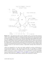
The report presents the figure shown herein as Figure
4.4.1 as a guide for spacing structural expansion joints in
beam and column frame buildings based on design temper-
ature change. The report includes data for numerous cities.
The report gives modifying factors that are applied to the
allowable building length as appropriate.
The report indicates that the curve is directly applicable
to buildings of beam-and-column construction, hinged at
the base, and with heated interiors. When other conditions
prevail, the following rules are applicable:
1. If the building will be heated only and will have
hinged-column bases, use the allowable length as
specified.
2. If the building will be air conditioned as well as
heated, increase the allowable length 15 percent (if the
environmental control system will run continuously).
3. If the building will be unheated, decrease the allow-
able length 33 percent.
4. If the building will have fixed column bases, decrease
the allowable length 15 percent.
5. If the building will have substantially greater stiffness
against lateral displacement in one direction decrease
the allowable length 25 percent.
When more than one of these design conditions prevails
in a building, the percentile factor to be applied should be
the algebraic sum of the adjustment factors of all the vari-
ous applicable conditions.
Regarding the type of structural expansion joint, most
engineers agree that the best method is to use a line of dou-
ble columns to provide a complete separation at the joints.
When joints other than the double column type are
employed, low friction sliding elements, such as shown in
Figure 4.4.2, are generally used. Slip connections may
6 / DESIGN GUIDE 7 / INDUSTRIAL BUILDINGS—ROOFS TO ANCHOR RODS, 2ND EDITION
Fig. 4.4.1 Expansion Joint Spacing Graph
[T k f F C C T h R t N 65
Fig. 4.4.1 Expansion Joint Spacing Graph
(Taken from F.C.C. Tech. Report No. 65, Expansion Joints in Buildings)
Fig. 4.4.2 Beam Expansion Joint
DESIGN GUIDE 7 / INDUSTRIAL BUILDINGS—ROOFS TO ANCHOR RODS, 2ND EDITION /7
induce some level of inherent restraint to movement due to
binding or debris build-up.
Very often buildings may be required to have firewalls in
specific locations. Firewalls may be required to extend
above the roof or they may be allowed to terminate at the
underside of the roof. Such firewalls become locations for
expansion joints. In such cases the detailing of joints can be
difficult.
Figures 4.4.2 through 4.4.5 depict typical details to per-
mit limited expansion. Additional details are given in archi-
tectural texts.
Expansion joints in the structure should always be car-
ried through the roofing. Additionally, depending on mem-
brane type, other joints called area dividers are necessary in
the roof membrane. These joints are membrane relief joints
only and do not penetrate the roof deck. Area divider joints
are generally placed at intervals of 150 ft to 250 ft for
adhered membranes, at somewhat greater intervals for bal-
lasted membranes, and 100 ft to 200 ft in the case of steel
roofs. Spacing of joints should be verified with manufac-
turer’s requirements. The range of movement between
joints is limited by the flexibility and movement potential of
the anchorage scheme and, in the case of standing seam
roofs, the clip design. Manufacturers’ recommendations
should be consulted and followed. Area dividers can also
be used to divide complex roofs into simple squares and
rectangles.
4.5 Roof Pitch, Drainage and Ponding
Prior to determining a framing scheme and the direction of
primary and secondary framing members, it is important to
decide how roof drainage is to be accomplished. If the
structure is heated, interior roof drains may be justified. For
unheated spaces exterior drains and gutters may provide the
solution.
For some building sites it may not be necessary to have
gutters and downspouts to control storm water, but their use
is generally recommended or required by the owner. Sig-
nificant operational and hazardous problems can occur
where water is discharged at the eaves or scuppers in cold
climates, causing icing of ground surfaces and hanging of
ice from the roof edge. This is a special problem at over-
head door locations and may occur with or without gutters.
Protection from falling ice must be provided at all building
service entries.
Performance of roofs with positive drainage is generally
good. Due to problems (for example, ponding, roofing dete-
rioration, leaking) that result from poor drainage, the Inter-
national Building Code, (ICC, 2003) requires a roof slope
of at least ¼ in. per ft.
Fig. 4.4.3 Joist Expansion Joint
Fig. 4.4.4 Joist Expansion Joint
Ponding, which is often not understood or is overlooked,
is a phenomenon that may lead to severe distress or partial
or general collapse.
Ponding as it applies to roof design has two meanings.
To the roofing industry, ponding describes the condition in
which water accumulated in low spots has not dissipated
within 24 hours of the last rainstorm. Ponding of this nature
is addressed in roof design by positive roof drainage and
control of the deflections of roof framing members. Pond-
ing, as an issue in structural engineering, is a load/deflec-
tion situation, in which, there is incremental accumulation
of rainwater in the deflecting structure. The purpose of a
ponding check is to ensure that equilibrium is reached
between the incremental loading and the incremental
deflection. This convergence must occur at a level of stress
that is within the allowable value.
The AISC specifications for both LRFD (AISC, 1999)
and ASD (AISC, 1989) give procedures for addressing the
problem of ponding where roof slopes and drains may be
inadequate. The direct method is expressed in Eq. K2-1 and
K2-2 of the specifications. These relations control the stiff-
ness of the framing members (primary and secondary) and
deck. This method, however, can produce unnecessarily
conservative results. A more exact method is provided in
Appendix K of the LRFD Specification and in Chapter K in
the Commentary in the ASD Specification.
The key to the use of the allowable stress method is the
calculation of stress in the framing members due to loads
present at the initiation of ponding. The difference between
0.8 F
y
and the initial stress is used to establish the required
stiffness of the roof framing members. The initial stress
(“at the initiation of ponding”) is determined from the loads
present at that time. These should include all or most of the
dead load and may include some portion of snow/rain/live
load. Technical Digest No. 3 published by the Steel Joist
Institute SJI (1971) gives some guidance as to the amount
of snow load that could be used in ponding calculations.
The amount of accumulated water used is also subject to
judgment. The AISC ponding criteria only applies to roofs
which lack “sufficient slope towards parts of free drainage
or adequate individual drains to prevent the accumulation
of rain water ” However, the possibility of plugged drains
means that the load at the initiation of ponding could
include the depth of impounded water at the level of over-
flow into adjacent bays, or the elevation of overflow drains
or, over the lip of roof edges or through scuppers. It is clear
from reading the AISC Specification and Commentary that
it is not necessary to include the weight of water that would
accumulate after the “initiation of ponding.” Where snow
load is used by the code, the designer may add 5 psf to the
roof load to account for the effect of rain on snow. Also,
consideration must be given to areas of drifted snow.
It is clear that judgment must be used in the determina-
tion of loading “at the initiation of ponding.” It is equally
clear that one hundred percent of the roof design load would
rarely be appropriate for the loading “at the initiation of
ponding.”
A continuously framed or cantilever system may be more
critical than a simple span system. With continuous fram-
ing, rotations at points of support, due to roof loads that are
not uniformly distributed, will initiate upward and down-
ward deflections in alternate spans. The water in the
uplifted bays drains into the adjacent downward deflected
bays, compounding the effect and causing the downward
deflected bays to approach the deflected shape of simple
spans. For these systems one approach to ponding analysis
8 / DESIGN GUIDE 7 / INDUSTRIAL BUILDINGS—ROOFS TO ANCHOR RODS, 2ND EDITION
Fig. 4.4.5 Truss Expansion Joint
could be based on simple beam stiffness, although a more
refined analysis could be used.
The designer should also consult with the plumbing
designer to establish whether or not a controlled flow (water
retention) drain scheme is being used. Such an approach
allows the selection of smaller pipes because the water is
impounded on the roof and slowly drained away. This
intentional impoundment does not meet the AISC criterion
of “drains to prevent the accumulation of rainwater ” and
requires a ponding analysis.
A situation that is not addressed by building code
drainage design is shown in Figure 4.5.1. The author has
investigated several roof ponding collapses where the accu-
mulation of water is greater than would be predicted by
drainage analysis for the area shown in Figure 4.5.1. As the
water drains towards the eave it finds the least resistance to
flow along the parapet to the aperture of the roof. Design-
ers are encouraged to pay close attention these situations,
and to provide a conservative design for ponding in the
aperture area.
Besides rainwater accumulation, the designer should give
consideration to excessive build-up of material on roof sur-
faces (fly ash, and other air borne material) from industrial
operations. Enclosed valleys, parallel high- and low-aisle
roofs and normal wind flows can cause unexpected build-
ups and possibly roof overload.
4.6 Joists and Purlins
A decision must be made whether to span the long direction
of bays with the main beams, trusses, or joist girders which
support short span joists or purlins, or to span the short
direction of bays with main framing members which sup-
port longer span joists or purlins. Experience in this regard
is that spanning the shorter bay dimension with primary
members will provide the most economical system. How-
ever, this decision may not be based solely on economics
but rather on such factors as ease of erection, future expan-
sion, direction of crane runs, location of overhead doors,
etc.
On the use of steel joists or purlins, experience again
shows that each case must be studied. Standard steel joist
specifications (SJI, 2002) are based upon distributed loads
only. Modifications for concentrated loads should be done
in accordance with the SJI Code Of Standard Practice. Hot-
rolled framing members should support significant concen-
trated loads. However, in the absence of large concentrated
loads, joist framing can generally be more economical than
hot rolled framing.
Cold-formed C and Z purlin shapes provide another
alternative to rolled W sections. The provisions contained
in the American Iron and Steel Institute’s Specification for
the Design of Cold-Formed Steel Structural Members
(AISI, 2001) should be used for the design of cold-formed
purlins. Additional economy can be achieved with C and Z
sections because they can be designed and constructed as
continuous members. However, progressive failure should
be considered if there is a possibility for a loss in continu-
ity after installation.
Other aspects of the use of C and Z sections include:
1. Z sections ship economically due to the fact that they
can be “nested.”
2. Z sections can be loaded through the shear center; C
sections cannot.
3. On roofs with appropriate slope a Z section will have
one principal axis vertical, while a C section provides
this condition only for flat roofs.
4. Many erectors indicate that lap bolted connections for
C or Z sections (bolted) are more expensive than the
simple welded down connections for joist ends.
5. At approximately a 30-ft span length C and Z sections
may cost about the same as a joist for the same load
per foot. For shorter spans C and Z sections are nor-
mally less expensive than joists.
5. ROOF TRUSSES
Primary roof framing for conventionally designed industrial
buildings generally consists of wide flange beams, steel
joist girders, or fabricated trusses. For relatively short spans
of 30- to 40-ft steel beams provide an economical solution,
particularly if a multitude of hanging loads are present. For
spans greater than 40 ft but less than 80-ft steel joist girders
are often used to support roof loads. Fabricated steel roof
trusses are often used for spans greater than 80 ft. In recent
years little has been written about the design of steel roof
trusses. Most textbooks addressing the design of trusses
were written when riveted connections were used. Today
welded trusses and field bolted trusses are used exclusively.
DESIGN GUIDE 7 / INDUSTRIAL BUILDINGS—ROOFS TO ANCHOR RODS, 2ND EDITION /9
Slope
Typical
Drain
Water
Flow
Parapet
Fig. 4.5.1 Aperture Drainage
Presented in the following paragraphs are concepts and
principles that apply to the design of roof trusses.
5.1 General Design and Economic Considerations
No absolute statements can be made about what truss con-
figuration will provide the most economical solution. For a
particular situation, however, the following statements can
be made regarding truss design:
1. Span-to-depth ratios of 15 to 20 generally prove to be
economical; however, shipping depth limitations
should be considered so that shop fabrication can be
maximized. The maximum depth for shipping is con-
servatively 14 ft. Greater depths will require the web
members to be field bolted, which will increase erec-
tion costs.
2. The length between splice points is also limited by
shipping lengths. The maximum shippable length
varies according to the destination of the trusses, but
lengths of 80 ft are generally shippable and 100 ft is
often possible. Because maximum available mill
length is approximately 70 ft, the distance between
splice points is normally set at a maximum of 70 ft.
Greater distances between splice points will generally
require truss chords to be shop spliced.
3. In general, the rule “deeper is cheaper” is true; how-
ever, the costs of additional lateral bracing for more
flexible truss chords must be carefully examined rela-
tive to the cost of larger chords which may require less
lateral bracing. The lateral bracing requirements for
the top and bottom chords should be considered inter-
actively while selecting chord sizes and types. Partic-
ular attention should be paid to loads that produce
compression in the bottom chord. In this condition
additional chord bracing will most likely be necessary.
4. If possible, select truss depths so that tees can be used
for the chords rather than wide flange shapes. Tees
can eliminate (or reduce) the need for gusset plates.
5. Higher strength steels (F
y
= 50 ksi or more) usually
results in more efficient truss members.
6. Illustrated in Figures 5.1.1 and 5.1.2 are web arrange-
ments that generally provide economical web systems.
7. Utilize only a few web angle sizes, and make use of
efficient long leg angles for greater resistance to buck-
ling. Differences in angle sizes should be recogniza-
ble. For instance avoid using an angle 4×3×¼ and an
angle 4×3×
5
/16 in the same truss.
8. HSS, wide flange or pipe sections may prove to be
more effective web members at some web locations,
especially where subsystems are to be supported by
web members.
9. Designs using the AISC LRFD Specification (AISC,
1999) will often lead to truss savings when heavy long
span trusses are required. This is due to the higher DL
to LL ratios for these trusses.
10. The weight of gusset plates, shim plates and bolts can
be significant in large trusses. This weight must be
considered in the design since it often approaches 10
to 15 percent of the truss weight.
11. If trusses are analyzed using frame analysis computer
programs and rigid joints are assumed, secondary
10 / DESIGN GUIDE 7 / INDUSTRIAL BUILDINGS—ROOFS TO ANCHOR RODS, 2ND EDITION
Fig. 5.1.1 Economical Truss Web Arrangement
Fig. 5.1.2 Economical Truss Web Arrangement
bending moments will show up in the analysis. The
reader is referred to (Nair, 1988a) wherein it is sug-
gested that so long as these secondary stresses do not
exceed 4,000 psi they may be neglected. Secondary
stresses should not be neglected if the beneficial
effects of continuity are being considered in the design
process, for example, effective length determination.
The designer must be consistent. That is, if the joints
are considered as pins for the determination of forces,
then they should also be considered as pins in the
design process. The assumption of rigid joints in some
cases may provide unconservative estimates on the
deflection of the truss.
12. Repetition is beneficial and economical. Use as few
different truss depths as possible. It is cheaper to vary
the chord size as compared to the truss depth.
13. Wide flange chords with gussets may be necessary
when significant bending moments exist in the chords
(i.e. subsystems not supported at webs or large dis-
tances between webs).
14. The AISC Manual of Steel Construction can provide
some additional guidance on truss design and detailing.
15. Design and detailing of long span joists and joist gird-
ers shall be in accordance with SJI specifications (SJI,
2002).
5.2 Connection Considerations
1. As mentioned above, tee chords are generally eco-
nomical since they can eliminate gusset plates. The
designer should examine the connection requirements
to determine if the tee stem is in fact long enough to
eliminate gusset requirements. The use of a deeper tee
stem is generally more economical than adding
numerous gusset plates even if this means an addition
in overall weight.
2. Block shear requirements and the effective area in
compression should be carefully checked in tee stems
and gussets (AISC, Appendix B). Shear rupture of
chord members at panel points should also be investi-
gated since this can often control wide flange chords.
3. Intermediate connectors (stitch fasteners or fillers)
may be required for double web members. Examples
of intermediate connector evaluation can be found in
the AISC Manual.
4. If wide flange chords are used with wide flange web
members it is generally more economical to orient the
chords with their webs horizontal. Gusset plates for
the web members can then be either bolted or welded
to the chord flanges. To eliminate the cost of fabricat-
ing large shim or filler plates for the diagonals, the use
of comparable depth wide flange diagonals should be
considered.
5. When trusses require field bolted joints the use of slip-
critical bolts in conjunction with oversize holes will
allow for erection alignment. Also if standard holes
are used with slip-critical bolts and field “fit-up” prob-
lems occur, holes can be reamed without significantly
reducing the allowable bolt shears.
6. For the end connection of trusses, top chord seat type
connections should also be considered. Seat connec-
tions allow more flexibility in correcting column-truss
alignment during erection. Seats also provide for effi-
cient erection and are more stable during erection than
“bottom bearing” trusses. When seats are used, a sim-
ple bottom chord connection is recommended to pre-
vent the truss from rolling during erection.
7. For symmetrical trusses use a center splice to simplify
fabrication even though forces may be larger than for
an offset splice.
8. End plates can provide efficient compression splices.
9. It is often less expensive to locate the work point of
the end diagonal at the face of the supporting member
rather than designing the connection for the eccentric-
ity between the column centerline and the face of the
column.
5.3 Truss Bracing
Stability bracing is required at discrete locations where the
designer assumes braced points or where braced points are
required in the design of the members in the truss. These
locations are generally at panel points of the trusses and at
the ends of the web members. To function properly the
braces must have sufficient strength and stiffness. Using
standard bracing theory, the brace stiffness required (Factor
of Safety = 2.0) is equal to 4P/L, where P equals the force
to be braced and L equals the unbraced length of the col-
umn. The required brace force equals 0.004P. As a general
rule the stiffness requirement will control the design of the
bracing unless the bracing stiffness is derived from axial
stresses only. Braces that displace due to axial loads only
are very stiff, and thus the strength requirement will control.
It should be noted that the AISE Technical Report No. 13
requires a 0.025P force requirement for bracing. More
refined bracing equations are contained in a paper by Lutz
DESIGN GUIDE 7 / INDUSTRIAL BUILDINGS—ROOFS TO ANCHOR RODS, 2ND EDITION /11
and Fisher titled, A Unified Approach for Stability Bracing
Requirements (Lutz, 1985). Requirements for truss bottom
chord bracing are discussed in a paper by Fisher titled, The
Importance of Tension Chord Bracing (Fisher, 1983).
These requirements do not necessarily apply to long span
joists or joist girders.
Designers are often concerned about the number of “out-
of-straight” trusses that should be considered for a given
bracing situation. No definitive rules exist; however, the
Australian Code indicates that no more than seven out of
straight members need to be considered. Chen and Tong
(1994) recommend that columns be considered in the
out-of-straight condition where n = the total number of
columns in a story. This equation suggests that trusses
could be considered in the bracing design. Thus, if ten
trusses were to be braced, bracing forces could be based on
four trusses.
Common practice is to provide horizontal bracing every
five to six bays to transfer bracing forces to the main force
resisting system. In this case the brace forces should be cal-
culated based on the number of trusses between horizontal
bracing.
A convenient approach to the stability bracing of truss
compression chords is discussed in a paper by entitled
“Simple Solutions to Stability Problems in the Design
Office” (Nair, 1988b). The solution presented is based
upon the brace stiffness requirements controlled by an X-
braced system. The paper indicates that as long as the hor-
12 / DESIGN GUIDE 7 / INDUSTRIAL BUILDINGS—ROOFS TO ANCHOR RODS, 2ND EDITION
Strut
Truss Chord
Diagonal
Bracing
θ
= 22.5° to 67.5°
θ
Fig. 5.3.1 Horizontal X-Bracing Arrangement
Design Forces
(Kips)
Horizontal Truss Web Member Forces
Member
Panel Shear
Force = (1.414)(Panel Shear)
C1-D2
D1-C2
0.006(6X600) = 21.6
30.5
C2-D3
D2-C3
0.006(6X800) = 28.8
40.7
C3-D4
D3-C4
0.006(6X1000) = 36.0
50.9
Horizontal Truss Chord Forces
Member
Member Forces
C1-C2
D1-D2
21.6
C2-C3
D2-D3
21.6 + 28.8 = 50.4
C3-C4
D3-D4
50.4 + 36 = 86.4
Strut Forces
Member
Force = (1.2%)(Ave. Chord Force)
A4-B4, E4-F4
12.0
B4-C4, D4-E4
24.0
C4-D4
36.0
A3-B3, E3-F3
10.8
B3-C3, D3-E3
21.6
C3-D3
32.4
A2-B2, E2-F2
B2-C2, D2-E2
C2-D2
8.4
16.8
25.2
A1-B1, E1-F1
B1-C1, D1-E1
C1-D1
3.6
7.2
10.8
Note: Forces not shown are symmetrical
n
n
izontal X-bracing system comprises axially loaded mem-
bers arranged as shown in Figure 5.3.1, the bracing can be
designed for 0.6 percent of the truss chord axial load. Since
two truss chord sections are being braced at each bracing
strut location the strut connections to the trusses must be
designed for 1.2 percent of the average chord axial load for
the two adjacent chords. In the reference it is pointed out
that the bracing forces do not accumulate along the length
of the truss; however, the brace force requirements do accu-
mulate based on the number of trusses considered braced by
the bracing system.
In addition to stability bracing, top and bottom chord
bracing may also be required to transfer wind or seismic lat-
eral loads to the main lateral stability system. The force
requirements for the lateral loads must be added to the sta-
bility force requirements. Lateral load bracing is placed in
either the plane of the top chord or the plane of the bottom
chord, but generally not in both planes. Stability require-
ments for the unbraced plane can be transferred to the later-
ally braced plane by using vertical sway braces.
EXAMPLE 5.3.1
Roof Truss Stability Bracing
For the truss system shown in Figure 5.3.2 determine the
brace forces in the horizontal bracing system. Use the pro-
cedure discussed by (Nair, 1988b).
Solution:
Because the diagonal bracing layout as shown in Figure
5.3.2 forms an angle of 45 degrees with the trusses, the
solution used in the paper by Nair, (1988b) is suitable. The
bracing force thus equals 0.6 percent of the chord axial
load. Member forces are summarized above.
5.4 Erection Bracing
The engineer of record is not responsible for the design of
erection bracing unless specific contract arrangements
incorporate this responsibility into the work. However,
designers must be familiar with OSHA erection require-
ments (OSHA, 2001) relative to their designs.
Even though the designer of trusses is not responsible for
the erection bracing, the designer should consider sequence
and bracing requirements in the design of large trusses in
order to provide the most cost effective system. Large
trusses require significant erection bracing not only to resist
wind and construction loads but also to provide stability
until all of the gravity load bracing is installed. Significant
cost savings can be achieved if the required erection brac-
ing is incorporated into the permanent bracing system.
Erection is generally accomplished by first connecting
two trusses together with strut braces and any additional
erection braces to form a stable box system. Additional
trusses are held in place by the crane or cranes until they
can be “tied off” with strut braces to the already erected sta-
ble system. Providing the necessary components to facili-
tate this type of erection sequence is essential for a cost
effective project.
Additional considerations are as follows:
1. Columns are usually erected first with the lateral brac-
ing system (see Figure 5.4.1). If top chord seats are
DESIGN GUIDE 7 / INDUSTRIAL BUILDINGS—ROOFS TO ANCHOR RODS, 2ND EDITION /13
Fig. 5.3.2 Horizontal Bracing Systen
Fig. 5.4.1 Wall Bracing Erection Sequence
123 4 5 6 7
A
B
C
D
E
F
Horizontal
Truss
Framing Plan
(600k) (800k) (1000k)
Truss Elevation
Truss
Chord
Web
Diagonals
Bracing
Struts
45°
Top Chord Seats Bottom Bearing
Bracing
installed
prior to
truss
erection.
Column
Column
Bearing
Seats
Bracing installed
while crane holds
trusses.
used, the trusses can be quickly positioned on top of
the columns, braced to one another.
Bottom chord bearing trusses require that additional
stability bracing be installed at ends of trusses while
the cranes hold the trusses in place. This can slow
down the erection sequence.
2. Since many industrial buildings require clear spans,
systems are often designed as rigid frames. By design-
ing rigid frames, erection is facilitated, in that, the
sidewall columns are stabilized in the plane of the
trusses once the trusses are adequately anchored to the
columns. This scheme may require larger columns
than a braced frame system; however, savings in brac-
ing and erection time can often offset these costs.
3. Wide flange beams, HSS or pipe sections should be
used to laterally brace large trusses at key locations
during erection because of greater stiffness. Steel
joists can be used; however, two notes of caution are
advised:
a. Erection bracing strut forces must be provided to
the joist manufacturer; and it must be made clear
whether joist bridging and roof deck will be in
place when the erection forces are present. Large
angle top chords in joists may be required to con-
trol the joist slenderness ratio so that it does not
buckle while serving as the erection strut.
b. Joists are often not fabricated to exact lengths and
long slotted holes are generally provided in joist
seats. Slotted holes for bolted bracing members
should be avoided because of possible slippage.
Special coordination with the joist manufacturer is
required to eliminate the slots and to provide a suit-
able joist for bracing. In addition the joists must be
at the job site when the erector wishes to erect the
trusses.
4. Wind forces on the trusses during erection can be con-
siderable. See Design Loads on Structures During
Construction, ASCE 37-02, ASCE (2002), for detailed
treatment of wind forces on buildings during construc-
tion. The AISC Code of Standard Practice states that
“These temporary supports shall be sufficient to
secure the bare Structural Steel framing or any portion
thereof against loads that are likely to be encountered
during erection, including those due to wind and those
that result from erection operations.” The projected
area of all of the truss and other roof framing members
can be significant, and in some cases the wind forces
on the unsided structure are actually larger than those
after the structure is enclosed.
5. A sway frame is normally required in order to plumb
the trusses during erection. These sway frames should
normally occur every fourth or fifth bay. An elevation
view of such a truss is shown in Figure 5.4.2. These
frames can be incorporated into the bottom chord
bracing system. Sway frames are also often used to
transfer forces from one chord level to another as dis-
cussed earlier. In these cases the sway frames must not
only be designed for stability forces, but also the
required load transfer forces.
5.5 Other Considerations
1. Camber large clear span trusses to accommodate dead
load deflections. The fabricator accomplishes this by
either adjusting the length of the web members in the
truss and keeping the top chord segments straight or
by curving the top chord. Tees can generally be easily
curved during assembly whereas wide flange sections
may require cambering prior to assembly. If signifi-
cant top chord pitch is provided and if the bottom
chord is pitched, camber may not be required. The
engineer of record is responsible for providing the fab-
ricator with the anticipated dead load deflection and
special cambering requirements.
The designer must carefully consider the truss deflec-
tion and camber adjacent to walls, or other portions of
the structure where stiffness changes cause variations
in deflections. This is particularly true at building
endwalls, where differential deflections may damage
continuous purlins or connections.
2. Connection details that can accommodate temperature
changes are generally necessary. Long span trusses
that are fabricated at one temperature and erected at a
significantly different temperature can grow or shrink
significantly.
14 / DESIGN GUIDE 7 / INDUSTRIAL BUILDINGS—ROOFS TO ANCHOR RODS, 2ND EDITION
Purlin
Bottom Chord Bracing
C Truss
L
C Truss
L
Sway Brace
Fig. 5.4.2 Sway Frame
3. Roof deck diaphragm strength and stiffness are com-
monly used for strength and stability bracing for joists.
The diaphragm capabilities must be carefully evalu-
ated if it is to be used for bracing of large clear span
trusses.
For a more comprehensive treatment of erection bracing
design, read Serviceability Design Considerations for Steel
Buildings, (Fisher and West, 2003).
6. WALL SYSTEMS
The wall system can be chosen for a variety of reasons and
the cost of the wall can vary by as much as a factor of three.
Wall systems include:
1. Field assembled metal panels.
2. Factory assembled metal panels.
3. Precast concrete panels.
4. Masonry walls (part or full height).
A particular wall system may be selected over others for
one or more specific reasons including:
1. Cost.
2. Appearance.
3. Ease of erection.
4. Speed of erection.
5. Insulating properties.
6. Fire considerations.
7. Acoustical considerations.
8. Ease of maintenance/cleaning.
9. Ease of future expansion.
10. Durability of finish.
11. Maintenance considerations.
Some of these factors will be discussed in the following
sections on specific systems. Other factors are not discussed
and require evaluation on a case-by-case basis.
6.1 Field-Assembled Panels
Field assembled panels consist of an outer skin element,
insulation, and in some cases an inner liner panel. The pan-
els vary in material thickness and are normally galvanized,
galvanized prime painted suitable for field painting, or pre-
finished galvanized. Corrugated aluminum liners are also
used. When aluminum materials are used their compatibil-
ity with steel supports should be verified with the manufac-
turer since aluminum may cause corrosion of steel. When
an inner liner is used, some form of hat section interior sub-
girts are generally provided for stiffness. The insulation is
typically fiberglass or foam. If the inner liner sheet is used
as the vapor barrier all joints and edges should be sealed.
Specific advantages of field assembled wall panels
include:
1. Rapid erection of panels.
2. Good cost competition, with a large number of manu-
facturers and contractors being capable of erecting
panels.
3. Quick and easy panel replacement in the event of
panel damage.
4. Openings for doors and windows that can be created
quickly and easily.
5. Panels that are lightweight, so that heavy equipment is
not required for erection. Also large foundations and
heavy spandrels are not required.
DESIGN GUIDE 7 / INDUSTRIAL BUILDINGS—ROOFS TO ANCHOR RODS, 2ND EDITION /15
Fig. 6.1.1 Wall Thermal Break Detail
6. Acoustic surface treatment that can be added easily to
interior panel wall at reasonable cost.
A disadvantage of field assembled panels in high humid-
ity environments can be the formation of frost or condensa-
tion on the inner liner when insulation is placed only
between the subgirt lines. The metal-to-metal contact (out-
side sheet-subgirt-inside sheet) should be broken to reduce
thermal bridging. A detail that has been used successfully
is shown in Figure 6.1.1. Another option may be to provide
rigid insulation between the girt and liner on one side. In
any event, the wall should be evaluated for thermal trans-
mittance in accordance with (ASHRAE, 1989).
6.2 Factory-Assembled Panels
Factory assembled panels generally consist of interior liner
panels, exterior metal panels and insulation. Panels provid-
ing various insulating values are available from several
manufacturers. These systems are generally proprietary
and must be designed according to manufacturer’s recom-
mendations.
The particular advantages of these factory-assembled
panels are:
1. Panels are lightweight and require no heavy cranes for
erection, no large foundations or heavy spandrels.
2. Panels can have a hard surface interior liner.
3. Panel side lap fasteners are normally concealed pro-
ducing a “clean” appearance.
4. Documented panel performance characteristics deter-
mined by test or experience may be available from
manufacturers.
Disadvantages of factory-assembled panels include:
1. Once a choice of panel has been made, future expan-
sions may effectively require use of the same panel to
match color and profile, thus competition is essentially
eliminated.
2. Erection procedures usually require starting in one
corner of a structure and proceeding to the next corner.
Due to the interlocking nature of the panels it may be
difficult to add openings in the wall.
3. Close attention to coordination of details and toler-
ances with collateral materials is required.
4. Thermal changes in panel shape may be more apparent.
6.3 Precast Wall Panels
Precast wall panels for industrial buildings could utilize one
or more of a variety of panel types including:
1. Hollow core slabs.
2. Double-T sections.
3. Site cast tilt-up panels.
4. Factory cast panels.
Panels can be either load bearing or nonload bearing and
can be obtained in a wide variety of finishes, textures and
colors. Also, panels may be of sandwich construction and
contain rigid insulation between two layers of concrete.
Such insulated panels can be composite or noncomposite.
Composite panels normally have a positive concrete con-
nection between inner and outer concrete layers. These
panels are structurally stiff and are good from an erection
point of view but the “positive” connection between inner
and outer layers may lead to exterior surface cracking when
the panels are subjected to a temperature differential. The
direct connection can also provide a path for thermal bridg-
ing.
True sandwich panels connect inner and outer concrete
layers with flexible metal ties. Insulation is exposed at all
panel edges. These panels are more difficult to handle and
erect, but normally perform well.
Precast panels have advantages for use in industrial
buildings:
1. A hard surface is provided inside and out.
2. These panels produce an architecturally “clean”
appearance.
3. Panels have inherent fire resistance characteristics.
4. Intermediate girts are usually not required.
5. Use of load bearing panels can eliminate exterior
framing and reduce cost.
6. Panels provide an excellent sound barrier.
Disadvantages of precast wall panel systems include:
1. Matching colors of panels in future expansion may be
difficult.
2. Composite sandwich panels have “cold spots” with
potential condensation problems at panel edges.
3. Adding wall openings can be difficult.
4. Panels have poor sound absorption characteristics.
16 / DESIGN GUIDE 7 / INDUSTRIAL BUILDINGS—ROOFS TO ANCHOR RODS, 2ND EDITION
5. Foundations and grade beams may be heavier than for
other panel systems.
6. Heavier eave struts are required for steel frame struc-
tures than for other systems.
7. Heavy cranes are required for panel erection.
8. If panels are used as load bearing elements, expansion
in the future could present problems.
9. Close attention to tolerances and details to coordinate
divergent trades are required.
10. Added dead weight of walls can affect seismic design.
6.4 Masonry Walls
Use of masonry walls in industrial buildings is common.
Walls can be load bearing or non-load bearing.
Some advantages of the use of masonry construction are:
1. A hard surface is provided inside and out.
2. Masonry walls have inherent fire resistance character-
istics.
3. Intermediate girts are usually not required.
4. Use of load bearing walls can eliminate exterior fram-
ing and reduce cost.
5. Masonry walls can serve as shear walls to brace
columns and resist lateral loads.
6. Walls produce a flat finish, resulting in an ease of both
maintenance and dust control considerations.
Disadvantages of masonry include:
1. Masonry has comparatively low material bending
resistance. Walls are normally adequate to resist nor-
mal wind loads, but interior impact loads can cause
damage.
2. Foundations may be heavier than for metal wall panel
construction.
3. Special consideration is required in the use of masonry
ties, depending on whether the masonry is erected
before or after the steel frame.
4. Buildings in seismic regions may require special rein-
forcing and added dead weight may increase seismic
forces.
6.5 Girts
Typical girts for industrial buildings are hot rolled channel
sections or cold-formed light gage C or Z sections. In some
instances HSS are used to eliminate the need for compres-
sion flange bracing. In recent years, cold-formed sections
have gained popularity because of their low cost. As men-
tioned earlier, cold-formed Z sections can be easily lapped
to achieve continuity resulting in further weight savings and
reduced deflections, Z sections also ship economically.
Additional advantages of cold-formed sections compared
with rolled girt shapes are:
1. Metal wall panels can be attached to cold-formed girts
quickly and inexpensively using self-drilling fasteners.
2. The use of sag rods is often not required.
Hot-rolled girts are often used when:
1. Corrosive environments dictate the use of thicker sec-
tions.
2. Common cold-formed sections do not have sufficient
strength for a given span or load condition.
3. Girts will receive substantial abuse from operations.
4. Designers are unfamiliar with the availability and
properties of cold-formed sections.
Both hot-rolled and cold-formed girts subjected to pres-
sure loads are normally considered laterally braced by the
wall sheathing. Negative moment regions in continuous
cold-formed girt systems are typically considered laterally
braced at inflection points and at girt to column connec-
tions. Continuous systems have been analyzed by assum-
ing:
1. A single prismatic section throughout.
2. A double moment of inertia condition within the
lapped section of the cold-formed girt.
Research indicates that an analytical model assuming a
single prismatic section is closer to experimentally deter-
mined behavior (Robertson, 1986).
The use of sag rods is generally required to maintain hor-
izontal alignment of hot-rolled sections. The sag rods are
often assumed to provide lateral restraint against buckling
for suction loads. When used as bracing, the sag rods must
be designed to take tension in either the upward or down-
ward direction. The paneling is assumed to provide lateral
support for pressure loads. Lateral stability for the girt
based on this assumption is checked using Chapter F of the
AISC Specification.
The typical design procedure for hot-rolled girts is as fol-
lows:
DESIGN GUIDE 7 / INDUSTRIAL BUILDINGS—ROOFS TO ANCHOR RODS, 2ND EDITION /17
1. Select the girt size based on pressure loads, assuming
full flange lateral support.
2. Check the selected girt for sag rod requirements based
on deflections and bending stresses about the weak
axis of the girt.
3. Check the girt for suction loads using Chapter F of the
AISC Specification.
4. If the girt is inadequate, increase its size or add sag
rods.
5. Check the girt for serviceability requirements.
6. Check the sag rods for their ability to resist the twist
of the girt due to the suction loads. The sag rod and
siding act to provide the torsional brace.
Cold-formed girts should be designed in accordance with
the provisions of the American Iron and Steel Institute
North American Specification for the Design of Cold-
Formed Steel Structural Members (AISI, 2001). Many
manufacturers of cold-formed girts provide design assis-
tance, and offer load span tables to aid design.
Section C3.1.2 “Lateral Buckling Strength” of the AISI
Specification provides a means for determining cold-
formed girt strength when the compression flange of the girt
is attached to sheeting (fully braced) or when discrete point
braces (sag rods) are used. For lapped systems, the sum of
the moment capacities of the two lapped girts is normally
assumed to resist the negative moment over the support.
For full continuity to exist, a lap length on each side of the
column support should be equal to at least 1.5 times the girt
depth (Robertson, 1986). Additional provisions are given
in Section C3 for strength considerations relative to shear,
web crippling, and combined bending and shear.
Section C3.1.3 “Beams with One Flange Attached to
Deck or Sheathing” provides a simple procedure to design
cold-formed girts subjected to suction loading. The basic
equation for the determination of the girt strength is:
M
n
= RS
e
F
y
The values of R are shown below:
S
e
= Elastic section modulus, of the effective section,
calculated with the extreme compression or tension
fiber at F
y
.
F
y
= Specified minimum yield stress.
Other restrictions relative to insulation, girt geometry,
wall panels, fastening systems between wall panels and
girts, etc. are discussed in the AISI specifications.
18 / DESIGN GUIDE 7 / INDUSTRIAL BUILDINGS—ROOFS TO ANCHOR RODS, 2ND EDITION
Simple Span C- or Z-Section R Values
Depth Range, in.
Profile
R
d ≤ 6.5
C or Z
0.70
6.5 < d ≤ 8.5
C or Z
0.65
8.5 < d ≤ 11.5
Z
0.50
8.5 < d ≤ 11.5
C
0.40
Fig. 6.6.1 Wind Column Reaction Load Transfer Fig. 6.6.2 Wind Column Reaction Load Transfer