mass concrete
Bạn đang xem bản rút gọn của tài liệu. Xem và tải ngay bản đầy đủ của tài liệu tại đây (744.34 KB, 42 trang )
ACI committee reports, guides, standard practices, design
handbooks, and commentaries are intended for guidance in
planning, designing, executing, and inspecting construction.
This document is intended for the use of individuals who are
competent to evaluate the significance and limitations of its
content and recommendations and who will accept responsi-
bility for the application of the material it contains. The
American Concrete Institute disclaims any and all responsi-
bility for the application of the stated principles. The Institute
shall not be liable for any loss or damage arising therefrom.
Reference to this document shall not be made in contract
documents. If items found in this document are desired by
the Architect/Engineer to be a part of the contract docu-
ments, they shall be restated in mandatory language for in-
corporation by the Architect/Engineer.
Synopsis
Mass concrete is “any volume of concrete with dimensions large enough to
require that measures be taken to cope with generation of heat from hydra-
tion of the cement and attendant volume change to minimize cracking.”
The design of mass concrete structures is generally based on durability,
economy, and thermal action, with strength often being a secondary con-
cern. Since the cement-water reaction is exothermic by nature, the temper-
ature rise within a large concrete mass, where the heat is not dissipated,
can be quite high. Significant tensile stresses may develop from the volume
change associated with the increase and decrease of temperature within
the mass. Measures should be taken where cracking due to thermal behav-
ior may cause loss of structural integrity and monolithic action, or may
Mass Concrete
Reported by ACI Committee 207
Gary R. Mass Woodrow L. Burgess*
Chairman Chairman, Task Group
Edward A. Abdun-Nur* Robert W. Cannon David Groner Walter H. Price*† Ernest K. Schrader*
Fred A. Anderson* Roy W. Carlson Kenneth D. Hansen Milos Polivka Roger L. Sprouse
Richard A. Bradshaw, Jr.* James L. Cope* Gordon M. Kidd Jerome M. Raphael* John H. Stout
Edward G. W. Bush James R. Graham* W. Douglas McEwen Patricia J. Roberts Carl R. Wilder
James E. Oliverson*
*Members of the task group who prepared this report.
†Deceased
Members of Committee 207 who voted on the 1996 revisions:
John M. Scanlon John R. Hess
Chairman Chairman, Task Group
Dan A. Bonikowsky James L. Cope Michael I. Hammons Meng K. Lee Ernest K. Schrader
Robert W. Cannon Luis H. Diaz Kenneth D. Hansen Gary R. Mass Glenn S. Tarbox
Ahmed F. Chraibi Timothy P. Dolen James K. Hinds Robert F. Oury Stephen B. Tatro
Allen J. Hulshizer
ACI 207.1R-96
cause excessive seepage and shortening of the service life of the structure,
or may be esthetically objectionable. Many of the principles in mass con-
crete practice can also be applied to general concrete work whereby certain
economic and other benefits may be realized.
This report contains a history of the development of mass concrete practice
and discussion of materials and concrete mix proportioning, properties,
construction methods and equipment, and thermal behavior. It covers tradi-
tionally placed and consolidated mass concrete, and does not cover roller-
compacted concrete. Mass concrete practices were largely developed from
concrete dam construction, where temperature-related cracking was first
identified. Temperature-related cracking has also been experienced in other
thick-section concrete structures, including mat foundations, pile caps,
bridge piers, thick walls, and tunnel linings.
Keywords: admixtures; aggregate gradation; aggregate size; aggregates; air
entrainment; arch dams; batching; bridge piers; cements; compressive
strength; concrete construction; concrete dams; cooling; cracking (fractur-
ing); creep; curing; diffusivity; durability; fly ash; formwork (construction);
gravity dams; heat generation; heat of hydration; history; instrumentation;
mass concrete; mix proportioning; mixing; modulus of elasticity; perme-
ability; placing; Poisson’s ratio; pozzolans; shear properties; shrinkage;
strains; stresses; temperature control; temperature rise (in concrete); ther-
mal expansion; thermal gradient; thermal properties; vibration; volume
change.
207.1R-1
ACI 207.1R-96 became effective November 21, 1996. This document replaces ACI
207.1R-87.
Copyright
1997, American Concrete Institute.
All rights reserved including rights of reproduction and use in any form or by any
means, including the making of copies by any photo process, or by electronic or
mechanical device, printed, written, or oral, or recording for sound or visual reproduc-
tion or for use in any knowledge or retrieval system or device, unless permission in
writing is obtained from the copyright proprietors.
207.1R-2 ACI COMMITTEE REPORT
CONTENTS
Chapter 1—Introduction and historical
developments, p. 207.1R-2
1.1—Scope
1.2—History
1.3—Temperature control
1.4—Long-term strength design
Chapter 2—Materials and mix proportioning, p.
207.1R-6
2.1—General
2.2—Cements
2.3—Pozzolans and ground slag
2.4—Chemical admixtures
2.5—Aggregates
2.6—Water
2.7—Selection of proportions
2.8—Temperature control
Chapter 3—Properties, p. 207.1R-13
3.1—General
3.2—Strength
3.3—Elastic properties
3.4—Creep
3.5—Volume change
3.6—Permeability
3.7—Thermal properties
3.8—Shear properties
3.9—Durability
Chapter 4—Construction, p. 207.1R-22
4.1—Batching
4.2—Mixing
4.3—Placing
4.4—Curing
4.5—Forms
4.6—Height of lifts and time intervals between lifts
4.7—Cooling and temperature control
4.8—Grouting contraction joints
Chapter 5—Behavior, p. 207.1R-29
5.1—Thermal stresses and cracking
5.2—Volume change
5.3—Heat generation
5.4—Heat dissipation studies
5.5—Instrumentation
Chapter 6—References, p. 207.1R-38
6.1—Specified and recommended references
6.2—Cited references
6.3—Additional references
Appendix—Metric examples, p. 207.1R-40
CHAPTER 1—INTRODUCTION AND HISTORICAL
DEVELOPMENTS
1.1—Scope
1.1.1—“Mass concrete” is defined in ACI 116R as “any
volume of concrete with dimensions large enough to require
that measures be taken to cope with generation of heat from
hydration of the cement and attendant volume change to
minimize cracking.” The design of mass concrete structures
is generally based principally on durability, economy, and
thermal action, with strength often being a secondary rather
than a primary concern. The one characteristic that distin-
guishes mass concrete from other concrete work is thermal
behavior. Since the cement-water reaction is exothermic by
nature, the temperature rise within a large concrete mass,
where the heat is not quickly dissipated, can be quite high
(see 5.1.1). Significant tensile stresses and strains may de-
velop from the volume change associated with the increase
and decrease of temperature within the mass. Measures
should be taken where cracking due to thermal behavior may
cause loss of structural integrity and monolithic action, or
may cause excessive seepage and shortening of the service
life of the structure, or may be esthetically objectionable.
Many of the principles in mass concrete practice can also be
applied to general concrete work whereby certain economic
and other benefits may be realized.
This report contains a history of the development of mass
concrete practice and discussion of materials and concrete
mix proportioning, properties, construction methods and
equipment, and thermal behavior. This report covers tradi-
tionally placed and consolidated mass concrete, and does not
cover roller-compacted concrete. Roller-compacted concrete
is described in detail in ACI 207.5R.
Mass concreting practices were developed largely from
concrete dam construction, where temperature-related crack-
ing was first identified. Temperature-related cracking also
has been experienced in other thick-section concrete struc-
tures, including mat foundations, pile caps, bridge piers,
thick walls, and tunnel linings.
High compressive strengths are usually not required in
mass concrete structures; thin arch dams are exceptions.
Massive structures, such as gravity dams, resist loads by vir-
tue of their shape and mass, and only secondarily by their
strength. Of more importance are durability and properties
connected with temperature behavior and the tendency for
cracking.
The effects of heat generation, restraint, and volume
changes on the design and behavior of massive reinforced el-
ements and structures are discussed in ACI 207.2R. Cooling
and insulating systems for mass concrete are addressed in
ACI 207.4R. Mixture proportioning for mass concrete is dis-
cussed in ACI 211.1.
1.2—History
1.2.1—When concrete was first used in dams, the dams
were small and the concrete was mixed by hand. The port-
land cement usually had to be aged to comply with a “boil-
ing” soundness test, the aggregate was bank-run sand and
gravel, and proportioning was by the shovelful (Davis
207.1R-3MASS CONCRETE
1963).
*
Tremendous progress has been made since the early
days, and the art and science of dam building practiced today
has reached a highly advanced state. The selection and pro-
portioning of concrete materials to produce suitable strength,
durability, and impermeability of the finished product can be
predicted and controlled with accuracy.
1.2.2—Covered herein are the principal steps from those
very small beginnings to the present. In large dam construc-
tion there is now exact and automatic proportioning and mix-
ing of materials. Concrete in 12-yd
3
(9-m
3
) buckets can be
placed by conventional methods at the rate of 10,000 yd
3
/day
(7650 m
3
/day) at a temperature of less than 50 F (10 C) as
placed, even during the hottest weather. Grand Coulee Dam
still holds the all-time record monthly placing rate of
536,250 yd
3
(410,020 m
3
) followed by the more recent
achievement at Itaipu Dam on the Brazil-Paraguay border of
440,550 yd
3
(336,840 m
3
) (Itaipu Binacional 1981). Lean
mixes are now made workable by means of air-entraining
and other chemical admixtures and the use of finely divided
pozzolanic materials. Water-reducing, strength-enhancing,
and set-controlling chemical admixtures are effective in re-
ducing the required cement content to a minimum as well as
in controlling the time of setting. With the increased atten-
tion to roller-compacted concrete, a new dimension has been
given to mass concrete construction. The record monthly
placing rate of 328,500 yd
3
(250,200 m
3
) for roller-compact-
ed concrete was achieved at Tarbela Dam in Pakistan. Plac-
ing rates for no-slump concrete, using large earth-moving
equipment for transportation and large vibrating rollers for
consolidation, appear to be limited only by the size of the
project and its plant's ability to produce concrete. Those con-
cerned with concrete dam construction should not feel that
the ultimate has been reached, but they are justified in feeling
some satisfaction with the progress that has been made.
1.2.3 Prior to 1900—Prior to the beginning of the twenti-
eth century, much of the portland cement used in the United
States was imported from Europe. All cements were very
coarse by present standards—and quite commonly they were
underburned and had a high free lime content. For dams of
that period, bank-run sand and gravel were used without ben-
efit of washing to remove objectionable dirt and fines. Con-
crete mixes varied widely in cement content and in sand/
coarse aggregate ratio. Mixing was usually by hand and pro-
portioning by shovel, wheelbarrow, box, or cart. The effect
of water-cement ratio was unknown, and generally no at-
tempt was made to control the volume of mixing water.
There was no measure of consistency except by visual obser-
vation of the newly-mixed concrete.
Some of the dams were of cyclopean masonry in which
“plums” (large stones) were partially embedded in a very wet
concrete. The spaces between plums were then filled with
concrete, also very wet. Some of the early dams were built
without contraction joints and without regular lifts. Howev-
er, there were notable exceptions where concrete was cast in
blocks; the height of lift was regulated and concrete of very
*.See 6.2 for references.
dry consistency was placed in thin layers and consolidated
by rigorous hand tamping.
Generally, mixed concrete was transported to the forms by
wheelbarrow. Where plums were employed in cyclopean
masonry, stiff-leg derricks operating inside the work area
moved the wet concrete and plums. The rate of placement
was at most a few hundred cubic yards a day. Generally,
there was no attempt to moist cure.
An exception to these general practices was the Lower
Crystal Springs Dam completed in 1890. This dam is located
near San Mateo, California, about 20 miles south of San
Francisco. According to available information, it was the
first dam in the United States in which the maximum permis-
sible quantity of mixing water was specified. The concrete
for this 154 ft (47 m) high structure was cast in a system of
interlocking blocks of specified shape and dimensions. An
old photograph indicates that hand tampers were employed
to consolidate the dry concrete. Fresh concrete was covered
with planks as a protection from the sun and the concrete was
kept wet until hardening occurred.
Only a few of the concrete dams built in the United States
prior to 1900 remain serviceable today, and most of them are
small. Of the nearly 3500 dams built in the United States to
date, fewer than 20 were built prior to 1900. More than a
third of these are located in the states of California and Ari-
zona where the climate is mild. The others survive more rig-
orous climates thanks to their stone masonry facing.
1.2.4 Years 1900 to 1930—After the turn of the century,
the construction of all types of concrete dams was greatly ac-
celerated. More and higher dams for irrigation, power, and
water supply were the order of the day. Concrete placement
by means of towers and chutes became the vogue. In the
United States, the portland cement industry became well es-
tablished, and cement was rarely imported from Europe.
ASTM specifications for portland cement underwent little
change during the first 30 years of this century aside from a
modest increase in fineness requirement determined by sieve
analysis. Except for the limits on magnesia and loss on igni-
tion, there were no chemical requirements. Character and
grading of aggregates was given more attention during this
period. Very substantial progress was made in the develop-
ment of methods of proportioning concrete. The water-ce-
ment strength relationship was established by Duff Abrams
and his associates from investigations prior to 1918 when
Portland Cement Association (PCA) Bulletin 1 appeared.
Nevertheless, little attention was paid to the quantity of mix-
ing water. Placing methods using towers and flat-sloped
chutes dominated, resulting in the use of excessively wet
mixes for at least 12 years after the importance of the water-
cement ratio had been established.
Generally, portland cements were employed without ad-
mixtures. There were exceptions such as the sand-cements
employed by the U.S. Reclamation Service, now the U.S.
Bureau of Reclamation, in the construction of Elephant
Butte and Arrowrock dams. At the time of its completion in
1915, the Arrowrock Dam, a gravity-arch dam, was the high-
est dam in the world at 350 ft (107 m). The dam was con-
structed with lean interior concrete and a richer exterior face
207.1R-4 ACI COMMITTEE REPORT
concrete. The mixture for interior concrete contained ap-
proximately 376 lb of a blended, pulverized granite-cement
combination per yd
3
(223 kg/m
3
). The cement mixture was
produced at the site by intergrinding about equal parts of
portland cement and pulverized granite such that not less
than 90 percent passed the 200 (75
µm) mesh sieve. The in-
terground combination was considerably finer than the ce-
ment being produced at that time.
Another exception occurred in the concrete for one of the
abutments of Big Dalton Dam, a multiple-arch dam built by
the Los Angeles County Flood Control District during the
late 1920s. Pumicite (a pozzolan) from Friant, California,
was employed as a 20 percent replacement by weight for
portland cement.
During the 1900-1930 period, cyclopean concrete went out
of style. For dams of thick section, the maximum size of ag-
gregate for mass concrete was increased to as large as 10 in.
(250 mm). As a means of measuring consistency, the slump
test had come into use. The testing of 6 x 12-in. (150 x
300-mm) and 8 x 16-in. (200 x 400-mm) job cylinders became
common practice in the United States. European countries
generally adopted the 8 x 8-in. (200 x 200-mm) cube for test-
ing the strength at various ages. Mixers of 3-yd
3
(2.3-m
3
) ca-
pacity were in common use near the end of this period and
there were some of 4-yd
3
(3-m
3
) capacity. Only Type I cement
(normal portland cement) was available during this period. In
areas where freezing and thawing conditions were severe it
was common practice to use a concrete mix containing 564 lb
of cement per yd
3
(335 kg/m
3
) for the entire concrete mass.
The construction practice of using an interior mix containing
376 lb/yd
3
(223 kg/m
3
) and an exterior face mix containing
564 lb/yd
3
(335 kg/m
3
) was developed during this period to
make the dam’s face resistant to the severe climate and yet
minimize the overall use of cement. In areas of mild climate,
one class of concrete that contained amounts of cement as low
as 376 lb/yd
3
(223 kg/m
3
) was used in some dams.
An exception was Theodore Roosevelt Dam built during
1905-1911. It is a rubble masonry structure faced with rough
stone blocks laid in portland cement mortar made with a ce-
ment manufactured in a plant near the dam site. For this
structure the average cement content has been calculated to
be approximately 282 lb/yd
3
(167 kg/m
3
). For the interior of
the mass, rough quarried stones were embedded in a 1:2.5
mortar containing about 846 lb of cement per yd
3
(502 kg/
m
3
). In each layer the voids between the closely spaced
stones were filled with a concrete containing 564 lb of ce-
ment per yd
3
(335 kg/m
3
) into which spalls were spaded by
hand. These conditions account for the very low average ce-
ment content. Construction was laboriously slow, and
Roosevelt Dam represents perhaps the last of the large dams
built in the United States by this method of construction.
1.2.5 Years 1930 to 1970—This was an era of rapid devel-
opment in mass concrete construction for dams. The use of
the tower and chute method declined during this period and
was used only on small projects. Concrete was typically
placed using large buckets with cranes, cableways, and/or
railroad systems. On the larger and more closely controlled
construction projects, the aggregates were carefully pro-
cessed, ingredients were proportioned by weight, and the
mixing water measured by volume.
Improvement in workability was brought about by the in-
troduction of finely divided mineral admixtures (pozzolans),
air-entrainment, and chemical admixtures. Slumps as low as
3 in. (76 mm) were employed without vibration, although
most projects in later years of this era employed large spud
vibrators for consolidation.
A study of the records and actual inspection of a consider-
able number of dams show that there were differences in
condition which could not be explained. Of two structures
that appeared to be of like quality subjected to the same en-
vironment, one might exhibit excessive cracking while the
other, after a like period of service, would be in near-perfect
condition. The meager records available on a few dams indi-
cated wide internal temperature variations due to cement hy-
dration. The degree of cracking was associated with the
temperature rise.
ACI Committee 207, Mass Concrete, was organized in
1930 (originally as Committee 108) for the purpose of gath-
ering information about the significant properties of mass
concrete in dams and factors which influence these proper-
ties. Bogue (1949) and his associates under the PCA fellow-
ship at the National Bureau of Standards had already
identified the principal compounds in portland cement. Lat-
er, Hubert Woods and his associates engaged in investiga-
tions to determine the contributions of each of these
compounds to heat of hydration and to the strength of mor-
tars and concretes.
By the beginning of 1930, Hoover Dam was in the early
stages of planning. Because of the unprecedented size of
Hoover Dam, investigations much more elaborate than any
that had been previously undertaken were carried out to de-
termine the effect of composition and fineness of cement, ce-
ment factor, temperature of curing, maximum size of
aggregate, etc., on heat of hydration of cement, compressive
strength, and other properties of mortars and concrete.
The results of these investigations led to the use of low-
heat cement in Hoover Dam. The investigations also fur-
nished information for the design of the embedded pipe cool-
ing system employed for the first time in Hoover Dam. Low-
heat cement was first used in Morris Dam, near Pasadena,
California, which was started a year before Hoover Dam.
For Hoover Dam, the construction plant was of unprece-
dented capacity. Batching and mixing were completely auto-
matic. The record day’s output for the two concrete plants,
equipped with 4-yd
3
(3-m
3
) mixers was over 10,000 yd
3
(7600 m
3
). Concrete was transported in 8-yd
3
(6-m
3
) buckets
by cableways and compacted initially by ramming and tamp-
ing. In the spring of 1933, large internal vibrators were intro-
duced and were used thereafter for compacting the
remainder of the concrete. Within about two years,
3,200,000 yd
3
(2,440,000 m
3
) of concrete were placed.
Hoover Dam marked the beginning of an era of improved
practices in large concrete dam construction. Completed in
1935 at a rate of construction then unprecedented, the prac-
tices employed there with some refinements have been in use
on most of the large concrete dams which have been con-
207.1R-5MASS CONCRETE
structed in the United States and in many other countries all
over the world since that time.
The use of a pozzolanic material (pumicite) was given a
trial in Big Dalton Dam by the Los Angeles County Flood
Control District. For Bonneville Dam, completed by the
Corps of Engineers in 1938, a portland cement-pozzolan
combination was employed for all of the work. It was pro-
duced by intergrinding the cement clinker with a pozzolan
processed by calcining an altered volcanic material at a tem-
perature of about 1500 F (820 C). The proportion of clinker
to pozzolan was 3:1 by weight. This type of cement was se-
lected for use at Bonneville on the basis of results of tests on
concrete which indicated large extensibility and low temper-
ature rise. This is the only known completed concrete dam
in the United States in which an interground portland-poz-
zolan cement has been employed. The use of pozzolan as a
separate cementing material to be added at the mixer, at a
rate of 30 percent, or more, of total cementitious materials,
has come to be regular practice by the Bureau of Reclama-
tion, the Tennessee Valley Authority, the Corps of Engi-
neers, and others.
The group of chemical admixtures that function to reduce
water in concrete mixtures, control setting, and enhance
strength of concrete, began to be seriously recognized in the
1950s as materials that could benefit mass concrete. In
1960, Wallace and Ore published their report on the benefit
of these materials to lean mass concrete. Since this time,
chemical admixtures have come to be used in most mass
concrete.
It became standard practice about 1945 to use purposely
entrained air for concrete in most structures that are exposed
to severe weathering conditions. This practice was applied to
the concrete of exposed surfaces of dams as well as concrete
pavements and reinforced concrete in general. Air-entrain-
ing admixtures introduced at the mixer have been employed
for both interior and exterior concretes of practically all
dams constructed since 1945.
Placement of conventional mass concrete has remained
largely unchanged since that time. The major new develop-
ment in the field of mass concrete is the use of roller-com-
pacted concrete.
1.2.6 1970 to present: roller-compacted concrete—Dur-
ing this era, roller-compacted concrete was developed and
became the predominant method for placing mass concrete.
Because roller-compacted concrete is now so commonly
used, a separate report, ACI 207.5R, is the principal refer-
ence for this subject. Traditional mass concrete methods
continue to be used for many projects, large and small, par-
ticularly where roller-compacted concrete would be imprac-
tical or difficult to use. This often includes arch dams, large
wall, and some foundation works, particularly where rein-
forcement is required.
1.2.7 Cement content—During the late 1920s and the
early 1930s, it was practically an unwritten law that no
mass concrete for large dams should contain less than 376
lb of cement per yd
3
(223 kg/m
3
). Some of the authorities
of that period were of the opinion that the cement factor
should never be less than 564 lb/yd
3
(335 kg/m
3
). The ce-
ment factor for the interior concrete of Norris Dam (Ten-
nessee Valley Authority 1939) constructed by the
Tennessee Valley Authority in 1936, was 376 lb/yd
3
(223
kg/m
3
). The degree of cracking was objectionably great.
The compressive strength of the wet-screened 6 x 12-in.
(150 x 300-mm) job cylinders at one-year age was 7000 psi
(48.3 MPa). Core specimens 18 x 36-in. (460 x 910-mm)
drilled from the first stage concrete containing 376 lb of ce-
ment per yd
3
(223 kg/m
3
) at Grand Coulee Dam tested in
the excess of 8000 psi (55 MPa) at the age of two years.
Judged by composition, the cement was of the moderate-
heat type corresponding to the present Type II. Considering
the moderately low stresses within the two structures, it
was evident that such high compressive strengths were
quite unnecessary. A reduction in cement content on simi-
lar future constructions might be expected to substantially
reduce the tendency toward cracking.
For Hiwassee Dam, completed by TVA in 1940, the 376
lb/yd
3
(223 kg/m
3
) cement-content barrier was broken. For
that structure the cement content of the mass concrete was
only 282 lb/yd
3
(167 kg/m
3
), an unusually low value for
that time. Hiwassee Dam was singularly free from thermal
cracks, and there began a trend toward reducing the cement
content which is still continuing. Since this time, the Type
II cement content of the interior mass concrete has been on
the order of 235 lb/yd
3
(140 kg/m
3
) and even as low as 212
lb/yd
3
(126 kg/m
3
). An example of a large gravity dam for
which the Type II cement content for mass concrete was
235 lb/yd
3
(140 kg/m
3
) is Pine Flat Dam in California,
completed by the Corps of Engineers in 1954. In high dams
of the arch type where stresses are moderately high, the ce-
ment content of the mass mix is usually in the range of 300
to 450 lb/yd
3
(180 to 270 kg/m
3
), the higher cement content
being used in the thinner and more highly stressed dams of
this type.
Examples of cementitious contents (including pozzolan)
for more recent dams are:
Arch dams
1. 282 lb/yd
3
(167 kg/m
3
) of cement and pozzolan in Glen
Canyon Dam, a relatively thick arch dam in Arizona,
completed in 1963.
2. 373 lb/yd
3
(221 kg/m
3
) of cement in Morrow Point Dam
in Colorado, completed in 1968.
3. 420 lb/yd
3
(249 kg/m
3
) of cement in El Atazar Dam near
Madrid, Spain, completed in 1972.
4. 303 to 253 lb/yd
3
(180 to 150 kg/m
3
) of portland-poz-
zolan Type IP cement in El Cajon Dam on the Humuya
River in Honduras, completed in 1984.
Straight gravity dams
1. 226 lb/yd
3
(134 kg/m
3
) of Type II cement in Detroit Dam
in Oregon, completed in 1952.
2. 194 lb/yd
3
(115 kg/m
3
) of Type II cement and fly ash in
Libby Dam in Montana, completed in 1972.
3. 184 lb/yd
3
(109 kg/m
3
) of Type II cement and calcined
clay in Ilha Solteira Dam in Brazil, completed in 1973.
207.1R-6 ACI COMMITTEE REPORT
1.3—Temperature control
1.3.1—To achieve a lower maximum temperature of in-
terior mass concrete during the hydration period, the prac-
tice of precooling concrete materials prior to mixing was
started in the early 1940s and has been extensively em-
ployed in the construction of large dams beginning in the
late 1940s.
1.3.2—The first serious effort to precool appears to have
occurred during the construction of Norfork Dam in 1941-
1945 by the Corps of Engineers. The plan was to introduce
crushed ice into the mixing water during the warmer months.
By so doing, the temperature of freshly mixed mass concrete
could be reduced by about 10 F (5.6 C). On later works not
only has crushed ice been used in the mixing water, but
coarse aggregates have been precooled either by cold air or
cold water prior to batching. Recently, both fine and coarse
aggregates in a moist condition have been precooled by var-
ious means including vacuum saturation and liquid nitrogen
injection. It has become almost standard practice in the Unit-
ed States to employ precooling for large dams in regions
where the summer temperatures are high, to assure that the
temperature of concrete as it is placed in the work does not
exceed about 50 F (10 C).
1.3.3—On some large dams, including Hoover (Boulder)
Dam, a combination of precooling and postcooling refriger-
ation by embedded pipe has been used (U.S. Bureau of Rec-
lamation 1949). A good example of this practice is Glen
Canyon Dam, where at times during the summer months the
ambient temperatures were considerably greater than 100 F
(38 C). The temperature of the precooled fresh concrete did
not exceed 50 F (10 C). Both refrigerated aggregate and
crushed ice were used to achieve this low temperature. By
means of embedded-pipe refrigeration, the maximum tem-
perature of hardening concrete was kept below 75 F (24 C).
Postcooling is sometimes required in gravity and in arch
dams that contain transverse joints, so that transverse joints
can be opened for grouting by cooling the concrete after it
has hardened. Postcooling is also done for control of peak
temperatures, to control cracking.
1.4—Long-term strength design
A most significant development of the 1950s was the
abandonment of the 28-day strength as a design requirement
for dams. Maximum stresses under load do not usually de-
velop until the concrete is at least one year old. Under mass
curing conditions, with the cement and pozzolans customar-
ily employed, the gain in concrete strength between 28 days
and one year is generally large. The gain can range from 30
percent to more than 200 percent, depending on the quanti-
ties and proportioning of cementitious materials and proper-
ties of the aggregates. It has become the practice of some
designers of dams to specify the desired strength of mass
concrete at later ages such as one or two years. For routine
quality control in the field, 6 x 12-in. (150 x 300-mm) cylin-
ders are normally used with aggregate larger than 1
1
/
2
in.
(37.5 mm) removed by wet screening. Strength requirements
of the wet-screened concrete are correlated with the speci-
fied full-mix strength by laboratory tests.
CHAPTER 2—MATERIALS AND MIX
PROPORTIONING
2.1—General
2.1.1—As is the case with other concrete, mass concrete is
composed of cement, aggregates, and water, and frequently
pozzolans and admixtures. The objective of mass concrete
mix proportioning is the selection of combinations of mate-
rials that will produce concrete to meet the requirements of
the structure with respect to economy, workability, dimen-
sional stability and freedom from cracking, low temperature
rise, adequate strength, durability, and—in the case of hy-
draulic structures—low permeability. This chapter will de-
scribe materials that have been successfully used in mass
concrete construction and factors influencing their selection
and proportioning. The recommendations contained herein
may need to be adjusted for special uses, such as for massive
precast beam segments, for tremie placements, and for roll-
er-compacted concrete. Guidance in proportioning mass
concrete can also be found in ACI 211.1, particularly Appen-
dix 5 which details specific modifications in the procedure
for mass concrete proportioning.
2.2—Cements
2.2.1—ACI 207.2R and ACI 207.4R contain additional in-
formation on cement types and effects on heat generation.
The following types of hydraulic cement are suitable for use
in mass concrete construction:
(a) Portland cement: Types I, II, IV and V as covered by
ASTM C 150.
(b) Blended cement: Types P, IP, S, IS, I(PM), and I(SM) as
covered by ASTM C 595.
When portland cement is used with pozzolan or with other
cements, the materials are batched separately at the mixing
plant. Economy and low temperature rise are both achieved
by limiting the total cement content to as small an amount as
possible.
2.2.2—Type I portland cement is commonly used in gen-
eral construction. It is not recommended for use by itself in
mass concrete without other measures that help to control
temperature problems because of its substantially higher
heat of hydration.
2.2.3—Type II portland cement is suitable for mass con-
crete construction because it has a moderate heat of hydra-
tion important to the control of cracking. Specifications for
Type II portland cement require that it contain no more than
8 percent tricalcium aluminate (C
3
A), the compound that
contributes substantially to early heat development in the
concrete. Optional specifications for Type II cement place a
limit of 58 percent or less on the sum of tricalcium aluminate
and tricalcium silicate, or a limit on the heat of hydration to
70 cal/g (290 kJ/kg) at 7 days. When one of the optional re-
quirements is specified, the 28-day strength requirement for
cement paste under ASTM C 150 is reduced due to the slow-
er rate of strength gain of this cement.
2.2.4—Type IV portland cement, also referred to as “low
heat” cement, may be used where it is desired to produce low
heat development in massive structures. It has not been used
in recent years because it has been difficult to obtain and,
207.1R-7MASS CONCRETE
more importantly, because experience has shown that in
most cases heat development can be controlled satisfactorily
by other means. Type IV specifications limit the C
3
A to 7
percent, the C
3
S to 35 percent, and place a minimum on the
C
2
S of 40 percent. At the option of the purchaser, the heat of
hydration may be limited to 60 cal/g (250 kJ/kg) at 7 days
and 70 cal/g (290 kJ/kg) at 28 days.
Type V sulfate-resistant portland cement (Canadian Type
50) is available both in the United States and in Canada usu-
ally at a price premium over Type I. It is usually both low al-
kali and low heat.
2.2.5—Type IP portland-pozzolan cement is a uniform
blend of portland cement or portland blast-furnace slag ce-
ment and fine pozzolan. Type P is similar but early strength
requirements are lower. They are produced either by inter-
grinding portland cement clinker and pozzolan or by blend-
ing portland cement or portland blast-furnace slag cement
and finely divided pozzolan. The pozzolan constituents are
between 15 and 40 percent by weight of the portland-poz-
zolan cement, with Type P having the generally higher poz-
zolan content.
Type I(PM) pozzolan-modified portland cement contains
less than 15 percent pozzolan and its properties are close to
those of Type I cement. A heat of hydration limit of 70 cal/
g (290kJ/kg) at 7 days is an optional requirement for Type
IP and Type I(PM) by adding the suffix (MH). A limit of
60 cal/g (250 kJ/kg) at 7 days is optional for Type P by add-
ing the suffix (LH).
2.2.6—Type IS portland blast-furnace slag cement is a
uniform blend of portland cement and fine blast-furnace
slag. It is produced either by intergrinding portland cement
clinker and granulated blast-furnace slag or by blending
portland cement and finely ground granulated blast-furnace
slag. The amount of slag used may vary between 25 and 70
percent by weight of the portland blast-furnace slag cement.
This cement has sometimes been used with a pozzolan. Type
S slag cement is finely divided material consisting essential-
ly of a uniform blend of granulated blast-furnace slag and
hydrated lime in which the slag constituent is at least 70 per-
cent of the weight of the slag cement. Slag cement is gener-
ally used in a blend with portland cement for making
concrete.
Type I(SM) slag-modified portland cement contains less
than 25 percent slag and its properties are close to those of
Type I cement. Optional heat of hydration requirements can
be applied to Type IS, and I(SM), similar to those applied to
Type IP, I(PM), and P.
2.2.7—Low-alkali cements are defined by ASTM C 150
as portland cements containing not more than 0.60 percent
alkalies calculated as the percentage of Na
2
O plus 0.658
times the percentage of K
2
O. These cements should be spec-
ified when the cement is to be used in concrete with aggre-
gate that may be deleteriously reactive. The use of low-alkali
cement may not always control highly reactive noncrystal-
line siliceous aggregate. It may also be advisable to use a
proven pozzolan to insure control of the alkali-aggregate re-
action.
2.3—Pozzolans and ground slag
2.3.1—A pozzolan is generally defined as a siliceous or
siliceous-and-aluminous material which in itself possesses
little or no cementitious value but will, in finely divided form
and in the presence of moisture, chemically react with calci-
um hydroxide at ordinary temperatures to form compounds
possessing cementitious properties. Pozzolans are ordinarily
governed and classified by ASTM C 618, as natural (Class
N), or fly ash (Classes F or C). There are some pozzolans,
such as the Class C fly ash, which contain significant
amounts of compounds like those of portland cement. The
Class C fly ashes likewise have cementitious properties by
themselves which may contribute significantly to the
strength of concrete.
Pozzolans react chemically with the calcium hydroxide or
hydrated lime liberated during the hydration of portland ce-
ment to form a stable strength-producing cementitious com-
pound. For best activity the siliceous ingredient of a
pozzolan must be in an amorphous state such as glass or
opal. Crystalline siliceous materials, such as quartz, do not
combine readily with lime at normal temperature unless they
are ground into a very fine powder. The use of fly ash in con-
crete is discussed in ACI 226.3R, and the use of ground gran-
ulated blast-furnace slag is discussed in ACI 226.1R.
2.3.2—Natural pozzolanic materials occur in large depos-
its throughout the western United States in the form of obsid-
ian, pumicite, volcanic ashes, tuffs, clays, shales, and
diatomaceous earth. These natural pozzolans usually require
grinding. Some of the volcanic materials are of suitable fine-
ness in their natural state. The clays and shales, in addition to
grinding, must be activated to form an amorphous state by
calcining at temperatures in the range of 1200 to 1800 F (650
to 980 C).
2.3.3—Fly ash is the flue dust from burning ground or
powdered coal. Suitable fly ash can be an excellent pozzolan
if it has a low carbon content, a fineness about the same as
that of portland cement, and occurs in the form of very fine,
glassy spheres. Because of its shape and texture, the water
requirement is usually reduced when fly ash is used in con-
crete. There are indications that in many cases the pozzolanic
activity of the fly ash can be increased by cracking the glass
spheres by means of grinding. However, this may reduce its
lubricating qualities and increase the water requirement of
the concrete. It is to be noted that high-silica Class F fly ash-
es are generally excellent pozzolans. However, some Class C
fly ashes may contain such a high CaO content that, while
possessing good cementitious properties, they may be un-
suitable for controlling alkali-aggregate reaction or for im-
proving sulfate resistance of concrete. Additionally, the
Class C fly ash will be less helpful in lowering heat genera-
tion in the concrete.
2.3.4—Pozzolans in mass concrete may be used to reduce
portland cement factors for better economy, to lower internal
heat generation, to improve workability, and to lessen the po-
tential for damage from alkali-aggregate reactivity and sul-
fate attack. It should be recognized, however, that properties
of different pozzolans may vary widely. Some pozzolans
may introduce problems into the concrete, such as increased
207.1R-8 ACI COMMITTEE REPORT
drying shrinkage as well as reduced durability and low early
strength. Before a pozzolan is used it should be tested in
combination with the project cement and aggregates to es-
tablish that the pozzolan will beneficially contribute to the
quality and economy of the concrete. Compared to portland
cement, the strength development from pozzolanic action is
slow at early ages but continues at a higher level for a longer
time. Early strength of a portland cement-pozzolan concrete
would be expected to be lower than that of a portland cement
concrete designed for equivalent strength at later ages.
Where some portion of mass concrete is required to attain
strength at an earlier age than is attainable with the regular
mass concrete mixture, the increased internal heat generated
by a substitute earlier-strength concrete may be accommo-
dated by other means. Where a pozzolan is being used, it
may be necessary temporarily to forego the use of the poz-
zolan and otherwise accommodate the increased internal
heat generated by the use of straight portland cement. How-
ever, if there is a dangerous potential from alkali-aggregate
reaction, the pozzolan should be used, while expedited
strength increase is achieved by additional cement content.
Pozzolans, particularly natural types, have been found ef-
fective in reducing the expansion of concrete containing re-
active aggregates. The amount of this reduction varies with
the chemical makeup and fineness of the pozzolan and the
amount employed. For some pozzolans, the reduction in ex-
pansion may exceed 90 percent. Pozzolans reduce expansion
by consuming alkalies from the cement before they can enter
into deleterious reactions with the aggregates. Where alka-
li-reactive aggregates are used, it is considered good practice
to use both a low-alkali cement and a pozzolan of proven
corrective ability. Alkali-aggregate reactions are discussed
in ACI 221R.
Some experiments conducted by the Corps of Engineers
(Mather 1974) indicate that for interior mass concrete, where
stresses are moderately low, a much higher proportion of
pozzolan to cement may be used when there is an economic
advantage in doing so and the desired strength is obtained at
later ages. For example, the results of laboratory tests indi-
cate that an air-entrained mass concrete, containing 94 lb/yd
3
(53 kg/m
3
) of cement plus fly ash in an amount equivalent in
volume to 188 lb (112 kg) of cement has produced a very
workable mixture, for which the water content was less than
100 lb/yd
3
(60 kg/m
3
). The one-year compressive strength of
wet-screened 6 x 12-in. (150 x 300-mm) cylinders of this
concrete was on the order of 3000 psi (21 MPa). For such a
mixture the mass temperature rise would be exceedingly
small. For gravity dams of moderate height, where the mate-
rial would be precooled such that the concrete as it reaches
the forms will be about 15 F (8 C) below the mean annual or
rock temperature, there is the possibility that neither longitu-
dinal nor transverse contraction joints would be required.
The maximum temperature of the interior of the mass due to
cement hydration might not be appreciably greater than the
mean annual temperature.
The particle shapes of concrete aggregates and their effect
on workability has become less important because of the im-
proved workability that is obtainable through the use of poz-
zolans, and air-entraining and other chemical admixtures.
The development of new types of pozzolans, such as rice hull
ash and silica fume, may find a promising place in future
mass concrete work.
2.3.5—Finely ground granulated iron blast-furnace slag
may also be used as a separate ingredient with portland ce-
ment as cementitious material in mass concrete. Require-
ments on finely ground slag for use in concrete are specified
in ASTM C 989. If used with Type I portland cement, pro-
portions of at least 70 percent finely ground slag of total ce-
mentitious material may be needed with an active slag to
produce a cement-slag combination which will have a heat of
hydration of less than 60 cal/g (250 kJ/kg) at 7 days. The ad-
dition of slag will usually reduce the rate of heat generation
due to a slightly slower rate of hydration. Finely ground slag
also produces many of the beneficial properties in concrete
that are achieved with suitable pozzolans, such as reduced
permeability, control of expansion from reactive aggregate,
sulfate resistance, and improved workability. However, fine-
ly ground slag is usually used in much higher percentages
than pozzolan to achieve similar properties.
2.4—Chemical admixtures
2.4.1—A full coverage of admixtures is contained in ACI
212.3R. The chemical admixtures that are important to mass
concrete are classified as follows: (1) air-entraining; (2) wa-
ter-reducing; and (3) set-controlling.
2.4.2—Accelerating admixtures are not used in mass con-
crete because high early strength is not necessary in such
work and because accelerators contribute to undesirable heat
development in the concrete mass.
2.4.3—Chemical admixtures can provide important bene-
fits to mass concrete in its plastic state by increasing work-
ability and/or reducing water content, retarding initial
setting, modifying the rate of and/or capacity for bleeding,
reducing segregation, and reducing rate of slump loss.
2.4.4—Chemical admixtures can provide important bene-
fits to mass concrete in its hardened state by lowering heat
evolution during hardening, increasing strength, lowering
cement content, increasing durability, decreasing permeabil-
ity, and improving abrasion/erosion resistance.
2.4.5—Air-entraining admixtures are materials which pro-
duce minute air bubbles in concrete during mixing—with re-
sultant improved workability, reduced segregation, lessened
bleeding, lowered permeability, and increased resistance to
damage from freezing and thawing cycles. The entrainment
of air greatly improves the workability of lean concrete and
permits the use of harsher and more poorly graded aggre-
gates and those of undesirable shapes. It facilitates the plac-
ing and handling of mass concrete. Each one percent of
entrained air permits a reduction in mixing water of from 2
to 4 percent, with some improvement in workability and with
no loss in slump. Durability, as measured by the resistance of
concrete to deterioration from freezing and thawing, is great-
ly improved if the spacing of the air bubble system is such
that no point in the cement matrix is more than 0.008 in.
(0.20 mm) from an air bubble.
2.4.6—Entrained air generally will reduce the strength of
most concretes. Where the cement content is held constant
and advantage is taken of the reduced water requirement, air
207.1R-9MASS CONCRETE
entrainment in lean mass concrete has a negligible effect on
strength and may slightly increase it. Among the factors that
influence the amount of air entrained in concrete for a given
amount of agent are: grading and particle shape of the aggre-
gate, richness of the mix, presence of other admixtures, mix-
ing time, slump and temperature of the concrete. For a given
quantity of air-entraining admixture, air content increases
with increases in slump up to 6 in. (150 mm) and decreases
with increases in amount of fines, temperature of concrete,
and mixing time. If fly ash is used that contains activated car-
bon, an increased dosage of air-entraining admixture will be
required. Most specifications for mass concrete now require
that the quantity of entrained air, as determined from con-
crete samples wet sieved through the 1
1
/
2
-in. (37.5-mm)
sieve, be about 5 percent, although in some cases as high as
8 percent. Requirements for air-entraining admixtures are
contained in ASTM C 260.
2.4.7—Water-reducing and set-controlling admixtures
generally consist of one or more of these compounds: (1) li-
gnosulfonic acid; (2) hydroxylated carboxylic acid; (3) poly-
meric carbohydrates; or (4) naphthalene or melamine types
of high-range water reducers.
Set-controlling admixtures can be used to keep the con-
crete plastic longer in massive blocks so that successive lay-
ers can be placed and vibrated before the underlayer sets.
Water-reducing admixtures are used to reduce the mixing
water requirement, to increase the strength of the concrete or
to produce the same strength with less cement. Admixtures
from the first three families of materials above generally will
reduce the water requirement up to about 10 percent, will re-
tard initial set at least 1 hr (but not reduce slump loss), and
will increase the strength an appreciable amount. When a re-
tarder is used, the strength after 12 hr is generally compara-
ble to that of concrete containing no admixture. Depending
upon the richness of the concrete, composition of cement,
temperature and other factors, use of chemical admixtures
will usually result in significant increases in 1-, 7-, 28-day,
and later strengths. This gain in strength cannot be explained
by the amount of the water reduction or by the degree of
change in the water-cement ratio; the chemicals have a fa-
vorable effect on the hydration of the cement. Admixtures of
the carboxylic acid family augment bleeding. The high-
range water-reducing family of admixtures does not have a
well-established record in mass concrete construction, al-
though these admixtures were used in some mass concrete in
Guri Dam in Venezuela, and have been used in reinforced
mass concrete foundations. However, in view of their strong
plasticizing capability, they may hold a promising role in
adding workability to special mass concreting applications
where workability is needed. Requirements for chemical ad-
mixtures are contained in ASTM C 494.
2.5—Aggregates
2.5.1—Coarse and fine aggregate as well as terms relating
to aggregates are defined in ASTM C 125. Additional infor-
mation on aggregates is contained in ACI 221R.
2.5.2—Fine aggregate is that fraction “almost entirely”
passing the No. 4 (4.75 mm) sieve. It may be composed of
natural grains, manufactured grains obtained by crushing
larger size rock particles, or a mixture of the two. Fine aggre-
gate should consist of hard, dense, durable, uncoated parti-
cles. Fine aggregate should not contain harmful amounts of
clay, silt, dust, mica, organic matter, or other impurities to
such an extent that, either separately or together, they render
it impossible to attain the required properties of concrete
when employing normal proportions of the ingredients. Del-
eterious substances are usually limited to the percentages by
weight given in Table 2.5.2. For bridge piers, dams, and oth-
er hydraulic structures, the maximum allowable percentage
of the deleterious substance should be 50 percent lower for
face concrete in the zone of fluctuating water levels. It can be
50 percent higher for concrete constantly immersed in water
and for concrete in the interior of massive dams.
Table 2.5.2— Maximum allowable percentages of
deleterious substances in fine aggregate (by
weight)
Clay lumps and friable particles 3.0
Material finer than No. 200 (75-µm sieve:
For concrete subject to abrasion 3.0*
For all other concrete 5.0*
Coal and lignite:
Where surface appearance of concrete is of
importance 0.5
All other concrete 1.0
*In the case of manufactured sand, if the material passing the No. 200
(75-
µm) sieve consists of the dust of fracture, essentially free of
clay or shale, these limits may be increased to 5 percent for concrete
subject to abrasion and 7 percent for all other concrete.
2.5.3—The grading of fine aggregate strongly influences
the workability of concrete. A good grading of sand for mass
concrete will be within the limits shown in Table 2.5.3. Lab-
oratory investigation may show other gradings to be satisfac-
tory. This permits a rather wide latitude in gradings for fine
aggregate.
Although the grading requirements themselves may be
rather flexible, it is important that once the proportion is
established, the grading of the sand be maintained reason-
ably constant to avoid variations in the workability of the
concrete.
Table 2.5.3— Fine aggregate for mass concrete*
Sieve designation
Percentage retained,
individual by weight
3
/
8
in. (9.5 mm)
0
No. 4 (4.75 mm) 0-5
No. 8 (2.36 mm) 5-15
No. 16 (1.18 mm) 10-25
No. 30 (600 µm) 10-30
No. 50 (300 µm) 15-35
No. 100 (150 µm) 12-20
Pan fraction 3-7
*U.S. Bureau of Reclamation 1981
207.1R-10 ACI COMMITTEE REPORT
Table 2.5.5— Maximum allowable percentages of
deleterious substances in coarse aggregate (by
weight)
Material passing No. 200 sieve (75 µm) 0.5
Lightweight material 2.0
Clay lumps 0.5
Other deleterious substances 1.0
2.5.4—Coarse aggregate is defined as gravel, crushed gravel,
or crushed rock, or a mixture of these nominally larger than the
No. 4 (4.75 mm) and smaller than the 6 in. (150 mm) sizes for
large structures. Massive structural concrete structures, such as
powerhouses or other heavily-reinforced units that are consid-
ered to be in the mass concrete category, have successfully used
smaller-sized coarse aggregates, usually of 3 in. (75 mm) max-
imum size but with some as small as 1
1
/
2
in. (37.5 mm). The use
of smaller aggregate may be dictated by the close spacing of re-
inforcement or embedded items, or by the unavailability of larg-
er aggregates. This results in higher cement contents with
attendant adverse effects on internal heat generation and crack-
ing potential that must be offset by greater effort to reduce the
cement requirement and concrete placing temperatures. The
maximum size of coarse aggregate should not exceed one-
fourth of the least dimension of the structure nor two-thirds of
the least clear distance between reinforcing bars in horizontal
mats or where there is more than one vertical reinforcing curtain
next to a form. Otherwise, the rule for mass concrete should be
to use the largest size of coarse aggregate that is practical.
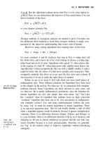
2.5.5—Coarse aggregate should consist of hard, dense, du-
rable, uncoated particles. Rock which is very friable or which
tends to degrade during processing, transporting, or in storage
should be avoided. Rock having an absorption greater than 3
percent or a specific gravity less than 2.5 is not generally con-
sidered suitable for exposed mass concrete subjected to freez-
ing and thawing. Sulfates and sulfides, determined by
chemical analysis and calculated as SO
3
, should not exceed
0.5 percent of the weight of the coarse aggregate. The percent-
age of other deleterious substances such as clay, silt, and fine
dust in the coarse aggregate as delivered to the mixer should
in general not exceed the values outlined in Table 2.5.5.
Fig. 2.5.5 shows a coarse aggregate rewashing screen at the
batch plant where dust and coatings accumulating from
stockpiling and handling can be removed to assure aggregate
cleanliness.
2.5.6—Theoretically, the larger the maximum aggregate
size, the less cement is required in a given volume of concrete
to achieve the desired quality. This theory is based on the fact
that with well-graded materials the void space between the par-
ticles (and the specific surface) decreases as the range in sizes
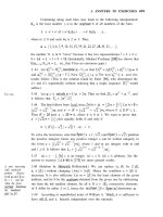
increases. However, it has been demonstrated (Fig. 2.5.6) that
to achieve the greatest cement efficiency there is an optimum
maximum size for each compressive strength level to be ob-
tained with a given aggregate and cement (Higginson, Wallace,
and Ore 1963). While the maximum size of coarse aggregate is
limited by the configuration of the forms and reinforcing steel,
in most unreinforced mass concrete structures these require-
ments permit an almost unlimited maximum aggregate size. In
addition to availability, the economical maximum size is there-
fore determined by the design strength and problems in pro-
cessing, batching, mixing, transporting, placing, and
consolidating the concrete. Large aggregate particles of irregu-
lar shape tend to promote cracking around the larger particles
because of differential volume change. They also cause voids
to form underneath them due to bleeding water and air accumu-
lating during placing of concrete. Although larger sizes have
been used on occasion, an aggregate size of 6 in. (150 mm) has
normally been adopted as the maximum practical size.
2.5.7—The particle shape of aggregates has some effect on
workability and consequently, on water requirement. Rounded
particles, such as those which occur in deposits of stream-worn
sand and gravel, provide best workability. However, modern
crushing and grinding equipment is capable of producing both
fine and coarse aggregate of entirely adequate particle shape
from quarried rock. Thus, in spite of the slightly lower water re-
quirement of natural rounded aggregates, it is seldom econom-
ical to import natural aggregates when a source of high quality
crushed aggregate is available near the site of the work. It is
necessary to determine that the crushing equipment and proce-
dures will yield a satisfactory particle shape. One procedure to
control particle shape is to specify that the flat and elongated
particles cannot exceed 20 percent in each size group. A flat
particle is defined as one having a ratio of width to thickness
greater than three, while an elongated particle is defined as one
having a ratio of length to width greater than three.
2.5.8—The proportioning of aggregates in the concrete
mixture will strongly influence concrete workability and
this is one factor that can readily be adjusted during con-
struction. To facilitate this, aggregates are processed into
and batched from convenient size groups. In United States
practice it is customary, for large-aggregate mass concrete,
to divide coarse aggregate into the fractional sizes listed in
Table 2.5.8 (Tuthill 1980).
Sizes are satisfactorily graded when one-third to one-half
of the aggregate within the limiting screens is retained on the
middle size screen. Also, it has been found that maintaining
the percent passing the
3
/
8
-in. (9.5-mm) sieve at less than 30
percent in the
3
/
4
in. to No. 4 (19 to 4.75 mm) size fraction
(preferably near zero if crushed) will greatly improve mass
concrete workability and response to vibration.
2.5.9—Experience has shown that a rather wide range of
material percentage in each size group may be used as listed
in Table 2.5.9. Workability is frequently improved by reduc-
ing the proportion of cobbles called for by the theoreticalFig. 2.5.5—Coarse aggregate rewashing
207.1R-11MASS CONCRETE
Table 2.5.8— Grading requirements for coarse
aggregate
Test sieve
size,
sq. mesh,
in. (mm)
Percent by weight passing designated test sieve
Cobbles
6-3 in.
(150 - 75 mm)
Coarse
3-1
1
/
2
in.
75 - 37.5 mm)
Medium
1
1
/
2
-
3
/
4
in.
37.5 - 19 mm)
Fine
3
/
4
- No. 4 in.
(19 - 4.75
mm)
7 (175) 100
6 (150) 90-100
4 (100) 20-45 100
3 (75) 0-15 90-100
2 (50) 0-5 20-55 100
1
1
/
2
(37.5)
0-10 90-100
1 (25) 0-5 20-45 100
3
/
4
(19)
1-10 90-100
3
/
8
(9.5)
0-5 30-55
No. 4 (4.75) 0-5
Table 2.5.9— Ranges in each size fraction of
coarse aggregate that have produced workable
concrete*
Maximum
size in
concrete,
in. (mm)
Percentage of cleanly separated coarse aggregate fractions
Cobbles
6-3 in.
(150-75
mm)
Coarse
3-1
1
/
2
in.
(75-37.5
mm)
Medium
1
1
/
2
-
3
/
4
in.
(37.5-19
mm)
Fine
3
/
4
-
3
/
8
(19-9.5
mm)
3
/
8
-No. 4
(9.5-4.75
mm)
6 (150) 20-30 20-32 20-30 12-20 8-15
3 (75) 20-40 20-40 15-25 10-15
1
1
/
2
(37.5) 40-55 30-35 15-25
3
/
4
(19) 30-70 20-45
*U.S. Bureau of Reclamation 1981.
gradings. When natural gravel is used, it is economically de-
sirable to depart from theoretical gradings to approximate as
closely as workability permits the average grading of material
in the deposit. Where there are extreme excesses or deficien-
cies in a particular size, it is preferable to waste a portion of
the material rather than to produce unworkable concrete. The
problem of waste usually does not occur when the aggregate
is crushed stone. With modern two- and three-stage crushing
it is normally possible to adjust the operation so that a work-
able grading is obtained. Unless finish screening is employed,
it is well to reduce the amount of the finest size of coarse ag-
gregate since that is the size of the accumulated undersize of
the larger sizes. However, finish screening at the batching
plant, on horizontal vibrating screens and with no intermedi-
ate storage, is strongly recommended for mass concrete coarse
aggregates. With finish screening there is little difficulty in
limiting undersize to 4 percent of the cobbles, 3 percent of the
intermediate sizes, and 2 percent of the fine coarse aggregates.
Undersize is defined as that passing a test screen having open-
ings five-sixths of the nominal minimum size of the aggregate
fraction. Undersize larger than this five-sixths fraction has no
measurable effect on the concrete (Tuthill 1943).
2.5.10—In some parts of the world “gap” gradings are used
in mass concrete. These are gradings in which the material in
one or more sieve sizes is missing. In United States practice,
continuous gradings are normally used. Gap gradings can be
used economically where the material occurs naturally gap-
graded. But comparisons which can be made between con-
cretes containing gap-graded aggregate and continuously
graded aggregate indicate there is no advantage in purposely
producing gap gradings. Continuous gradings produce more
workable mass concrete with somewhat lower slump, less wa-
ter, and less cement. Continuous gradings can always be pro-
duced from crushing operations. Most natural aggregate
deposits in the United States contain material from which ac-
ceptable continuous gradings can be economically prepared.
2.6—Water
2.6.1—Water used for mixing concrete should be free of
materials that significantly affect the hydration reactions of
portland cement (Steinour 1960). Water that is fit to drink
may generally be regarded as acceptable for use in mixing
concrete. Potability will preclude any objectionable content
of chlorides. However, chloride content tests should be made
on any questionable water if embedded metals are present.
Limits on total chloride for various constructions are con-
tained in ACI 201.2R. When it is desirable to determine
whether a water contains materials that significantly affect
the strength development of cement, comparative strength
tests should be made on mortars made with water from the
proposed source and with distilled water. If the average of the
results of these tests on specimens containing the water being
evaluated is less than 90 percent of that obtained with speci-
mens containing distilled water, the water represented by the
sample should not be used for mixing concrete. If a potential
water source lacking a service record contains amounts of im-
purities as large as 5000 ppm or more, then, to insure durable
concrete, tests for strength and volume stability (length
change) may also be advisable.
Each point represents an average of two 18 x 36-in. (450 x 900-mm)
and two 24 x 48-in. (600 x 1200-mm) concrete cylinders tested 1 yr
for both Grand Coulee and Clear Creek aggregates.
Maximum Size Aggregate, mm
9.5 19 38
75 150
3
/
8
3
/
4
1
1
/
2
36
Maximum Size Aggregate, in.
Cement Content, lb per cubic yard (kg/m
3
)
700
(415)
650
(386)
600
(356)
550
(326)
500
(297)
450
(267)
400
(237)
350
(208)
300
(178)
250
(148)
5550
5670
5430
3580
3120
220018901460
2
0
0
0
p
s
i
(
1
3
.
8
M
P
a
)
2
5
0
0
p
s
i
(
1
7
.
2
M
P
a
)
3
0
0
0
p
s
i
(
2
0
.
7
M
P
a
)
3
5
0
0
p
s
i
(
2
4
.
1
M
P
a
)
4
0
0
0
p
s
i
(
2
7
.
6
M
P
a
)
5520
5090
4690
4150
4
5
0
0
p
s
i
(
3
1
.
0
M
P
a
)
5
0
0
0
p
s
i
(
3
4
.
5
M
P
a
)
5
5
0
0
p
s
i
(
3
7
.
9
M
P
a
)
5850
65906700
6320
7050
6540
6060
5510
6
5
0
0
p
s
i
(
4
4
.
8
M
P
a
)
6
0
0
0
p
s
i
(
4
1
.
4
M
P
a
)
+
Fig. 2.5.6—Effect of aggregate size and cement content on
compressive strength at one year (adapted from Higginson,
Wallace, and Ore 1963)
207.1R-12 ACI COMMITTEE REPORT
2.6.2—Waters containing up to several parts per million of
ordinary mineral acids, such as hydrochloric acid or sulfuric
acid, can be tolerated as far as strength development is con-
cerned. Waters containing even small amounts of various
sugars or sugar derivatives should not be used as setting
times may be unpredictable. The harmfulness of such waters
may be revealed in the comparative strength tests.
2.7—Selection of proportions
2.7.1—The primary objective of proportioning studies for
mass concrete is to establish economical mixes of proper
strength, durability, and impermeability with the best combi-
nation of available materials that will provide adequate
workability for placement and least practical rise in temper-
ature after placement. Trial mix methods are generally used
following procedures in ACI 211.1, Appendix 5.
2.7.2—Selection of the water-cement ratio or water-ce-
mentitious material ratio will establish the strength, dura-
bility, and permeability of the concrete. There also must be
sufficient fine material to provide proper placeability. Ex-
perience has shown that with the best shaped aggregates of
6 in. (150 mm) maximum size, the quantity of cement-size
material required for workability is about 10 percent less
than for a concrete containing angular aggregates. Trial
mixes using the required water-cementitious material ratio
and the observed water requirement for the job materials
will demonstrate the cementitious material content that
may be safely used to provide the required workability
(Portland Cement Association 1979; Ginzburg, Zinchenko,
and Skuortsova 1966).
2.7.3—The first step in arriving at the actual batch weights
is to select the maximum aggregate size for each part of the
work. Criteria for this selection are given in Section 2.5. The
next step is to assume or determine the total water content
needed to provide required slump which may be as low as
1-
1
/
2
in. (38 mm) to 2 in. (50 mm). In tests for slump, aggre-
gate larger than 1
1
/
2
in. (38 mm) must be removed by prompt-
ly screening the wet concrete. For 6-in. (150 mm) maximum-
size aggregate, water contents for air-entrained, minimum-
slump concrete may vary from about 120 to 150 lb/yd
3
(71 to
89 kg/m
3
) for natural aggregates, and from 140 to 190 lb/yd
3
(83 to 113 kg/m
3
) for crushed aggregates. Corresponding wa-
ter requirements for 3 in. (76 mm) maximum-size aggregate
are approximately 20 percent higher. However, for strengths
above 4000 psi (28 MPa) at 1 year the 3-in. (75 mm) maxi-
mum-size aggregate may be more efficient. (See Figure
2.5.6).
2.7.4—The batch weight of the cement is determined by
dividing the total weight of the mixing water by the water-
cement ratio or, when workability governs, it is the mini-
mum weight of cement required to satisfactorily place the
concrete (see 2.7.2). With the batch weights of cement and
water determined and with an assumed air content of 3 to 5
percent, the remainder of the material is aggregate. The only
remaining decision is to select the relative proportions of fine
and coarse aggregate. The optimum proportions depend on
aggregate grading and particle shape, and they can be finally
determined only in the field. For 6-in. (150-mm) aggregate
concrete containing natural sand and gravel, the ratio of fine
aggregate to total aggregate by absolute volume may be as
low as 21 percent. With crushed aggregates the ratio may be
in the range 25 to 27 percent.
2.7.5—When a pozzolan is included in the concrete as a
part of the cementitious material, the mixture proportioning
procedure does not change. Attention must be given to the
following matters: (a) water requirement may change, (b)
early-age strength may become critical, and (c) for maxi-
mum economy the age at which design strength is attained
should be greater. Concrete containing most pozzolans gains
strength somewhat more slowly than concrete made with
only portland cement. However, the load on mass concrete is
generally not applied until the concrete is relatively old.
Therefore, mass concrete containing pozzolan is usually de-
signed on the basis of 90-day to one-year strengths. While
mass concrete does not require strength at early ages to per-
form its design function, most systems of construction re-
quire that the forms for each lift be anchored to the next
lower lift. Therefore, the early strength must be great enough
to prevent pullout of the form anchors. Specially designed
form anchors may be required to allow safe rapid turnaround
times for the forms, especially when large amounts of poz-
zolan are used or when the concrete is lean and precooled.
2.8—Temperature control
2.8.1—The four elements of an effective temperature
control program, any or all of which may be used for a par-
ticular mass concrete project, are: (1) cementitious material
content control, where the choice of type and amount of ce-
mentitious materials can lessen the heat-generating poten-
tial of the concrete; (2) precooling, where cooling of
ingredients achieves a lower concrete temperature as placed
in the structure; (3) postcooling, where removing heat from
the concrete with embedded cooling coils limits the temper-
ature rise in the structure; and (4) construction management,
where efforts are made to protect the structure from exces-
sive temperature differentials by knowledgeable employ-
ment of concrete handling, construction scheduling, and
construction procedures. The temperature control for a
small structure may be no more than a single measure, such
as restricting placing operations to cool periods at night or
during cool weather. On the other extreme, some projects
can be large enough to justify a wide variety of separate but
complementary control measures that additionally can in-
clude the prudent selection of a low-heat-generating cement
system including pozzolans; the careful production control
of aggregate gradings and the use of large-size aggregates in
efficient mixes with low cement contents; the precooling of
aggregates and mixing water (or the batching of ice in place
of mixing water) to make possible a low concrete tempera-
ture as placed; the use of air-entraining and other chemical
admixtures to improve both the fresh and hardened proper-
ties of the concrete; using appropriate block dimensions for
placement; coordinating construction schedules with sea-
sonal changes to establish lift heights and placing frequen-
cies; the use of special mixing and placing equipment to
quickly place cooled concrete with minimum absorption of
ambient heat; evaporative cooling of surfaces through water
curing; dissipating heat from the hardened concrete by cir-
207.1R-13MASS CONCRETE
culating cold water through embedded piping; and insulat-
ing surfaces to minimize thermal differentials between the
interior and the exterior of the concrete.
It is practical to cool coarse aggregate, somewhat more dif-
ficult to cool fine aggregate, and practical to batch a portion
or all of the added mixing water in the form of ice. As a re-
sult, placing temperatures of 50 F (10 C) and lower are prac-
ticable and sometimes specified. Lower temperatures are
obtainable with more difficulty. Injection of liquid nitrogen
into mix water has also been effectively used to lower con-
crete temperature for mass concrete work. In most cases a
placing temperature of less than 65 F (18 C) can be achieved
with liquid nitrogen injection. Cooled concrete is advanta-
geous in mixture proportioning since water requirement de-
creases as temperature drops. Specified placing temperatures
should be established by temperature studies to determine
what is required to satisfy the design. Guidance in cooling
systems for mass concrete can be found in ACI 207.4R.
2.8.2—The chief means for limiting temperature rise is
controlling the type and amount of cementitious materials.
The goal of concrete proportioning studies is to reach a ce-
mentitious material content no greater than is necessary for
the design strength. The limiting factor in reaching this low
cementitious material level is usually the need to use some
minimum amount of cement-sized particles solely to provide
workability in the concrete. Without the use of supplemental
workability agents—such as pozzolans, air-entraining, or
other chemical admixtures—a mass concrete project can ex-
perience a continuing struggle to maintain workability while
holding to the low cementitious material content that best
protects against cracking. The ASTM specification for Type
II portland cement contains an option which makes it possi-
ble to limit the heat of hydration to 70 cal/g (290 kJ/kg) at 7
days. Use of a pozzolan as a replacement further delays and
reduces heat generation. This delay is an advantage—except
that when cooling coils are used, the period of postcooling
may be extended. If the mixture is proportioned so that the
cementitious materials content is limited to not more than
235 lb/yd
3
(139 kg/m
3
), the temperature rise for most con-
cretes will not exceed 35 F (19 C). A complete discussion of
temperature control is given in Chapter 5.
CHAPTER 3—PROPERTIES
3.1—General
3.1.1—The design and construction of massive concrete
structures, especially dams, is influenced by site topography,
foundation characteristics, and the availability of suitable
materials of construction. Economy, second only to safety
requirements, is the most important single parameter to con-
sider. Economy may dictate the choice of type of structure
for a given site. Proportioning of the concrete is in turn gov-
erned by the requirements of the type of structure and such
properties as the strength, durability, and thermal properties.
For large structures extensive investigations of aggregates,
admixtures, and pozzolans are justified. Concrete mixture
investigations are necessary to determine the most economi-
cal proportions of selected ingredients to produce the desired
properties of the concrete. Within recent years an increasing
utilization has been made of finite element computer pro-
grams for thermal analysis (Polivka and Wilson 1976; U.S.
Army Corps of Engineers 1994). Determination of tensile
strain capacity has also lead to a better understanding of the
potential for cracking under rapid and slow loading condi-
tions (Houghton 1976).
3.1.2—The specific properties of concrete which should
be known are compressive strength, tensile strength, modu-
lus of elasticity, Poisson’s ratio, tensile strain capacity,
creep, volume change during drying, adiabatic temperature
rise, thermal coefficient of expansion, specific heat, thermal
conductivity and diffusivity, permeability, and durability.
Approximate values of these properties based on computa-
tions or past experience are often used in preliminary evalu-
ations. Useful as such approximations may be, the complex
heterogeneous nature of concrete and the physical and chem-
ical interactions of aggregate and paste are still not suffi-
ciently known to permit estimation of reliable values. For
this reason, it is again emphasized that extensive laboratory
and field investigations must be conducted to assure a safe
structure at lowest cost. In addition, the moisture condition
of the specimens and structure, and the loading rate required,
must be known, as these factors may dramatically affect
some concrete properties. Specimen size and orientation ef-
fects on mass concrete test properties can also be significant.
3.1.3—A compilation of concrete proportion data on rep-
resentative dams is given in Table 3.1.3 (Price and Higgin-
son 1963; Ginzburg, Zinchenko, and Skuortsova 1966;
ICOLD 1964; Harboe 1961; U.S. Bureau of Reclamation
1958; Houghton and Hall 1972; Houghton 1970; Houghton
1969). Reference will be made to concrete mixes described
in Table 3.1.3 in discussions of properties reported in Tables
3.2.1, 3.3.2, 3.4.2, 3.5.1, 3.7.1, and 3.8.1.
3.2—Strength
3.2.1—The water-cementitious material ratio to a large
extent governs the quality of the hardened portland cement
binder. Strength, impermeability, and most other desirable
properties of concrete are improved by lowering the water-
cementitious material ratio. A study of compressive strength
data given in Table 3.2.1 shows a considerable variation
from the direct relationship between water-cementitious ma-
terial ratio and strength. Factors, totally or partially indepen-
dent of the water-cementitious material ratio, which affect
the strength are: (1) composition and fineness of cement, (2)
amount and type of pozzolan, (3) surface texture and shape
of the aggregate, (4) the mineralogic makeup and strength of
the aggregate, (5) aggregate grading, and (6) the improve-
ment of strength by admixtures above that attributable to a
reduction in water-cementitious material ratio.
3.2.2—High strengths are usually not required in mass
concretes except in thin arch dams. Concrete proportioning
should determine the minimum cement content for adequate
strength to give greatest economy and minimum temperature
rise. Cement requirements for adequate workability and du-
rability rather than strength frequently govern the portland
cement content.
207.1R-14 ACI COMMITTEE REPORT
207.1R-15MASS CONCRETE
207.1R-16 ACI COMMITTEE REPORT
3.2.3—Mass concrete is seldom required to withstand
substantial stress at early age. Therefore, to take full advan-
tage of the strength properties of the cementing materials, the
design strength is usually based on the strength at ages from
90 days to one year; and sometimes up to two years. Job con-
trol cylinders must of necessity be tested at an earlier age if
they are to be useful in exercising control and maintaining
consistency during the progress of the construction. For the
sake of convenience, job control test specimens are usually 6
x 12-in. (150 x 300-mm) cylinders containing concrete wet
screened to 1
1
/
2
in. (37.5 mm) maximum size. It is important
that correlation tests be made well in advance of construction
to compare the strength of wet-screened concrete tested at
the control age with appropriate-size test specimens contain-
ing the full mass concrete tested at the design test age. The
strength of large test specimens will usually be only 80 to 90
percent of the strength of 6 x 12-in. (150 x 300-mm) cylin-
ders tested at the same age. Accounting for the continued
strength development beyond 28 days, particularly where
pozzolans are employed, the correlation factors at one year
may range from 1.15 to 3.0 times the strength of the wet-
screened control specimens tested at 28 days.
3.2.4—Accelerated curing procedures set forth in ASTM
C 684 yield compression test results in 24 to 48 hr that can
provide an indication of potential concrete strength. Howev-
er, the use of these procedures should be limited to detecting
variations in concrete quality and judging the effectiveness
of job control measures. The accelerated strength indicator is
helpful where satisfactory correlation has been established
with longer-term values using companion specimens of the
same concrete. Although the indicator may have dubious re-
lationship to the actual future strength in the concrete struc-
ture, it can be helpful during construction.
3.2.5—The factors involved in relating results of strength
tests on small samples to the probable strength of mass con-
crete structures are several and complex and still essentially
unresolved. Because of these complexities, concrete strength
requirements are usually several times the calculated maxi-
mum design stresses for mass concrete structures. For exam-
ple, design criteria for gravity dams commonly used by the
U.S. Bureau of Reclamation and the U.S. Army Corps of En-
gineers set the maximum allowable compressive stress for
usual loading combinations at one-third of the specified con-
crete strength. The selection of allowable stresses and factors
of safety depend on the structure type, loading conditions be-
ing analyzed, and the structure location (U.S. Bureau of Rec-
lamation 1976; U.S. Army Corps of Engineers 1990).
Table 3.2.1—Cement/water requirements and strengths of concrete in various dams
Dam Country
Cement or
cement-pozzolan,
lb/yd
3
(kg/m
3
)
Water,
lb/yd
3
(kg/m
3
)
Predominant
aggregate
type
Maximum
size aggregate,
in. (mm)
W/(C+P)
or W/C
90-day strength,
psi (MPa)
Cement efficiency
at 90 days,
psi/lb/yd
3
(MPa/kg/m
3
)
La Palisse
France 506 (300) 250 (148) Granite 4.7 (120) 0.49 4790 (33.0) 9.5 (0.111)
Chastang
France 379 (225) 169 (100) Granite 9.8 (250) 0.45 3770 (26.0) 9.9 (0.115)
L’Aigle
France 379 (225) 211 (125) Granite 9.8 (250) 0.56 3200 (22.1) 8.4 (0.098)
Pieve di Cadore
Italy 337 (200) 213 (126) Dolomite 4.0 (100) 0.63 6400 (44.1) 19.0 (0.220)
Forte Baso
Italy 404 (240) 238 (141) Porphyry 3.9 (98) 0.59 4920 (33.9) 12.2 (0.141)
Cabril
Portugal 370 (220) 195 (116) Granite 5.9 (150) 0.53 4150 (28.6) 11.2 (0.130)
Salamonde
Portugal 420 (249) 225 (133) Granite 7.9 (200) 0.54) 4250 (29.3) 10.1 (0.118)
Castelo Bode
Portugal 370 (220) 180 (107) Quartzite 7.9 (200) 0.49 3800 (26.2) 10.3 (0.119)
Rossens
Switz. 420 (249) 225 (133) Glacial mix 2.5 (64) 0.54 5990 (41.3) 14.3 (0.166)
Mauvoisin
Switz. 319 (189) 162 (96) Gneiss 3.8 (96) 0.51 4960 (34.2) 15.5 (0.181)
Zervreila
Switz. 336 (199) 212 (126) Gneiss 3.8 (96) 0.63 3850 (26.5) 10.5 (0.133)
Hungry Horse
USA 188-90 (111-53) 130 (77) Sandstone 6.0 (150) 0.47 3100 (21.4) 11.2 (0.130)
Glen Canyon
USA 188-94 (111-56) 153 (91) Limestone 6.0 (150) 0.54 3810 (26.3) 13.5 (0.160)
Lower Granite
USA 145-49 (86-29) 138 (82) Basalt 6.0 (150) 0.71 2070 (14.3) 10.7 (0.124)
Libby
USA 148-49 (88-29) 133 (79) Quartzite 6.0 (150) 0.68 2460 (17.0) 12.5 (0.145)
Dworshak
USA 211-71 (125-42) 164 (97) Granite 6.0 (150) 0.58 3050 (21.0) 10.8 (0.126)
Dworshak
USA 198-67 (117-40) 164 (97) Gneiss 6.0 (150) 0.62 2530 (17.4) 9.5 (0.111)
Dworshak
USA 168-72 (100-43) 166 (98) Gneiss 6.0 (150) 0.69 2030 (14.0) 8.5 (0.098)
Dworshak
USA 174-46 (130-27) 165 (98) Gneiss 6.0 (150) 0.75) 1920 (13.2) 8.7 (0.084)
Pueblo
USA 226-75 (134-44) 168 (100)
Granite
limestone
dolomite
3.5 (89) 0.56 3000* (20.7) 10.0 (0.116)
Crystal
USA 390 (231) 183 (109)
Shist and altered
volanics
3.0 (75) 0.47
4000
†
(27.6)
10.3 (0.119)
Flaming Gorge
USA 188-94 (111-56) 149 (88)
Limestone and
sandstone
6.0 (150) 0.53 3500 (24.1) 12.4 (0.144)
Krasnoiarsk
USSR 388 (230) 213 (126) Granite 3.9 (100) 0.55 3280 (22.6) 8.5 (0.098)
Ilha Solteira
Brazil 138-46 (82-27) 138 (82)
Quartzite gravel,
crushed basalt
6.0 (150) 0.75 3045 (21.0) 16.5 (0.193)
Itaipu
Brazil 182-22 (108 13) 143 (85) Crushed basalt 6.0 (150) 0.70 2610 (18.0) 12.8 (0.149)
Theo. Roosevelt
Modification
USA 270 (160) 144 (85) Granite 4.0 (100) 0.53 4500 (31.0) 16.7 (0.194)
* Strength at 180 days
† Strength at one yr
207.1R-17MASS CONCRETE
3.2.6—Concrete that is strong in compression is also
strong in tension but this strength relationship is not linear.
Tensile strength can be measured by several tests, primarily
direct tensile, splitting tensile, and modulus of rupture (flex-
ural) tests. Each of these tests has a different relationship
with compressive strength. An expression that relates tensile
strength, f
t
, to compressive strength, f
c
, is
for f
t
and f
c
in psi
f
t
= 1.7 f
c
2/3
for f
t
and f
c
in MPa
f
t
= 0.32 f
c
2/3
Raphael (1984) discussed these and other tensile-compres-
sive strength relationships, and their use in design. Relation-
ships of these types for specific materials can vary
significantly from the formulas above, based on aggregate
quality and many other factors. Where feasible and necessary,
testing should be conducted to confirm these relationships.
3.2.7—The strength of concrete is also influenced by the
speed of loading. Values usually reported are for static loads
that take appreciable time to develop, e.g. dead load or water
load. During earthquakes, however, stresses may be fully de-
veloped in a small fraction of a second. It has been found that
when loaded at this speed, compressive strength of a con-
crete for moist specimens may be increased up to 30 percent
and tensile strength may be increased up to 50 percent, when
compared to values obtained at standard rates of loading
(Saucier 1977; Graham 1978; Raphael 1984).
3.3—Elastic properties
3.3.1—Concrete is not a truly elastic material, and the
graphic stress-strain relationship for continuously increasing
load is generally in the form of a curved line. However, the
modulus of elasticity is for practical purposes considered a
constant within the range of stresses to which mass concrete
is usually subjected.
3.3.2—The moduli of elasticity of concrete representative
of various dams are given in Table 3.3.2. These values range
from 2.8 to 5.5 x 10
6
psi (1.9 to 3.8 x 10
4
MPa) at 28 days
and from 3.8 to 6.8 x 10
6
psi (2.6 to 4.7 x 10
4
MPa) at one
year. Usually, concretes having higher strengths have higher
values of elastic modulus and show a general correlation of
increase in modulus with strength, although modulus of elas-
ticity is not directly proportional to strength, since it is influ-
enced by the modulus of elasticity of the aggregate. In the
past, data from concrete modulus of elasticity tests showed
relatively high coefficient of variation resulting from at-
tempts to measure small strains on a heterogeneous mixture
Table 3.3.2— Compressive strength and elastic properties of mass concrete
No Dam
Compressive strength Elastic properties
psi
(MPa)
Modulus of elasticity, E x 10
6
psi
(E x 10
4
MPa) Poisson’s ratio
Age, days Age, days Age, days
28 90 180 365 28 90 180 365 28 90 180 365
1 Hoover
3030
(20.9)
3300
(22.8)
—
4290
(29.6)
5.5
(3.8)
6.2
(4.3)
—
6.8
(4.7)
0.18 0.20 — 0.21
2 Grand Coulee
4780
(33.0)
5160
(35.6)
—
5990
(41.3)
4.7
(3.2)
6.1
(4.2)
—
6.0
(4.1)
0.17 0.20 — 0.23
3 Glen Canyon
2550
(17.6)
3810
(26.3)
3950
(27.2)
—
5.4
(3.7)
—
5.8
(4.0)
— 0.11 — 0.14 —
3a Glen Canyon*
3500
(24.1)
4900
(33.8)
6560
(45.2)
6820
(47.0)
5.3
(3.7)
6.3
(4.3)
6.7
(4.6)
— 0.15 0.15 0.19 —
4 Flaming Gorge
2950
(20.3)
3500
(24.1)
3870
(26.7)
4680
(32.3)
3.5
(2.4)
4.3
(3.0)
4.6
(3.2)
— 0.13 0.25 0.20 —
5 Yellowtail —
4580
(31.6)
5420
(37.4)
5640
(38.9)
—
6.1
(4.2)
5.4
(3.7)
6.2
(4.3)
— 0.24 0.26 0.27
6 Morrow Point*
4770
(32.9)
5960
(41.1)
6430
(44.3)
6680
(46.1)
4.4
(3.0)
4.9
(3.4)
5.3
(3.7)
4.6
(3.2)
0.22 0.22 0.23 0.20
7 Lower Granite*
1270
(8.8)
2070
(14.3)
2420
(16.7)
2730
(18.8)
2.8
(1.9)
3.9
(2.7)
3.8
(2.6)
3.9
(2.7)
0.19 0.20 — —
8 Libby
1450
(10.0)
2460
(17.0)
—
3190
(22.0)
3.2
(2.2)
4.0
(2.8)
—
5.5
(3.8)
0.14 0.18 — —
9 Dworshak*
1200
(8.3)
2030
(14.0)
—
3110
(21.4)
—
3.7
(2.6)
—
3.8
(2.6)
— — — —
10 Ilha Solteira
2320
(16.0)
2755
(19.0)
3045
(21.0)
3190
(22.0)
5.1
(3.5)
5.9
(4.1)
— — 0.15 0.16 — —
11 Itaipu
1885
(13.0)
2610
(18.0)
2610
(18.0)
2755
(19.0)
5.5
(3.8)
6.2
(4.3)
6.2
(4.3)
6.5
(4.5)
0.18 0.21 0.22 0.20
12 Peace Site* 1
3060
(21.1)
3939
(27.2)
4506
(31.1)
4666
(32.2)
— — — — — — — —
13
Theodore Roosevelt
Modification
2400
(16.5)
4500
(31.0)
5430
(37.4)
5800
(40.0)
4.5
(3.1)
5.4
(3.7)
—
6.2
(4.3)
0.20 0.21 — 0.21
*Water-reducing agent used.
207.1R-18 ACI COMMITTEE REPORT
containing large-size aggregate. Modern electronic devices
such as the linear variable differential transformer (LVDT)
can measure small length changes with great accuracy. Ten-
sile modulus of elasticity is generally assumed to be identical
to the compressive modulus of elasticity.
3.3.3—Poisson’s ratio data given in Table 3.3.2 tend to
range between the values of 0.16 and 0.20 with generally
small increases with increasing time of cure. Extreme values
may vary from 0.11 to 0.27. Poisson’s ratio, like modulus of
elasticity, is influenced by the aggregate, the cement paste,
and relative proportions of the two.
3.3.4—The growth of internal microcracks in concrete
under load commences at compressive stresses equal to
about 35 to 50 percent of the nominal compressive strength
under short term loading. Above this stress, the overall vol-
umetric strain reflects the volume taken up by these internal
fissures, and Poisson’s ratio and the elastic moduli are no
longer constant.
3.3.5—The results of several investigations indicate that
the modulus of elasticity appears to be relatively unchanged
whether tested at normal or dynamic rates of loading (Hess
1992). Poisson’s ratio can be considered the same for normal
or dynamic rates of loading (Hess 1992).
3.4—Creep
3.4.1—Creep of concrete is partially-recoverable plastic
deformation that occurs while concrete is under sustained
stress. Creep appears to be mainly related to the modulus of
elasticity of the concrete. Concretes having high values of
modulus of elasticity generally have low values of creep de-
formation. The cement paste is primarily responsible for
concrete creep. With concretes containing the same type of
aggregate, the magnitude of creep is closely related to the
paste content (Polivka, Pirtz, and Adams 1963) and the wa-
ter-cementitious material ratio of the concrete. ACI 209R
discusses the prediction of creep, shrinkage, and temperature
effects in concrete structures.
3.4.2—One method of expressing the effect of creep is as
the sustained modulus of elasticity of the concrete in which
the stress is divided by the total deformation for the time un-
der the load. The instantaneous and sustained modulus of
elasticity values obtained on 6-in. (150-mm) diameter cylin-
ders made with mass-mixed concrete wet screened to 1
1
/
2
in.
(37.5 mm) maximum size, are recorded in Table 3.4.2. The
instantaneous modulus is measured immediately after the
concrete is subjected to load. The sustained modulus repre-
sents values after 365 and 1000 days under load. From Table
3.4.2 it can be seen that the sustained values for modulus are
approximately one-half that of the instantaneous modulus
when load is applied at early ages and is a slightly higher per-
centage of the instantaneous modulus when the loading age
is 90 days or greater. Creep of concrete appears to be approx-
imately directly proportional to the applied stress/strength
ratio up to about 40 percent of the ultimate strength of the
concrete.
3.5—Volume change
3.5.1—Volume changes are caused by changes in mois-
ture content of the concrete, changes in temperature, chemi-
cal reactions, and stresses from applied loads. Excessive
volume change is detrimental to concrete. Cracks are formed
in restrained concrete as a result of shrinkage or contraction
and insufficient tensile strength or strain capacity. Cracking
is a weakening factor that may affect the ability of the con-
crete to withstand its design loads and may also detract from
durability and appearance. Volume change data for some
mass concretes are given in Table 3.5.1. Various factors in-
fluencing cracking of mass concrete are discussed in Carl-
son, Houghton, and Polivka (1979).
Table 3.4.2— Elastic properties of mass concrete
Age at
time of
loading
Instantaneous and sustained modulus of elasticity,* psi x 10
6
(MPa x 10
4
)
Grand Coulee Shasta Hungry Horse Dworshak Libby
E E
1
E
2
E E
1
E
2
E E
1
E
2
E E
1
E
2
E E
1
E
2
2 days
1.7
(1.2)
0.83
(0.57)
0.76
(0.52)
1.4
(0.97)
0.54
(0.37)
0.49
(0.34)
2.8
(1.9)
1.5
(1.0)
1.4
(0.97)
1.4
(0.97)
0.75
(0.52)
0.70
(0.48)
1.6
(1.1)
1.0
(0.69)
0.9
(0.62)
7 days
2.3
(1.6)
1.1
(0.76)
1.0
(0.69)
2.1
(1.4)
1.0
(0.69)
0.96
(0.66)
4.2
(2.9)
1.9
(1.3)
1.8
(1.2)
2.0
(1.4)
1.0
(0.69)
0.90
(0.62)
3.2
(2.2)
1.6
(1.1)
1.3
(0.90)
20 days
3.5
(2.4)
1.8
(1.2)
1.6
(1.1)
3.5
(2.4)
1.8
(1.2)
1.6
(1.1)
4.5
(3.1)
2.6
(1.8)
2.4
(1.7)
2.8
(1.9)
1.4
(0.97)
1.3
(0.90)
4.1
(2.8)
2.2
(1.5)
2.0
(1.4)
90 days
4.1
(2.0)
2.5
(1.7)
2.3
(1.6)
4.4
(3.0)
2.7
(1.9)
2.5
(1.7)
5.2
(3.6)
3.2
(2.2)
3.0
(2.1)
3.8
(2.6)
2.2
(1.5)
2.0
(1.4)
5.2
(3.6)
2.9
(2.0)
2.7
(1.9)
1 yr
5.0
(3.4)
2.5
(1.7)
2.3
(1.6)
4.4
(3.0)
2.7
(1.9)
2.5
(1.7)
5.2
(3.6)
3.2
(2.2)
3.0
(2.1)
3.8
(2.6)
2.2
(1.5)
2.0
(1.4)
5.2
(3.6)
2.9
(2.0)
2.7
(1.9)
5 yr
5.3
(3.7)
3.6
(2.5)
3.4
(2.3)
5.9
(4.1)
4.0
(2.8)
3.8
(2.6)
4.9
(3.4)
3.0
(2.1)
2.9
(2.0)
6.4
(4.4)
4.3
(3.0)
4.1
(2.8)
7
1
/
4
yr
5.6
(3.9)
4.3
(3.0)
4.1
(2.8)
*All concretes mass mixed, wet screened to 1
1
/
2
in. (37.5 mm) maximum-size aggregate.
E = instantaneous modulus of elasticity at time of loading.
E
1
= sustained modulus after 365 days under load.
E
2
= sustained modulus after 1000 days under load.
Note: The instantaneous modulus of elasticity refers to the “static” or normal load rate (1 to 5 min duration) modulus, not a truly instantaneous modulus
measured from “dynamic” or rapid load rate testing.
207.1R-19MASS CONCRETE
3.5.2—Drying shrinkage ranges from less than 0.02 per-
cent (or 200 millionths) for low-slump lean concrete with
good quality aggregates to over 0.10 percent (or 200 mil-
lionths) for rich mortars or some concretes containing poor
quality aggregates and an excessive amount of water. The
principal drying shrinkage of hardened concrete is usually
occasioned by the drying and shrinking of the cement gel
which is formed by hydration of portland cement. The main
factors affecting drying shrinkage are the unit water content
and aggregate mineralogy and content. Other factors influ-
ence drying shrinkage principally as they influence the total
amount of water in mixtures. The addition of pozzolans gen-
erally increases drying shrinkage except where the water re-
quirement is significantly reduced, such as with fly ash.
Some aggregates, notably graywacke and sandstone, have
been known to contribute to extremely high drying shrink-
age. ACI 224R and Houghton (1972) discuss the factors in-
volved in drying characteristics of concrete.
3.5.3—Autogenous volume change results from the chem-
ical reactions within the concrete. Unlike drying shrinkage it
is unrelated to the amount of water in the mix. The net autog-
enous volume change of most concretes is a shrinkage of
from 0 to 150 millionths. When autogenous expansion oc-
curs it usually takes place within the first 30 days after plac-
ing. Concretes containing pozzolans may sometimes have
greater autogenous shrinkage than portland cement concrete
without pozzolans (Houk, Borge, and Houghton 1969).
3.5.4—The thermal coefficient of expansion of a concrete
depends mainly upon the type and amount of coarse aggre-
gate in the concrete. Various mineral aggregates may range
in thermal coefficients from below 2 millionths to above 8
millionths per deg F (3 to 14 millionths per deg C). Neat ce-
ment pastes will vary from about 6 millionths to 12 mil-
lionths per deg F (10 millionths to 21 millionths per deg C)
depending on the chemical composition and the degree of
hydration. The thermal coefficient of the concrete usually re-
flects the weighted average of the various constituents.
Sometimes coefficient of expansion tests are conducted on
concrete that has been wet screened to 1
1
/
2
in. (37.5 mm)
maximum size in order to work with smaller-size specimens.
However, the disproportionately larger amount of cement
paste, which has a higher coefficient, results in values higher
than that of the mass concrete. Concrete coefficients of ther-
mal expansion are best determined on specimens containing
the full concrete mix. Refer to values in Table 3.7.1.
3.5.5—The portland cement in concrete liberates heat
when it hydrates and the internal temperature of the con-
crete rises during this period (Dusinberre 1945; Wilson
1968). The concrete is relatively elastic during this early
stage, and it can be assumed to be at or near zero stress
when the maximum temperature is attained. When cooling
begins, the concrete is gaining strength and stiffness rapid-
ly. If there is any restraint against free contraction during
cooling, tensile strain and stress develop. The tensile stress-
es developed during the cooling stage are determined by
five quantities: (1) thermal differential and rate of temper-
ature change, (2) coefficient of thermal expansion, (3)
modulus of elasticity, (4) creep or relaxation, and (5) the
degree of restraint. If the tensile stress developed exceeds
the tensile strength of the concrete, cracking will occur
(Houghton 1972; Houghton 1976; Dusinberre 1945). Prin-
cipal methods utilized to reduce the potential for thermally
induced cracking in concrete are outlined in ACI 224R and
Carlson, Houghton, and Polivka (1979). They include re-
ducing the maximum internal temperature which the con-
crete attains; reducing the rate at which the concrete cools;
and increasing the tensile strength of the concrete. Concrete
resistance to cracking can be equated to tensile strain ca-
Table 3.5.1— Volume change and permeability of mass concrete
Structure
Autogenous volume change Drying shrinkage
Permeability,
K ft/s/ft*
hydraulic head m/s/m*
90 days,
millionths
1 yr,
millionths
1 yr,
millionths
Hoover — — - 270
1.97 x 10
-12
1.83 x 10
-13
Grand Coulee — — - 420 — —
Hungry Horse - 44 - 52 - 520
5.87 x 10
-12
5.45 x 10
-13
Canyon Ferry + 6 - 37 - 397
6.12 x 10
-12
5.69 x 10
-13
Monticello - 15 - 38 - 998
2.60 x 10
-11
2.42 x 10
-12
Clen Canyon - 32 - 61 - 459
5.74 x 10
-12
5.33 x 10
-13
Flaming Gorge — — - 496
3.52 x 10
-11
3.27 x 10
-12
Yellowtail - 12 - 38 - 345
6.25 x 10
-12
5.81 x 10
-13
Dworshak +10 - 8 - 510
6.02 x 10
-12
5.59 x 10
-13
Libby + 3 +12 - 480
1.49 x 10
-11
1.38 x 10
-12
Lower Granite + 4 + 4 —
Volume change specimens for Hoover and Grand Coulee Dams were 4 x 4 x 40-in. (100 x 100 x 1000-mm) prisms; for Dworshak, Libby,
and Lower Granite Dams volume change was determined on 9 x 18-in. (230 x 460-mm) sealed cylinders. Specimens for the other
dams tabulated were 4 x 4 x 30-in. (100 x 100 x 760-mm) prisms.
Specimens for permeability for Dworshak, Libby, and Lower Granite Dams were 6 x 6-in. (150 x 150-mm) cylinders. Specimens for per-
meability for the other dams tabulated were 18 x 18 in. (460 x 460 mm).
*ft/s/ft = ft
3
/ft
2
-s/ft of hydraulic head; m/s/m = m
3
/m
2
-s/m of hydraulic head; millionths = in. x 10
-6
/in. (mm x 10
-6
/mm), measured in lin-
ear length change.
207.1R-20 ACI COMMITTEE REPORT
Table 3.7.1—Thermal properties of concrete
Inch-pound units SI units
Structure
Coarse
aggregate type
Temperature,
F
Coefficient of
expansion,*
millionths/F
Thermal
conductivity,†
Btu
ft x hr x F
Coefficient of
expansion,*
millionths/C
Thermal
conductivity,†
kJ
m x hr x C
1
1
/
2
in.
max
4
1
/
2
in.
max
Specific heat,
Btu
lb x F
Density, lb
ft
3
Diffusivity,**
ft
2
hr
Temperature,
C 37.5 mm max 114 mm max
Specific heat kJ
kg x C
Density, kg
m
3
Diffusivity,**
x 10
-3
Hoover
Limestone and
granite
50
100
150
5.3 4.8
1.70
1.67
1.65
0.212
0.225
0.251
156.0
0.051
0.047
0.042
10
38
66
9.5 8.6
10.6
10.4
10.3
0.887
0.941
1.050
2500
4.7
4.4
3.9
Grand
Coulee
Basalt
50
100
150
4.4 4.6
1.08
1.08
1.09
0.219
0.231
0.257
158.1
0.031
0.029
0.027
10
38
66
7.9 8.3
6.74
6.74
6.78
0.916
0.967
1.075
2534
2.9
2.7
2.5
Friant
Quartzite gran-
ite and rhyolite
50
100
150
— —
1.23
1.23
1.24
0.216
0.230
0.243
153.8
0.037
0.035
0.033
10
38
66
— —
7.66
7.66
7.70
0.904
0.962
1.017
2465
3.4
3.2
3.1
Shasta
Andesite and
slate
50
100
150
— 4.8
1.32
1.31
1.31
0.219
0.233
0.247
156.6
0.039
0.036
0.034
10
38
66
— 8.6
8.20
8.16
8.16
0.916
0.975
1.033
2510
3.6
3.3
3.2
Angostura Limestone
50
100
150
4.0 —
1.49
1.48
1.46
0.221
0.237
0.252
151.2
0.045
0.041
0.038
10
38
66
7.2 —
9.29
9.20
9.08
0.925
0.992
1.054
2423
4.2
3.8
3.5
Kortes
Granite
gabbros and
quartz
50
100
150
5.2 4.5
1.61
1.60
1.59
0.208
0.221
0.234
151.8
0.050
0.047
0.044
10
38
66
9.4 8.1
10.0
9.96
9.87
0.870
0.925
0.979
2433
4.6
4.4
4.1
Hungry Horse Sandstone
50
100
150
6.2 5.7
1.72
1.71
1.69
0.217
0.232
0.247
150.1
0.053
0.049
0.046
10
38
66
9.7 9.4
10.1
10.0
9.87
0.895
0.937
0.983
2425
4.6
4.4
4.2
Monticello
Sandstone
metasiltstone
quartzite
rhyolite
50
100
150
5.2 —
1.57
1.55
1.53
0.225
0.237
0.250
151.3
0.046
0.043
0.040
10
38
66
9.4 —
9.79
9.67
9.54
0.941
0.992
1.046
2454
4.3
4.0
3.7
Anchor
Andesite, latite
and
limestone
50
100
150
5.6 4.5
1.14
1.14
1.15
0.227
0.242
0.258
149.0
0.034
0.032
0.030
10
38
66
10.1 8.1
7.11
7.11
7.15
0.950
1.013
1.079
2388
3.2
3.0
2.8
Glen
Canyon
Limestone, chert
and sandstone
50
100
150
— —
2.13
2.05
1.97
0.217
0.232
0.247
150.2
0.065
0.059
0.053
10
38
66
— —
13.3
12.8
12.3
0.908
0.971
1.033
2407
6.0
5.5
4.9
Flaming
Gorge
Limestone and
sandstone
50
100
150
— —
1.78
1.75
1.73
0.221
0.234
0.248
150.4
0.054
0.050
0.046
10
38
66
— —
11.1
10.9
10.8
0.925
0.979
1.038
2411
5.0
4.6
4.3
Yellowtail
Limestone and
andesite
50
100
150
— 4.3
1.55
1.52
1.48
0.226
0.239
0.252
152.5
0.045
0.042
0.039
10
38
66
— 7.7
9.67
9.46
9.20
0.946
1.000
1.054
2444
4.2
3.9
3.6
Libby
Natural quartz
gravel
100 6.5 6.0 2.24 0.220 152 0.067 36 11.7 10.8 13.9 0.920 2435 6.2
Dworshak Granite gneiss 100 — 5.5 1.35 0.220 154 0.040 36 — 9.9 8.41 0.920 2467 3.9
Ilha Solteira
Quartzite and
basalt
100 — 6.9 1.73 0.220 159 0.049 36 — 12.5 10.8 0.920 2552 4.6
Itaipu Basalt 100 — 4.3 1.06 0.233 158 0.029 36 — 7.8 6.61 0.975 2537 2.7
Theodore
Roosevelt
Modification
Granite
50
100
150
4.3 —
1.71
1.73
1.70
0.234
0.248
0.260
148.7
0.049
0.047
0.044
10
38
66
7.7 —
10.7
10.9
10.6
0.979
1.037
1.088
2380
4.6
4.4
4.1
*1
1
/
2
in. (37.5 mm) max and 4
1
/
2
in. (114 mm) max refer to maximum size of aggregate in concrete.
†Procedure for calculating thermal conductivity is described in CRD-44 (U.S. Army Corps of Engineers, 1949).
**Diffusivity is often expressed in ft
2
/day (m
2
/day) for convenience in calculations.
m
2
hr
207.1R-21MASS CONCRETE
pacity rather than to strength. When this is done, the aver-
age modulus of elasticity (sustained E) can be omitted from
the testing and computation requirements (ACI 207.2R;
Houghton 1976). Tensile strain capacity may be predicted
using compressive strength and the modulus of elasticity
(Liu and McDonald 1978). Thermal tensile strain capacity
of the concrete is measured directly in tests on concrete
made during the design stages of the project. Thermal ten-
sile strain developed in mass concrete increases with the
magnitude of the thermal coefficient of expansion, thermal
differential and rate of temperature change, and degree of
restraint (ACI 207.2R).
3.5.6—Volume changes can also result from chemical re-
actions, which can be potentially disruptive. These reactions
are discussed in 3.9.4.
3.6—Permeability
3.6.1—Concrete has inherently low permeability to water.
With properly proportioned mixtures that are compacted by
vibration, permeability is not a serious problem. Permeabili-
ty of concrete increases with increasing water-cementitious
material ratios (U.S. Bureau of Reclamation 1981). There-
fore, low water-cementitious material ratio and good consol-
idation and curing are the most important factors in
producing concrete with low permeability. Air-entraining
and other chemical admixtures permit the same workability
with reduced water content and therefore contribute to re-
duced permeability. Pozzolans usually reduce the permeabil-
ity of the concrete. Permeability coefficients for some mass
concretes are given in Table 3.5.1.
3.7—Thermal properties
3.7.1—Thermal properties of concrete are significant in
connection with keeping differential volume change at a
minimum in mass concrete, extracting excess heat from the
concrete, and dealing with similar operations involving heat
transfer. These properties are specific heat, conductivity, and
diffusivity. The main factor affecting the thermal properties
of a concrete is the mineralogic composition of the aggregate
(Rhodes 1978). Since the selection of the aggregate to be
used is based on other considerations, little or no control can
be exercised over the thermal properties of the concrete.
Tests for thermal properties are conducted only for providing
constants to be used in behavior studies as described in
Chapter 5. Specification requirements for cement, pozzolan,
percent sand, and water content are modifying factors but
with negligible effect on these properties. Entrained air is an
insulator and reduces thermal conductivity, but other consid-
erations which govern the use of entrained air outweigh the
significance of its effect on thermal properties. Some rock
types, such as granite, can have a rather wide range of ther-
mal properties depending upon their source. Quartz aggre-
gate is particularly noted for its high value of thermal
conductivity. Thermal property values for some mass con-
cretes are given in Table 3.7.1. Thermal coefficient of expan-
sion is discussed in Section 3.5.4.
3.8—Shear properties
3.8.1—Although the triaxial shear strength may be deter-
mined as one of the basic design parameters, the designer
usually is required to use an empirical relationship between
the shear and compressive strength of concrete. Shear prop-
erties for some concretes containing 1
1
/
2
-in. (37.5 mm) max-
imum-size aggregates are listed in Table 3.8.1. These
include compressive strength, cohesion, and coefficient of
internal friction, which are related linear functions deter-
mined from results of triaxial tests. Linear analysis of triaxial
results gives a shear strength slightly above the value ob-
tained from standard push-off tests. Past criteria have stated
that the coefficient of internal friction can be taken as 1.0 and
cohesion as 10 percent of the compressive strength (U.S. Bu-
reau of Reclamation 1976). More recent investigation has
concluded that assuming this level of cohesion may be un-
conservative (McLean & Pierce 1988).
3.8.2—The shear strength relationships reported can be
linearly analyzed using the Mohr envelope equation
Y = C + X tan
φ
in which C (unit cohesive strength or cohesion) is defined as
the shear strength at zero normal stress. Tan
φ, which is the
slope of the line, represents the coefficient of internal fric-
Table 3.8.1— Shear properties of concrete**
Dam
Age,
days W/C
Compressive
strength Cohesion
Tan ø
S
s
/S
c
§
psi MPa psi MPa
Grand
Coulee
28
28
28
90
112
365
0.52.
0.58
0.64
0.58
0.58
0.58
5250
4530
3810
4750
4920
8500
36.2
31.2
26.3
32.8
33.9
58.6
1170
1020
830
1010
930
1880
8.1
7.0
5.7
7.0
6.4
13.0
0.90
0.89
0.92
0.97
1.05
0.91
0.223
0.225
0.218
0.213
0.189
0.221
Hungry
Horse
104
144
622
0.55*
0.55*
0.60*
2250
3040
1750
15.5
21.0
12.1
500
680
400
3.4
4.7
2.8
0.90
0.89
0.86
0.222
0.224
0.229
Monti-
cello
28
40
0.62*
0.92*
2800
4120
19.3
28.4
610
950
4.2
6.6
0.93
0.85
0.218
0.231
Shasta
28
28
90
90
90
245
0.50
0.60
0.50
0.50
0.60
0.50
5740
4920
5450
6590
5000
6120
39.6
33.9
37.6
45.4
34.5
42.2
1140
1060
1090
1360
1040
1230
7.9
7.3
7.5
9.4
7.2
8.5
1.05
0.95
1.05
1.01
1.00
1.04
0.199
0.215
0.200
0.206
0.208
0.201
Dwor-
shak
180†
180†
180†
200‡
0.59*
0.63*
0.70*
0.59*
4150
3220
2420
2920
28.6
22.2
16.7
20.1
1490
1080
950
720
10.3
7.4
6.6
5.0
0.44
0.46
0.43
0.84
0.359
0.335
0.393
0.247
*W/C+P.
All test specimens 6 x 12 in. (150 x 300 mm) with dry, 1
1
/
2
in. (37.5
mm) maximum-size aggregate except † designates 3 x 6 in. (75 x
150 mm) test specimens sealed to prevent drying with
3
/
4
in. (19
mm) maximum-size aggregate and ‡ designates 18 x 36 in. (450 x
900 mm) test specimens sealed to prevent drying, with 6 in. (150
mm) maximum-size aggregate.
§Cohesion divided by compressive strength.
**Triaxial tests.
207.1R-22 ACI COMMITTEE REPORT
tion. X and Y are normal and shear stresses, respectively. In
many cases, the shear strengths in Table 3.8.1 were higher
for specimens of greater age; however, no definite trend is in
evidence. The ratio of triaxial shear strength to compressive
strength varies from 0.19 to 0.39 for the various concretes
shown. When shear strength is used for design, the test con-
fining pressures used should reflect anticipated conditions in
the structure. Whenever possible, direct shear tests on both
parent concrete and on jointed concrete should be conducted
to determine valid cohesion and coefficient of internal fric-
tion values for design.
3.8.3—Bonded horizontal construction joints may have
shear strength comparable to that of the parent concrete. Un-
bonded joints typically have lower cohesion, but the same
coefficient of internal friction, when compared to the parent
concrete. If no tests are conducted, the coefficient of internal
friction can be taken at 1.0 and the cohesion as 0, for unbond-
ed joints. For bonded joints, the coefficient of internal fric-
tion can be taken as 1.0, while the cohesion may approach
that of the parent concrete (McLean & Pierce 1988).
3.9—Durability
3.9.1—A durable concrete is one which will withstand the
effects of service conditions to which it will be subjected,
such as weathering, chemical action, alkali-aggregate reac-
tions, and wear (U.S. Bureau of Reclamation 1981). Labora-
tory tests can indicate relative durabilities of concretes, but it
is not generally possible to directly predict durability in field
service from laboratory durability studies.
3.9.2—Disintegration of concrete by weathering is caused
mainly by the disruptive action of freezing and thawing and
by expansion and contraction under restraint, resulting from
temperature variations and alternate wetting and drying. En-
trained air improves the resistance of concrete to damage
from frost action and should be specified for all concrete
subject to cycles of freezing and thawing while critically sat-
urated. Selection of good materials, use of entrained air, low
water-cementitious material ratio, proper proportioning,
placement to provide a watertight structure, and good water
curing usually provide a concrete that has excellent resis-
tance to weathering action.
3.9.3—Chemical attack occurs from (1) exposure to acid
waters, (2) exposure to sulfate-bearing waters, and (3) leach-
ing by mineral-free waters as explained in ACI 201.2R.
No type of portland cement concrete is very resistant to at-
tack by acids. Should this type of exposure occur the con-
crete is best protected by surface coatings.
Sulfate attack can be rapid and severe. The sulfates react
chemically with the hydrated lime and hydrated tricalcium
aluminate in cement paste to form calcium sulfate and calci-
um sulfo-aluminates. These reactions are accompanied by
considerable expansion and disruption of the concrete. Con-
crete containing cement low in tricalcium aluminate (ASTM
Types II, IV and V) is more resistant to attack by sulfates.
Hydrated lime is one of the products formed when cement
and water combine in concrete. This lime is readily dissolved
in pure or slightly acid water, which may occur in high
mountain streams. Pozzolans, which react with lime liberat-
ed by cement hydration, can prevent the tendency of lime to
leach from concrete. Surfaces of tunnel linings, retaining
walls, piers, and other structures are often disfigured by lime
deposits from water seeping through cracks, joints, and inter-
connected voids. With dense, low-permeability concrete,
leaching is seldom severe enough to impair the serviceability
of the structure.
3.9.4—Alkali-aggregate reaction is the chemical reaction
between alkalies (sodium and potassium) from portland ce-
ment or other sources and certain constituents of some aggre-
gates, which under certain conditions produces deleterious
expansion of the concrete. These reactions include alkali-sil-
ica reaction and alkali-carbonate rock reaction, discussed in
an Engineer Manual (U.S. Army Corps of Engineers 1994).
Where it is necessary to use an aggregate containing reactive
constituents, low-alkali cement should be specified. Also, as
further insurance against alkali-aggregate reaction, a suitable
pozzolan should be specified in sufficient quantity to control
deleterious reaction. Fly ash is generally considered less ef-
fective in controlling alkali-silica reaction and expansion
than are Class N pozzolans.
3.9.5—The principal causes of erosion of concrete surfac-
es are cavitation and the movement of abrasive material by
flowing water. Use of concrete of increased strength and
wear resistance offers some relief but the best solution lies in
the prevention, elimination, or reduction of the causes by
proper design, construction, and operation of the concrete
structure (ACI 210R). The use of aeration in high velocity
flows is an effective way to prevent cavitation.
CHAPTER 4—CONSTRUCTION
4.1—Batching
4.1.1—Proper batching of mass concrete requires little
that is different from the accurate, consistent, reliable batch-
ing that is essential for other classes of concrete. ACI 221R
covers the processing, handling, and quality control of ag-
gregate. ACI 304R discusses the measuring, mixing, trans-
porting, and placing of concrete.
4.1.2—The desirability of restricting the temperature rise
of mass concrete by limiting the cement content of the mix
creates a continuing construction problem to maintain work-
ability in the plastic concrete. Efficient mixes for mass con-
crete contain unusually low portions of cementing materials,
sand, and water. Thus the workability of these mixes for con-
ventional placement is more than normally sensitive to varia-
tions in batching. This problem can be lessened by the use of
efficient construction methods and modern equipment. Usu-
ally the production of large quantities of mass concrete is like
an assembly-line operation, particularly in dam construction,
where the performance of repetitive functions makes it eco-
nomically prudent to employ specialty equipment and effi-
cient construction methods. Consistency in the batching is
improved by: (1) finish screening of coarse aggregate at the
batching plant, preferably on horizontal vibrating screens
without intermediate storage, (2) refinements in batching
equipment, such as full-scale springless dials which register
all stages of the weighing operation, (3) automatic weighing
and cutoff features, (4) interlocks to prevent recharging when
some material remains in a scale hopper, (5) a device for in-
207.1R-23MASS CONCRETE
stant reading of approximate moisture content of sand, (6)
graphic or digital recording of the various weighing and mix-
ing operations, and (7) equipment capable of instant automat-
ic selection and setting of at least 11 different batch
ingredients in as many different mix proportions. In large
central plant mixers, the large batches commonly used for
mass concrete also tend to minimize the effect of variations.
4.1.3—Since greater use is made in mass concrete of such
special-purpose ingredients as ice, air-entraining, water-re-
ducing and set-controlling admixtures, and fly ash or other
pozzolans, the dependable, accurate batching of these materi-
als has become a very important aspect of the concrete plant.
For most efficient use of ice, its temperature must be less than
32 F (0 C) and it must be brittle-hard, dry, and finely broken.
For maximum efficiency ice should be batched by weighing
from a well-insulated storage bin, with quick discharge into
the mixer along with the other ingredients. Pozzolan and
ground iron blast-furnace slag are batched the same as cement.
4.1.4—Liquid admixtures are generally batched by vol-
ume, although weighing equipment has also been used suc-
cessfully. Reliable admixture batching equipment is
available from some admixture or batch plant manufacturers.
Means should be provided for making a visual accuracy
check. Provisions should be made for preventing batching of
admixture while the discharge valve is open. Interlocks
should also be provided that will prevent inadvertent over-
batching of the admixture. Particularly with air-entraining
and water-reducing admixtures, any irregularities in batch-
ing can cause troublesome variation in slump and/or air con-
tent. When several liquid admixtures are to be used, they
should be batched separately into the mixer. The use of com-
paratively dilute solutions reduces gumming in the equip-
ment. For continuing good operation, equipment must be
maintained and kept clean. Timed-flow systems should not
be used. Also, it is important to provide winter protection for
storage tanks and related delivery lines where necessary.
4.1.5—Batching tolerances frequently used are shown in
Table 4.1.5.
4.2—Mixing
4.2.1—Mixers for mass concrete must be capable of dis-
charging low-slump concrete quickly and with consistent dis-
tribution of large aggregate throughout the batch. This is best
accomplished with large tilting mixers in stationary central
plants. The most common capacity of the mixer drum is 4 yd
3
(3 m
3
) but good results have been achieved with mixers as
small as 2 yd
3
(1.5 m
3
) and as large as 12 yd
3
(9 m
3
). Truck
mixers are not suited to the mixing and discharging of low-
slump, large-aggregate concrete. Turbine-type mixers may be
used for mass concrete containing 3-in. (75-mm) aggregate.
4.2.2—Specifications for mixing time range from a mini-
mum of 1 min for the first cubic yard plus 15 sec for each ad-
ditional cubic yard (80 sec for first m
3
plus 20 sec for each
additional m
3
) of mixer capacity (ACI 304R and ASTM C
94) to 1
1
/
2
min for the first 2 yards plus 30 sec for each addi-
tional yard (1
1
/
2
min for the first 1
1
/
2
m
3
plus 40 sec for each
additional m
3
) of capacity (U.S. Bureau of Reclamation
1981). Blending the materials by ribbon feeding during
batching makes it possible to reduce the mixing period.
Some of the mixing water and coarser aggregate should lead
other materials into the mixer to prevent sticking and clog-
ging. Mixing times should be lengthened or shortened de-
pending upon the results of mixer performance tests. Criteria
for these tests are found in ASTM C 94, Annex, Table A1.1.
Mixing time is best controlled by a timing device which pre-
vents release of the discharge mechanism until the mixing
time has elapsed.
4.2.3—During mixing, the batch must be closely observed
to assure the desired slump. The operator and inspector must
be alert and attentive. Tuthill (1950) has discussed effective
inspection procedures and facilities. Preferably the operator
should be stationed in the plant where he can see the batch in
the mixer and be able to judge whether its slump is correct.
If the slump is low, perhaps due to suddenly drier aggregate,
he can immediately compensate with a little more water and
maintain the desired slump. Lacking this arrangement to see
into the mixer, he should be able to see the batch as it is dis-
charged. From this he can note any change from former
batches and make subsequent water adjustments according-
ly. A sand moisture meter will assist in arriving at the appro-
priate quantitative adjustment.
4.2.4—Continuous batching and mixing (pugmill) has
been used successfully in roller-compacted concrete for
years, and has also been used for traditional mass concrete
with satisfactory performance. Generally the maximum ag-
gregate size for this method is limited to 3 in. (75 mm) or
possibly 4 in. (100 mm). ACI 207.5R and ACI 304R discuss
continuous batching and mixing in more detail.
Table 4.1.5— Typical batching tolerances
Batch weights
greater than 30 percent of
scale capacity
less than 30 percent of
scale capacity
Ingredient
Batching
Individual Cumulative Individual Cumulative
Cement and
other
cementitious
materials
± 1 percent of specified
weight, or ± 1 percent of
scale capacity, whichever is
greater
not less than required weight
nor more than 4 percent over
required weight
Water (by
volume or
weight),
percent
± 1
Not
recommended
± 1
Not
recommended
Aggregates,
percent
± 2 ± 1 ± 2
± 3 percent of
scale capacity
or ± 3
percent of
required
cumulative
weight, which-
ever
is less
Admixtures
(by volume or
weight),
percent
± 3*
Not
recommended
± 3*
Not
recommended
*or ± 1fl oz (30 mL), whichever is greater.
207.1R-24 ACI COMMITTEE REPORT
the joint area and all rock clusters at batch-dump perimeters
are carefully scattered.
4.3.5—Selection of equipment for transporting and placing
of mass concrete is strongly influenced by the maximum size
of the aggregate. Concrete for mass placements such as in
dams often contains cobbles, which are defined as coarse ag-
gregate particles larger than 3 in. (75 mm) and smaller than 12
in. (300 mm). The tendency of cobbles to segregate from the
mix as a result of their greater inertia when in motion may dic-
tate the use of large, 2 to 12-yd
3
(1.5 to 9-m
3
) capacity buckets.
Railcars, trucks, cableways, or cranes, or some combination of
these, may be used to deliver the buckets to the point of place-
ment. For concrete containing coarse aggregate 3 in. (75 mm)
and larger, a bucket size of 4 to 8 yd
3
(3 to 6 m
3
) is preferable,
since smaller buckets do not discharge as readily, and each de-
livery is too small to work well with a high-production place-
ment scheme. On the other hand, the 12-yd
3
(9-m
3
) bucket puts
such a large pile in one place that much of the crew's time is de-
voted to vibrating for spreading instead of for consolidation.
To preclude these piles being larger than 4 yd
3
(3 m
3
), one
agency requires controllable discharge gates in buckets carry-
4.3—Placing
4.3.1—Placing includes preparation of horizontal con-
struction joints, transportation, handling, placement, and con-
solidation of the concrete (ACI SP-6 1963; ACI 304R; U.S.
Bureau of Reclamation 1981; Tuthill 1950; Tuthill 1953).
4.3.2—Efficient and best preparation of horizontal joint sur-
faces begins with the activities of topping out the lift. The sur-
face should be left free from protruding rock, deep footprints,
vibrator holes, and other surface irregularities. In general, the
surface should be relatively even with a gentle slope for drain-
age. This slope makes the cleanup easier. As late as is feasible
but prior to placement of the next lift, surface film and contam-
ination should be removed to expose a fresh, clean mortar and
aggregate surface. Overcutting to deeply expose aggregate is
unnecessary and wasteful of good material. Strength of bond
is accomplished by cement grains, not by protruding coarse
aggregate. Joint shear strength is determined both by this bond
and by interface friction. The friction contribution is affected
by confining pressure and coarse aggregate interlock. Usually
removal of only about 0.1 in. (a few millimeters) of inferior
material will reveal a satisfactory surface.
4.3.3—The best methods of obtaining such a clean surface
are by means of sandblasting (preferably wet sandblasting to
avoid dust hazard) or high-pressure water jet of at least 6000
psi (41.4 MPa). Operators must be on guard to avoid harm to
other personnel, to wooden surfaces, etc., from water-blasted
pieces of surface material, which may be hurled forward with
great force and velocity. Sandblasting has the advantage that
it will do the job at any age the concrete may be, but requires
handling of sandblast sand and equipment and its removal af-
ter use. The water-jet method leaves relatively little debris for
cleanup and removal, but may not work as efficiently after the
concrete is more than one week old. Before and after horizon-
tal construction joint cleanup with sandblasting and high-
pressure water blasting are illustrated in Fig. 4.3.3(a) and
4.3.3(b), respectively. Clean joints are essential to good bond
and watertightness. “Green cutting,” which is the early re-
moval of the surface mortar with an air-water jet about the
time the concrete approaches final set, is also used. However,
it may not be possible to preserve the initially clean surface
until concrete is placed upon it. The initially acceptable sur-
face may become dull with lime coatings or can become con-
taminated to such an extent that it may be necessary to use
sandblasting or high-pressure water jets to reclean it.
4.3.4—The clean concrete surface should be approaching
dryness and be free from surface moisture at the time new
concrete is placed on it (U.S. Army Corps of Engineers 1959,
1963, and 1966). Testing has shown superior strength and
watertightness of joints that are dry and clean when the over-
lying concrete is placed; then no water is present to dilute and
weaken the cement paste of the plastic concrete at the con-
struction joint. Tests have also shown that the practice of
placing mortar on the joint ahead of the concrete is not neces-
sary for either strength or impermeability of the joint (Hough-
ton and Hall 1972). The mortar coat, although widely used in
the past, is no longer commonly used in mass concrete work.
Equivalent results can be obtained without the mortar if the
first layer of the plastic concrete is thoroughly vibrated over
(a) Sandblast treatment
Fig. 4.3.3(a) and (b)—Before and after horizontal construc-
tion joint cleanup
(b) High-pressure water-blast treatment
207.1R-25MASS CONCRETE
ing more than 4 yd
3
(3 m
3
). Extra care must be taken to assure
ample vibration deep in the center of these piles and at points
of contact with concrete previously placed. Mass concrete of
proper mixture proportions and low slump does not separate
by settlement during such transportation over the short dis-
tances usually involved. However, care must be taken to pre-
vent segregation at each transfer point.
4.3.6—Mass concrete may also be transported in dumping
rail cars and trucks and placed by use of conveyors. Placing
mass concrete with conveyors has been most successful and
economical when the aggregate size is 4 in. (100 mm) or less.
The point of discharge from conveyors must be managed so
that concrete is discharged onto fresh concrete and immediate-
ly vibrated to prevent “stacking.” Placement of mass concrete
by conveyor is shown in Fig. 4.3.7. Additional information on
placing concrete with conveyors is contained in ACI 304.4R.
4.3.7—Large building foundations and other very large
monolithic concrete structures are mass concrete. Availabili-
ty and job conditions may preclude the use of preferable ag-
gregates larger than 1
1
/
2
in. (37.5 mm) or specialized
placement equipment. Concrete in such structures may be
placed with more conventional equipment such as smaller
crane buckets, concrete pumps, or conveyors. The selection
of placing equipment should be predicated upon its ability to
successfully place concrete which has been proportioned for
mass concrete considerations as defined in Section 2.7, which
emphasizes the reduction of heat evolution. It is important
that placing capacity be great enough to avoid cold joints and
undesirable exposure to extremes of heat and cold at lift sur-
faces. This is usually accomplished by utilizing many pieces
of placing equipment. Additional information on pumping of
concrete is contained in ACI 304.2R.
4.3.8—Mass concrete is best placed in successive lay-
ers. The maximum thickness of the layer depends upon the
ability of the vibrators to properly consolidate the concrete.
Six-in. (150-mm) diameter vibrators produce satisfactory re-
sults with 4 to 6-in. (100 to 150-mm) nominal maximum size
aggregate (NMSA) and less than 1
1
/
2
in. (40-mm) slump in
layers 18 to 20 in. (460 to 510 mm) thick placed with 4 to 8-
yd
3
(3 to 6-m
3
) buckets. Smaller diameter vibrators will pro-
duce satisfactory results with 3 to 4-in. (75 to 100-mm)
NMSA and less than 2-in. (50-mm) slump placed in 12 to 15-
in. (300 to 380-mm) layers with smaller buckets. Shallower
layers, rather than deeper layers, give better assurance of sat-
isfactory consolidation and freedom from rock pockets at
joint lines, corners, and other form faces, as well as within
the block itself.
4.3.9—The layer thickness should be an even fraction of
the lift height or of the depth of the block. The layers are car-
ried forward in a stair-step fashion in the block by means of
successive discharges so there will be a setback of about 5 ft
(1.5 m) between the forward edges of successive layers.
Placement of the steps is organized so as to expose a mini-
mum of surface and to lessen warming of the concrete in
warm weather and reduce the area affected by rain in wet
weather. A setback greater than 5 ft (1.5 m) unnecessarily
exposes cold concrete to heat gain in warm weather and, in
rainy weather, increases the danger of water damage; a nar-
rower setback will cause concrete above it to sag when the
step is vibrated to make it monolithic with the concrete
placed later against that step. This stepped front progresses
forward from one end of the block to the other until the form
is filled and the lift placement is completed.
4.3.10—Vibration is the key to the successful place-
ment of mass concrete, particularly when the concrete is
low slump and contains large aggregate (Tuthill 1953).
Ineffectual equipment is more costly to the builder be-
cause of a slower placing rate and the hazard of poor con-
solidation. Vibration must be systematic and should
thoroughly cover and deeply penetrate each layer. Partic-
Fig. 4.3.7—Placement of mass concrete by conveyor belt