autocad workbook for architects and engineers
Bạn đang xem bản rút gọn của tài liệu. Xem và tải ngay bản đầy đủ của tài liệu tại đây (24.42 MB, 298 trang )
AutoCAD Workbook for
Architects and Engineers
Shannon R Kyles
Professor
of
Architecture
Mohawk College, Ontario, Canada
• A Blackwell
II
Publishing
More free ebooks :
More free ebooks :
AutoCAD Workbook for
Architects and Engineers
Shannon R Kyles
Professor
of
Architecture
Mohawk College, Ontario, Canada
• A Blackwell
II
Publishing
More free ebooks :
This edition first published 2008
© 2008 by S.R. Kyles
Blackwell Publishing was acquired by John Wiley
& Sons in February 2007. Blackwell's publishing programme
has been merged with Wiley's global Scientific, Technical, and Medical business to form Wiley-Blackwell.
Registered office
John Wiley
& Sons Ltd, The Atrium, Southern Gate, Chichester, West Sussex, PO
19
8SQ, United Kingdom
Editorial office
9600 Garsington Road, Oxford, OX4 2DQ, United Kingdom
For details
of
our global editorial offices, for customer services and for information about how to apply for
permission to reuse the copyright material in this book please see
our
website at
www.wiley.comlwiley-blackwell.
The right
of
the author to be identified as the author
of
this work has been asserted in accordance with the
Copyright, Designs and Patents Act 1988.
All rights reserved. No part
of
this publication may be reproduced, stored in a retrieval system,
or
transmitted,
in any form
or
by
any means, electronic, mechanical, photocopying, recording or otherwise, except as
permitted by the
UK
Copyright, Designs and Patents Act
1988,
without the prior permission
of
the publisher.
Wiley also publishes its books
in
a variety
of
electronic formats. Some content that appears in print may not be
available in electronic books.
Designations used by companies to distinguish their products are often claimed
as
trademarks. All brand
names and product names used in this book are trade names, service marks, trademarks or registered
trademarks
of
their respective owners. The publisher is not associated with any product or vendor mentioned in
this book. This publication
is
designed
to
provide accurate and authoritative information in regard to the
subject mattercovered.
It
is sold on the understanding that the publisher
is
not engaged in rendering
professional services.
If
professional advice or other expert assistance is required, the services
of
a competent
professional should be sought.
Certain images and materials contained in this publication were reproduced with the permission
of
Autodesk,
Inc.
© 1999-2007 All rights reserved. Autodesk, AutoCAD, and AutoCAD
LT
are registered trademarks or
trademarks
of
Autodesk, Inc., in the U.SA., Canada, and certain other countries.
Library
of
Congress Cataloging-in-Publication Data
Kyles, Shannon.
AutoCAD workbook for architects
I S.R. Kyles.
p.em.
Includes index.
ISBN-13: 978-1-4051-8096-2 (pbk. : alk. paper)
ISBN-I0: 1-4051-8096-X (pbk. : alk. paper) I. Architectural drawing-Computer-aided
design-Handbooks, manuals, etc.
2.
AutoCAD-Handbooks, manuals, etc.
1.
Title.
NA2728.K952008
720.28'40285536 dc22
2007033120
A catalogue record for this book is available from the British Library.
Set in Times New Roman 101l3pt by S.R. Kyles, Canada
Printed in Singapore by C.O.S. Printers Pte Ltd
12008
More free ebooks :
Contents
Acknowledgments
Introduction
Using
this
Book
Disks
and
File
Storage
Starting
AutoCAD
Keyboard
and
Mouse
Functions
Function
Buttons
Entering
Commands
and
Coordinates
Windows Toolbars
Scroll
Bars
Opening
or
Accessing
Drawings
Exiting
AutoCAD
Options
Dialog
Box
page
viii
ix
ix
IX
X
x
Xl
Xl
Xl
XlI
xii
XlV
xiv
Introductory
Geometry
and
Setting Up
Starting a
Drawing
in
Metric
or
Imperial
The
UNITS
Command
Choosing
the
Origin
Using
PAN
to
get
Started
The
LIMITS
Command
Entry
of
Points
Coordinate
Entry
using
Absolute, Relative,
and
Polar
Values
Coordinate
Entry
using
SNAP,
ORTHO,
POlAR
and
DYNAMIC
Geometry
Commands
View
Commands
Alternate
Units
1
Tutorial1a
Tutoriallb
Exercise 1
Exercise 1
Exercise 1
Using
Draw
Commands
and
Limits
Using
Draw
Commands
without
Limits
Units
Practice 1
Units Practice 2
Practice
1
I
2
3
4
4
6
6
8
11
13
17
18
21
23
24
25
Contents
ii
More free ebooks :
iv
Contents
Exercise 1
Architectural
26
Exercise 1
Mechanical
27
Exercise 1
Woodwork
28
2
Help Files,
OSNAP,
OTRACK,
BREAK,
TRIM,
and
ERASE
29
Understanding Command Strings
30
Object
SNAPs
32
OTRACK
35
BREAK,
TRIM,
and
ERASE
36
GRIPS
37
ERASE
with Window and Crossing
37
UNDO
and
REDO
37
Tutoria12a
Using
SNAP,
OS
NAP,
and
TRIM
38
Tutoria12b
Using
OSNAP
and
OTRACK
42
Exercise2
Practice
45
Exercise2
Architectural
46
Exercise2
Mechanical
47
Exercise2
Challenger
48
3
Object
Selection
and
Modify
Commands
49
Selecting Objects Within the Modify Commands
49
Modify Commands
51
Editing with Grips
56
Setting LINETYPEs
58
Changing
LTSCALE
58
Tutoria13a
Using
ROTATE,
COPY,
and
MIRROR
59
Tutoria13b
Using
ROTATE,
COPY,
and
MIRROR
61
Exercise3
Practice
64
Exercise3
Architectural
65
Exercise 3
Mechanical
66
Exercise 3
Challenger 67
4
STRETCH,
TRIM,
EXTEND,
OFFSET,
and
ARRAY
69
Removing and Adding Objects
69
More Modify Commands
70
Tutoria14 Modify Commands
80
Exercise4a Practice
83
Exercise4b
Practice
84
Exercise4
Architectural
85
Exercise4a Mechanical
86
Exercise4b Mechanical 87
Exercise4 Challenger
88
5
Entity
Commands
with
Width
89
The
PUNE
Command
89
The
PEDIT
Command
92
The
POLYGON
Command 94
The
SOLID
Command
95
More free ebooks :
The
DONUT
Command
The
TEXT
Command
Multilines
Tutorial 5 Using
PLiNE
and
SOLID
Exercise 5 Practice
Exercise 5 Architectural
Exercise 5 Mechanical
Exercise 5 Wood
Exercise
5 Challenger
6 Entity Properties: Layers, Colors,
and
Linetypes
About LAYERs
Creating
aNew
Layer
Changing
LTSCALE
Match Properties
and
CHPROP
Layer Filtering
Tutorial 6 Layers, Colors, and Linetypes
Exercise
6 Practice
Exercise 6 Architectural
Exercise
6 Mechanical
Exercise 6 Challenger
7 Dimensioning
About Dimensioning
Entering Dimensions
Dimension Styles
The Text Tab
The Fit Tab
The Primary Units Tab
The Alternate Units Tab
The Symbols and Arrows Tab
Saving Dimension Styles
Editing Dimensions
Tutorial7a Dimensioning for Mechanical Applications
Tutorial7b Dimensioning for Architectural Applications
Exercise 7 Practice
Exercise7 Architectural
Exercise 7 Mechanical
Exercise 7 Wood
Exercise7 Challenger
8 Text
and
Pictorial Views
Linear Text
ParagraphText
Text Styles and Fonts
Editing Text
Using
LEADER
to Create Notations
SNAP
and
GRID
Tutoria18a Using Text
and
Text Styles
95
96
97
98
102
103
104
105
106
107
107
108
110
110
111
112
116
117
118
119
121
121
122
126
126
127
128
128
128
129
129
130
134
136
137
138
139
140
141
141
144
145
147
148
149
150
Contents V
More free ebooks :
vi
Contents
Tutorial8b
Using Rotated
SNAP
and
GRID
to make a 2D Isometric
155
Exercise 8
Practice
159
Exercise 8
Architectural
160
Exercise 8
Mechanical
161
Exercise 8
Wood Millwork
162
Exercise 8
Challenger
164
9
HATCH,
SKETCH,
and
GRADIENTS
165
The
BHATCH
Command
165
Solid Hatches
169
Editing Hatches
169
The
SKETCH
Command
170
Gradient
171
Tutorial 9
HATCH
172
Exercise 9
Practice
175
Exercise9
Architectural
176
Exercise9
Wood Millwork
177
Exercise 9
Mechanical
178
Exercise9
Challenger
180
10
Blocks
and
Wblocks
181
Using Blocks
181
The
BLOCK
Command
181
The
INSERT
Command
182
External Blocks
183
The
WBLOCK
Command
184
CopylPaste
185
The
MINSERT
Command
186
Editing Blocks
186
Blocks, Wblocks, Color, and Layers
187
Tutorial 10
BLOCK,
WBLOCK,
INSERT,
and Copy/Paste
189
Exercise 10
Practice
192
Exercise 10 Mechanical
]93
Exercise 1
Oa
Architectural
194
Exercise
lOb
Architectural
195
Exercise 10
Challenger
196
11
Setting
Up
Drawings
and
Plotting
197
Set Up and Scale for Simple 2D Drawings
197
Using Blocks to Compile Drawings
199
View Titles and Drawing-Related Notations
202
Importing Notations
203
Using Lineweights
204
Plotting
204
Tutorial
11
a Imperial Example
207
Tutorial!!
b Metric Example
210
Exercise
11
Practice
213
Exercise
11
Architectural
214
More free ebooks :
Exercise
11
Mechanical 215
Exercise
11
Challenger 216
12
Paper
Space
for 2
Dimensional
Drawings
217
Paper Space 217
Accessing Paper Space 218
Scaling Views Within a Drawing 220
Layers Within Viewports
221
The
VPLAYER
Command 222
Dimensioning in Paper Space 222
AutoCAD~s
Template Drawings 223
Tutoriall2a Imperial Example 224
Tutoria112b Metric Example 229
Exercise
12
Practice 236
Exercise
12
Architectural 237
Exercise
12
Mechanical 238
Exercise
12
Wood 239
Exercise
12
Challenger 240
13
POINTS,
DIVIDE,
MEASURE,
and
Inquiry
Commands
241
Points, Point Display and Point Size Options
241
Using
DIVIDE
and
MEASURE
242
The
SPLINE
Command 245
Inquiry Commands 246
Tutorial13a Inquiry Commands and
SPLINE
252
Tutorial13b
MEASURE
and
DIVIDE
with Inquiry Commands 255
Exercise
13
Practice 257
Exercise
13
Architectural 258
Exercise
13
Mechanical 259
Exercise
13
Challenger 260
14
Attributes
261
Introduction
261
Attributes for Title Blocks and Notations
261
Defining the Attributes 262
Editing Attribute Definitions 263
Displaying Attributes 265
Creating Attributes for Data Extraction 265
Editing Attributes 266
Data Extraction 267
Tutorial14a Attributes for a Title Block 268
Tutorial14b Defining, Blocking, and Inserting Attributes
271
Tutorial14c Defining, Blocking, and Inserting Attributes 276
Exercise
14
Architectural 277
Exercise
14
Challenger 278
m~
2~
Drawings 281
Contents
vii
More free ebooks :
viii Acknowledgements
Acknowledgments
The exercises in this bookwentthrough many years
of
studenttestingboth at Mohawk
College and at McMaster University in Hamilton, Ontario, Canada. Since the student
editionappearedin January1993,there havebeenmany positive suggestions andmuch
constructive criticism. I would like to thank all
my
students over the past 27 years
of
teaching CADfor working withmeonthe development
of
new projects, andfor proof-
ing tutorials and exercises.
I would like to thankBrian McKibbin, Diego Gomez, and Trevor Garwood Jones for
their generosity in letting
me
use their architectural designs to provide students with
up-to-date architectural work. I would also like to thank Robert Deeks and Henry
Brink for their help in updating the mechanical engineering examples, and Ken Mer-
cer for checking the accuracy
of
the wood-related drawings.
Finally I wouldlike to thankCatriona Dixon and Madeleine Metcalfe from Blackwell
Publishing for their efforts in polishing this text.
Shanon
R.
Kyles
Canada
December 2007
More free ebooks :
Using this Book
[)isks
and
File
Storage
Introduction
AutoCAD is a very popular, flexible software system that allows the user to create
both2-dimensional and3-dimensionalmodels anddrawings. This bookoffers a series
of
exercises to help youlearn the 2D drawing techniques
of
AutoCAD. Most
of
the
2D
commands in Releases 2006, 2007 and 2008 have not changed since Release 2000i.
These exercises can be used on all releases from 2000i through 2008.
For those who are familiar with computers, learning AutoCAD will be easy, simply
becauseyou are aware
ofthe
typical responsestructure andthe format
of
yoursystem.
System Prompts
and
User Responses
All commands listed within the text
of
this book are in the command font.
CIRCLE,
LINE,
ZOOM,
MIRROR,
etc. When shown as in this font are commands.
In this book, the system command information will be shown in this style:
Command:
Specify
first
point:
Specify
second
point
or
[Undo]:
The user responses (what you should type in) will be shown in bold:
COffi."l1and:
LINE
Specify
first
point:O,O
Specify
second
point
or
[Undo]
:5,3
The Enter or Return Key
At the end
of
each commandor entry
on
the command line, use the Enterkey (symbol-
ized by
.J) to signal the end of:
a command entry:
Command:LlNE.J
• a coordinate entry:
Specify
first
point:2,4.J
• a value:
New
fillet
radius.OOOO:3.J
• text:
Text:All
Holes
2.00R
Unless
Note~
Please note that the
.J
will not be shownatthe end
of
every entry afterChapter
1;
itwill
only be used when the user should press
.J rather than entering any other response.
Most
of
the drawings inthis bookare small, so a floppy diskmaybe usedfor file storage
if
your computer still has a floppy drive. Zip drives, Jazz drives, mass storage units
and CD writers are better suited to storing larger files. Always make three copies
of
yourfiles. Save your file every
half
hour on the permanentcomputer drive, either C: or
D:.
If
you have been working for more than three hours, also save onto an external file
system like a flash drive. Beforeyou sign
off
from the system, e-mail a copy
of
the file
to yourself as welL
INTRODUCTION
ix
More free ebooks :
Starting
AutoCAD
AutoC6.D
Classic
Keyboard and
Mouse Functions
x INTRODUCTION
Your Windows environment should have been set up so that a double-click on the
AutoCAD application icon will bring up AutoCAD.You will automatically be placed
in the Drawing Editor.
When youfirst startup, there may be palettes overlayingyourscreen. Clickon the
"X"
to remove them. On releases 2007 and 2008 a dashboard
may
come up insteadofto01-
bars. Pick AutoCAD Classic from the Workspaces toolbar.
Unfortunately, there is no way
of
guaranteeing how the last user has left the screen, so
you may not have the necessary toolbars showing.
If
your screen is not the same as
shown below, you caneitheropentoolbars in the Viewpull-downmenu(verycumber-
some anddifficult)
or
right~c1ick
any toolbar on screenandpick from the list a toolbar
that you want.
The Windows Drawing Editor
The initial Windows screen contains the menu bar, the status bar, the drawing window
or graphics area, and several toolbars. Toolbars contain icons that represent com-
mands.
The menubar(along the top) contains the pull-down menus. The status
bar
(along the
bottom) displays the cursor coordinates and the status modes such as
GRID
and
SNAP.
Modenames are always visible in the status baras selectablebuttons. Clickthebuttons
to toggle the modes. The command line in Windows is "floating," that is, it may be
dragged to any location on the screen. The command line is where your commands
will
be
written out. Keep reading this to see where you are.
There are many different kinds
of
pointing devices
or
mice on the market. Some have
two or three buttons, others have as many
as
20. Two buttons are adequate for most
operations. A central roller onthetop
of
the mouse will helpwith display cOlnmands.
In releases after
2004, therollerball on the mouse willboth
ZOOM
and
PAN
your file.
The Pick Button
On all mice there is a point or command indicator
or
pick
button; on a two-button
mouse, it is usually on the left side
of
the device.
The pick button is used to indicate the command you want to access either from the
on-screen menu orfrom the digitizertablet.
It
is also usedto indicatepointpositions.
The Enter Button
The buttonon the right
of
the mouse willoften have the function
of
the .J key (Enter or
Return) onthe keyboard. This signals the end
of
a command. There is also aright-click
facility that accesses the functions associated with eachcommand. This canbe turned
offunder
the Tools pull-downmenu
by
selectingOptions andthenUserPreferences.
More free ebooks :
Function Buttons
Many people who have used AutoCAD for a few years still make use
of
the function
keys on the top
of
the keyboard ( F6, F7, F8, etc). Move the mouse around the screen
noting the movement
of
the crosshairs.
F6
F7
F8
F9
toggles the Co-ordinate readout from
absolute,
to
incremental
to
offand back
toggles
GRID
on and off
toggles
ORTHO
on and off
toggles
the
SNAP
on and
off
Entering
Commands
and
Coordinates
You can enter information either through the keyboard or through your mouse or
pointing device. There are also toolbars and icons thathelp to access the information.
You can enter a command by typing it in at the command prompt or you can use the
pointing device to pick
up
commands from:
the pUll-down menus
in
the
menu
bar
the icons on the toolbars.
Windows
Toolbors
Toolbars are groups
of
icons or tools compiled according to ap-
plication. Toolbars canbe on-screen or not, and canbe on the top
or side
of
your screen or floating.
Accessing Too/bars
In Releases 2000 to 2005, Toolbars can be accessed through the
Viewpull-down menu. Pick View, then Toolbars, then the tool-
bar that you need. In Releases 2006, 2007 and 2008, simply
right-click the two parallel lines
on
the end
of
the toolbar, and a
list
of
possible toolbars will appear. Pick the one you want.
To remove a toolbar from your screen, click on the X icon on the
top right
of
the toolbar.
Using Windows Too/hars
Toolbars contain tools that represent commands. When you
move the pointing device over a tool, Tooltips display the name
of
the tool below the cursor. Pick that tool to invoke the com-
mand.
Placing Toolhars
The Standard toolbar
is
visible
by
default.
It
carries frequently
used tools such as Zoom, Redraw, and Undo. A
docked too/bar
attaches to any edge
of
the graphics window.
Afloating
too/bar
can lie anywhere on the application screen, and it can be resized
and does not overlap with the drawing window.
3D
Orbit
CAD
Standards
Dimension
."
Draw
Draw Order
Inquiry
Insert
;
Layers
Layouts
v
Modify
Modify
II
Object
Snap
."
Properties
Refedit
Reference
Render
Shade
Solids
Solids
Editing
."
Standard
Styles
Surfaces
Text
UCS
ucsn
View
Viewports
Web
Workspaces
Zoom
Lock
Location
~
Customize
,
If
none
of
yourtoolbars appear on screen, exitAutoCAD andopenthe software again.
Your start-up file may not have been properly loaded.
INTRODUCTION
xi
More free ebooks :
Scroll Bars
Opening
or
Accessing
Drawings
xii
INTRODUCTION
To
Dock a Toolbar
1.
Positionthecursoron the toolbar, andpress the pickbuttononthepointingdevice.
2. Drag the toolbar to a dock location at the top, bottom,
or
either side
of
the drawing
window.
3.
When
the outline
of
the toolbar appears in the dockingarea, release the pickbutton.
To
place
the
toolbar in a docking region without docking it, hold down the
Ctr1
key as
you drag.
Placing theFirst Toolbar
If
your screen comes up with no toolbars, type in the word
'toolbar'
preceeded
by
a
dash as
shown
below. Then type in
'Standard'
and your Standard toolbar will appear.
Dockit, as explained above, thenright-click thetwoparallel lines
on
the end
and
place
the other toolbars as required.
If
this
doesn't
work, exit AutoCAD and reload it.
Command:-toolbar
Enter
toolbar
name
or
[All]
:Standard
The Windows Command Window
Like the toolbars, the Windows command line or response area can
be
moved and
docked.
By
default the
command
window
is docked at
the
bottom
of
your
screen.
You
can resize the
command
window vertically and horizontally, both with the point-
ing device
and
with the splitter
bar
located atthe top edge
of
the window
when
docked
on the bottom
and
on the
bottom
edge when docked at the top. Resizing and docking
the commandwindowcan helpyou to create more space for your drawings on-screen.
It
canalsohelp you see
your
commandsto findoutwhere you
may
have gonewrong.
In most Windows applications there are scroll bars that advance the file you are
viewing. Each scroll
bar
has arrows that indicate a move up ordown. To access an area
not displayed, click on the
up
or
down arrow until the information is displayed orpick
the box within the scroll
bar
and move it quickly up and
down
the screen.
Scroll bars can be either vertical or horizontal. In Windows, the scroll bars
on
the top
and
bottom move the file across the screen in the same
way
that
PAN
does.
Once you have accessedthe Drawing Editor, you can startdrawing and latersave your
work under a specified name in a specified directory.
If
you have a drawing staTted in
AutoCAD Release 2000i, 2004 or some earlier version, you can use
OPEN
to find it
and then
work
on it.
Opening Existing Drawing.5
The command line equivalent is
OPEN.
In
Windows,
under
File Name double-click the file name in the list
of
files. Use the
scroll bars to access other files. To access other directories, pick the down arrow be-
side the
words'
Look in:'. You can also type in the drawing
name
by
picking the long
white
box
beside FileName:, thentyping
in
the name
of
the
file.
If
you preferto type in
both the directory and the name, type that into the File
Name
box.
Once your file is open, any changes
can
be
saved to the same directory with
the
SAVE
command.
More free ebooks :
Starting a
New
File
If
you
would like to start a
new
file, access the
same
File menu
and
choose New.
Before the
new
file is created,
you
can choose a default drawing file environment
and/or enter the
name
of
the file that
you
wish
to create.
Command:
new
Enter
template
file
name
or
L.
(For
none)]
<acad.dwt>:
Enter
template
file
name
or
[.
(For
none)]
<acadiso.dwt>:
The
_dwt
extension stands for drawing template. acad.dwt is imperial, acadiso.dwt is
metric.
Thedefaultfile environmentcan
be
eitherthe acad.dwtstandard file
or
aprototype file
that contains all the settings for a specific application. Once you are familiar
with
AutoCAD,
you
can save drawing templates that containplotter information, layer in-
formation, groups, blocks, linetypes,
and
otherstandard information so that
you
don't
need
to set up
your
file from scratch each time.
Recovering Files
Jfyou
have
a problem with retrieving a file using
OPEN,
you
may
need
to
RECOVER
the file. Usually these problems are
caused
by
either
bad
diskettes
or
removing the
floppy disk fromthe drive before
AutoCAD
has completelyexitedfrom the file.
If
you
need
to restore a file, simplytype in
RECOVER
atthe
command
prompt. Theoretically,
the
OPEN
cOlnmand shouldautomatically repair any
damaged
files,
but
if
this
doesn't
work, try
RECOVER.
Saving Files
Computers have a tendency to lose information
at
the
worst
possible times.
It
is sug-
gested that
when
you are using
AutoCAD
you save
your
files
at
least every hour.
The first time
you
save a drawing,
you
will
be
prompted
for thename
of
the file before
it is saved.
If
you
have already entered the
name
of
the current file underthe
New
op-
tion
under
File, then
AutoCAD
simply saves the file under the given name
and
direc-
tory
and
you will not
be
prompted for a name.
To save a named file, use
SAVE.
Use
the icon
or
1. Type in the word
SAVE
at the command prompt
To
save thefile undera
new
name
or
on
a different
directory, choose Save
As
frOln
the
File
pull-down
Inenu.
Choose
SAVE
every subsequent time
you
would
like tosave the drawing,
and
the drawingwill auto-
matically
be
savedunderthis specifiedfile name.
If
you
specified a directory
and
file
when
you
signed
on, use
SAVE
to
save the file under this
name.
Save
B.s
.
IQ
;iave
.,~~i.~'.'N.~i:~
".:.~~::~.w
~~
!
QI
r:!ew
Ne~
Sheet
Set
Qpen
Op~n
Sheet Set
Load
Marlsup
Set .•.
~Iose
From the File menu, choose
SAVE.
In
the
Save
Drawing As dialog box, enter the new drawing
name. Then
choose OK.
2.
To
save a file to be read on an
earlier release
of
AutoCAD,
choose
Save
As,
then
under
the
Files
of
Type box, pick
Rel130se
2000.
To
change the directory, double-click
on
the directory listing that
you
want.
The
line
reading
'Look
In:'
must
reflect the directory chosen.
You
can
save a file as a differentrelease
of
AutoCAD
by
specifyingthe file type. Spec-
ify the release
you
need
under the Files
of
Type
box
in
the Save
As
dialog box.
INTRODUCTION xiii
More free ebooks :
Exiting AutoCAD
Options Dialog
Box
Changing the Drawing Name or Directory
If
youwantto changethe drawingname ordirectory, use Save As.
If
youhave beenad-
dressing
C:
while creatingyour drawing, you can save the file onto a disk before exit-
ing the file by using Save As, then pick
A:
or B: for the directory or drive.
Once youhave savedthe file, you can exit AutoCAD either by clicking on
the X at the top right or
by
picking Exit from the File menu.
The command line equivalent is
QUIT.
The large red X will exit you from AutoCAD. The smaller black x will exit you from
the current drawing.
Do not remove your floppy disk from the drive before you have completely exited
fronl AutoCAD.
In previous releases and in many other Windows programs the
Options dialog
box
is calledPreferences. The Options setupyour
screen display, the drawing environment, and the
systelTI.
If
you
fmd the color
of
the screen difficult to work with, change it under
Tools, Options, Display, Color. You can also set right-click
preferences here.
Window
Elements
D
Display
sCioli
bars
in
drawing
window
o
Display
screen menu
(EJ
U~e
I<ltge
buttom
for
loolbafS
o
Show
T
oolTips
o
Show
shortcut kejls
in
T
oolT
ips
r
___
Colors
1 I
FonlL
Layout
elements
o
Display
Layout
and
Model
tabs
o
Display
Plintable
aleC!
21
Display
paper background
[!j
Displey
paper
shadow
o
Show
Page SelupManagel
tor
new
layouts
~
Creale
viewport
in
new
layouts
Closshair
SIW
i5
DisplC!jI
resolution
.:.!
1
1
OO~.J
Arc
and
circle
smoothness
~~.
;8 I
Segments
in
a
polyline
curve
~l
~!
Rendered
object
smoolhness
:?!
;4 !
Contour
lines
per
surtace
Display
perlormance
o
Pan
and
zoom
with
lasler &
OLE
~
High~ght
rasler
image
frMle
only
:l
0
App~
solid
liD
~
0
Show
lexl
boundary
flame
only
~
0
Draw
tliue
silhouettes
101
roIids
and
~fa=
Reference
Edillading
intensity
[50 ;
L
__
i
xiv
INTRODUCTION
Context:
Interface
e1eFlle!'¢;
@t
Ugp Tnx
,I!
_
••••
I1I~~·
I~out
I 1
Crosshairs
.l=~ ""';;;;';;.q
i
3D
par
a
lIel
projection 1Autotr
ack
vector II
Red
i
3D
perspective projection 1;Autosnap
marker
0
YeBow
I
Block
editor : 1
Dr
afti[1Q
tool tip
EJ
Green
I
Command
line
Ii
Drafting tool tip
background
m
Cyan
·t
i
Plot
preview i I
Light
glyphs •
Blue
,~~.
_._~_~.~~~_"",
} I
Light
hotspot
;
Light
falloff
II
Magenta
1
Light
start
limit
0
White
!Ughtendlimlt
•••••••••
!~amera
9lyp.hs
c:~I?r
CI
Select
Color,
More free ebooks :
Introductory Geometry and
Setting Up
.
i
chapter you
should
be able to:
UhAl
SNAP,
and
GRID
methods and on-screen picking
ZOOM
and
PAN
This book is about how to use AutoCAD to make drawings. The information is rele-
vant to all AutoCAD releases from 2000 to 2008. Commands not available before a
particular release are noted.
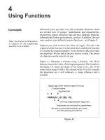
Figure 1
.1
/UC5ICor.J
/
C(llT1J'11i:jnd
~Ine.
Co'ordlna+ e
Readout
/
Move your cursor across
the screen to the right
of
the
drawing area.
If
the nUll
-hers in the coordinate
readout are under 100, you
have opened an ilnperial
file.
If
they are over 500,
youhave openedinmetric.
Once you have entered the Drawing Editor,
AutoCAD establishes a default working
environment. There may also be some 'floating
palettes'
on
the screen (Sheet Sets, Tool Palettes).
Click on the X at the top
right corner
of
each palette
to clear these
off
your
screen so it looks like
Figure 1.1. Make sure your
workspace is AutoCAD
Classic (Releases 2007 and
2008).
Starting a
Drawing
in
Metric
or
Imperial
Changing Imperial
and
Metric
It
is best to start
off
immediately with the units that
you want to use.
If
you have started
in
the wrong
units, open a new file with acad.dwt (imperial)
or
acadiso.dwt (metric).
The command
STARTUP
can also be used. This will
prompt for either imperial or metric without the other
options.
'·~PTWT;;P'I;;·~'·····_·-'"·~~·
.
'~~'.~.
~.
~Sheet5et$
tijatad
-Named
Plot
Styles dwt
g;acad.dwt
liIacadISO
Named
Plot Styles,dwt
lliacadiso.dwt
til
ANSI
A (portraitl-Color Depe.,.
Command:
STARTUP
Enter
new
value
for
startup
<0>:1
C
om rnand
:
NEW
Introductory Geometry and Setting Up 1
More free ebooks :
Pickeither imperial or metric from the dialog box.
If
you
don't
start in the rightunits,
your
dimensioning, area, and volume calculations will be difficult.
Figure
1.2
The UNITS
Command
If you pick a point on the graphics
screen,
you start to
draw
a rectangle,
Pick
another
point
and it will
disappear.
In
AutoCAD it is suggestedthat youdraw everything at full scale
or
1:
1 scale, andplot
the drawing at the required scale factor later.
Once you have chosen your deired units
from the startup menu, you then use the
UNITS
command to set your readout
only.The type
of
units chosen detennines
how AutoCAD interprets coordinate and
angle command entries. The 'Insertion
scale' area indicates againyourbaseunits.
AutoCAD offers various types
of
units
of
measure for use on
your
drawings. Before
setting up the parameters
of
the drawing,
first set
up
the units so thatthe readout dis-
plays the required units. Decimal mode
may be usedfor Inetric units as well as for
imperial units.
Be
sure you have set up
your
file correctlyfortheunits thatyoure-
qUIre.
+x
-y
+y
-x
Figure
1.40
Starting to
Draw
AutoCAD uses Cartesian coordinates for
point entry. The points are set around a de-
termined origin atXO,
YO,
ZOo
In
this caseX
is 21"10". Y is 5'0", and Z is 0.0000. All
points to the right
of
0,0 have a positiveX
value; all points to the left have a negative
X All points above 0,0 have a positive Y
value; all points
below
have negative
Y.
Moving the cursor around the screen you
will notice that the 0,0 position defaults to
the bottom left corner
of
your
screen. See
Figures 1.4a and Figure
lAb.
The decimal unit type will display one
millimeterfor oneunit. Specify the number
of
decimal places for your readout using preci-
sion, as in Figure
1.2.
The engineering and architectural modes as-
sume that one drawing unit equals one inch.
Again
set your precision, as shown in Figure
1.3. Fractional
and
scientific settings will
give a readout in those specific units. Again,
the
UNITS
cOlnmand only sets the readout.
If
you are setting your
UNITS
in inches, but your
'Insertion scale' is luillimeters, then you will
have problems later.
The
UNITS
command
can
be
accessed either Figure 1.3
through the
command
line or through the
UNITS
dialog box from the
Fonnat
pull-down
menu
at the top
of
your screen.
i
Ilf you press the space
bar
before
entering any other
command
just
as
you open the file, the system
might
offer you the
'HELP'
files. To get the
'HELP'
files
off
screen, click
on
the X
at
the
top
right.
Figure
1.4b
2 CHAPTER
ONE
More free ebooks :
(:hoosing the
Origin
The origin
or
0,0 should be the most easily accessible point on the design.
If
a large
percentage
of
the dimensions on a drawing stemfrom one point, it shouldbe made the
origin. The coordinate readout on the bottom
of
the screen
is
there to help you fmd
your position. The placement
of
the origin is important to establish a base for your
readouts.
It
will be more important later when merging files.
To move 0,0 from the bottom
of
the screen use the
PAN
command,
as
in Figure 1.5.
y
Figure 1.5
Often you can press down on the roller ball
of
your mouse to get
PAN.
The command
line equivalent is
PAN
or
just
P.
Command:
PAN
(drag
the
icon
across
the
screen
to
where
you
want
it)
In architectural drawings the origin
is
often atthe bottomleftcomer, as
in
Figure 1.6.
upper right 35',30'
0,0
*===::::::=a_-=!.I
-2',-2'
lower left
Figure
1.6
0,0
-5',-5'
lower left
upper right 50',45'
1
42'
1
In mechanical applications it
is
often in the center, as in Figure
1.7_
upper right 2,2
upper right 10,20
-2,-2
lower left
Figure 1.7
1.2
-10,-20
lower left
16
Introductory Geometry and Setting Up 3
More free ebooks :
Using
PAN
to
get Started
I
i
In
the
command
examples, the bold
type
is
the
user
entry
or
response.
The easiestway to start a file is
by
using 0,0 as the startingpoint. Use
PAN
to move the
origin or 0,0 to the center
of
the screen. Then draw your first object using 0,0 as the
fIrst point.
The
PAN
command is as follows:
The command line equivalent is
PAN
or
P.
Once centered, draw a circle, then use ZOOM All to fit it to your screen, as in Figure
1.8. The same can be done using
LINE.
The
CIRCLE
command is explained further on
page 11, but the commands below will show how it works.
PAN
Figure
1.8
y
~x
CIRCLE
ZOOM
ALL
The LIMITS
Command
4
CHAPTER
ONE
Command:PAN
(move
your
0,0
to
the
center
of
the
screen
as
in
Figure
1.5)
Command:CIRCLE
Specify
center
point
for
circle
or
[3P/2P/Ttr
(tan
tan
radius)]
:0,0
Specify
radius
of
circle
or
[Diameter]<1'-O">:5
Command:
ZOOM
Specify
corner
of
window,
enter
a
scale
factor
(nX
or
nXP),
or
[All/Center/Dynamic/Extents/Previous/Scale
/Window/ObjectJ<real
time>:ALL
LIMITS
sets a flexible general size for yourdrawing.
LIMITS
sets the size
of
your screen
and the area covered
by
the screen grid. Unlike drawing on paper, you can change the
LIMITS
size at any time.
It
simply gives you a place to start and helps provide a visual
size that you can identify with.
The command line equivalent is
LIMITS.
Setting
LIMITS
does not limit yourmodel; it merely lets you determine how big the fin-
ished product might be. You can reset the
LIMITS
at any time simply by picking new
points on the screen.
ZOOM All allows you to view the size you have chosen.
More free ebooks :
Open
acad.dwt.
Change
your
UNITS to Architectural
and
draw
in a line
ZOOM
All
to
see
it
on
the
screE"n.
Use LIMiTS;
GRID
and
SNAP
to
set
up
a
drawing
environment.
Draw
a line
or
circle the size
of
your
part, then use
ZOOM
All.
Set
up
your
LIMITS,
GRID
and
SNAP
if
they
might
be useful.
Draw
a line
or
circle the size
of
your
part, then
ZOOM
All.
A Sample
Set
Up
A house that is 40' x 36'.
The following commands will center the frrst line on your screen without
LIMITS.
Command:
LINE
LINE
Specify
first
point:O,O
Specify
next
point
or
[Undo]
:40'
,0
Specify
next
point
or
[Undo]:~
Command:
ZOOM
Specify
corner
of
window,
enter
a
scale
factor
(nX
or
nXP),
or
[All/Center/Dynamic/Extents/Previous/Scale
/Window/Object]<real
time>:ALL
You can also draw this using LIMITS.
Command:
LIMITS
Reset
Model
space
limits
Specify
lower
left
corner
or
[ON
/ OFF]
<0'-0",0'-0">:-5'
,-5'
Specify
upper
right
corner
<12.0000,9.0000>:45'
,40'
Command:
ZOOM
Specify
corner
of
window,
enter
/ObjectJ<real
time>:ALL
Cornmand:LINE
LINE
Specify
first
point:O,O
Specify
next
point
or
[Undo]
:40'
,0
Specify
next
point
or
[Undo]:~
Setting
LIMITS,
SNAP
and
GRID
LIMITS
sets an overall size for your design.
SNAP
sets an increment that the cursor will
move by.
GRID
sets a visual aid to help you place objects, and is often set to twice the
SNAP
value. The grid will extend over the area given
by
the
LIMITS
command.
To find
GRID
and
SNAP:
The command line equivalent is
SNAP
or
GRI
D.
Command:
LIMITS
Reset
Model
space
limits
Specify
lower
left
corner
or
[ON/OFF]<0.OOOO,O.OOOO>:-S,-40
Specify
upper
right
corner<12.0000,9.0000>:240,180
Command:
ZOOM
Specify
corner
Extents/Left/Previous/Scale/Window]<real
time>:ALL
Command: SNAP
Specify
snap
spacing
(X)
or
[ON/OFF/Aspect/Rotate/Style/Type]<1.0000>:5
Corn 'Tland:
GRID
Specify
grid
spacing
or
[ON/OFF/Snap/Aspect]<O>:10
Introductory
Geometry
and
Setting
Up
5
More free ebooks :
Entry of Points
Coordinate Entry
using Absolute,
Relative,
and
Polar Values
The DYNamic function
is
very useful
but confusing at first. Turn it
off
for
coordinate entry
by
clicking the icon.
DYNamic
off
DYNamic on
6
CHAPTER
ONE
All parts
of
geometry are entered
by
means
of
points. Lines have two points each.
circles have a
centerpoint
and
a
point
determiningthe radius. Arcs have a centerpoint,
a radius point, a start point,
and
an
end
point.
There
are three ways
of
entering points:
by
coordinates:
absolute
values,
relative
values,
or
polar
values
picking
them
on
the
screen,
with
or
without
SNAP
or
DYNamic
relative
to
existing
geometry
In
this chapter
we
will
look
only
at
the first
two
methods
of
point
entry.
The
LINE
com-
mand
will
be
used
to illustrate coordinate entries.
The
LINE
Command
Find
LINE
as follows:
The
command
line
equivalent
is
LINE
or
the
command
alias
L.
Co~~and:LlNE
or
L
To
create a
LINE,
you
will
need
to
know
where
it starts
and
where
it
ends.
Pick
two
or
more points on the
screen
or
enter
the coordinates.
Tenninate
the
command
by
press-
ing the Enter
key
(.J) .
The coordinates
of
an item, the X
and
Yvalues,
can
be entered either relative
to
the
origin (the absolute value
of
the line)
or
relative to the last
point
entered (the
incremental value).
Absolute Value Entries
In
this method, the origin
of
the
model
or
drawing
does
not
change: the objects are
placed
relative to the origin.
To
enter
the absolute value
of
an
item, type
in
theX value,
then
the Y value, separated
by
a comma.
You
will need to enter two sets
of
values to
draw
a line. Press the
enter
key
-I
to signal the
end
of
the coordinate entry and
you
should get the line
shown
in
Figure
1.9.
Command:LlNE
Specify
first
point:O,O
Specify
next
point
or
[Undo]
:4,0
Figure
1.9
This will
draw
a line from the absolute position
of
0,0 to the absolute position
of
4,0.
More free ebooks :
Relative Value Entries
To enter an incremental or relative value, type the @ symbol (Shift-2) before the
number.
@ means
'from
the last point.'
Command:LINE
Specify
first
point:2,3
Specify
next
point
or
[Undo]
:@4,0
This will draw a line from the absoluteposition
of2,3
to a position4 units in positiveX
from this point.
Try these two examples:
Absolute
Comrnand:LINE
Specify
first
point:O,O
Specify
next
point
or[Undo]
:4,0
Specify
next
point
or[Undo]
:4,4
Specify
next
point
or
[Undo]
:0,4
Specify
next
point
or
[Undo]
:0,0
Specify
next
point
or
[Undo]:~
D
Figure 1.10
Relative
Comrnand:LINE
Specify
first
point:5,5
Specify
next
[Undo]
:@4,O
Specify
next
[Undo]
:@O,4
Specify
next
[Undo]
:@-4,O
Specify
next
[Undo]
:@0,-4
Specify
next
[Undo]
:~
The exampleon the left in Figure 1.10 is a four-unit square starting at0,0. Theexample
on the right is a four-unit square starting at 5,5. Both squares are createdrelative to the
origin, 0,0.
To draw a line from point 5,6 to point 8.3,6 use either
of
the following:
Absolute
Command:
LINE
Specify
first
point:5,6
Specify
next
point
or[Undo]
:8.3,6
Relative
Command:
LINE
Specify
first
point:5,6
Specify
next[Undo]
:@3.3,0
In choosing between the absolute and the incremental method, the deciding factor is
what you know.
If
you know that the final point is going to be 8.3,6, use the absolute
value.
If
youknow that the line is going to
be
3.3 units
inpositiveXfrom
the last point,
then enter the incremental coordinates. AutoCAD will do the calculations.
Introductory Geometry and
Setting
Up
7
More free ebooks :
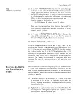
Polar Value Entries
Polar coordinates allow you to enter an item, relative to the last item, at a specified
length and angle. Angles are normally calculated counterclockwise from the positive
X direction, as shown in Figure 1.11.
Command: LINE
Specify
first
point:3,4
Specify
next
point
or
[Undo]
:@4<45
~@4<45
3,4
</,, 4 J45
0
Figure 1.11
90
180
+-+ '-~-
270
o
Where: @
4
<
45
relative to the last point
the length
of
the line
angle
the angle that the line
will
be
drawn at; all angles are calculated
counterclockwise
@1<210
Try this example:
Command: LINE
Specify
first
point:6,O
Next
point:@2<O
Next
point:@3<90
Next
point:@2<O
Next
point:@1<270
Next
point:@2<O
Next
point:@2<90
Next
point:@6<150
Next
point:@1<210
Next
point:C
(for
close)
Close
6,0
@2<0
@6<150
@2<90
@2<0
@1<270
@
@2<O
3<90
Coordinate Entry
using
SNAP,
ORTHO,POLAR,
and
DYNAMIC
8
CHAPTER
ONE
As noted above, angles are calculated counter- Figure 1.12
clockwise from the furthest point in positive X
Functions that can help you enter your drawing information are found at the bottom
of
your screen. Thelefthand button onthemouse will enter apointeverytime youpress it
while in a draw command.
Yau
can make your digitizing
or
picking
of
points much
easier and more accurate
by
using functions such as
SNAP,
POLAR
and
ORTHO.
The
function bar is shown
in
Figure 1.13.
Figure 1.13
More free ebooks :