recommendations for design of slab-column connections in monolithic reinforced concrete structures
Bạn đang xem bản rút gọn của tài liệu. Xem và tải ngay bản đầy đủ của tài liệu tại đây (527.81 KB, 26 trang )
ACI
352.1R-89
(Reapproved 1997)
Recommendations for Desig
n of Slab-Column C
onnections in
Monolithic Reinforced Concrete Structures
Reported by ACI-ASCE Committee 352
James K. Wight
Chairman
James R.
Cagley*
Marvin E.
Criswell*
Ahmad
J.
Durrani
Mohammad R. Ehsani
Luis E. Garcia
Neil M. Hawkins*
Norman W. Hanson
Secretary
Milind R. Joglekar
Cary
S.
Kopczynski*
Michael E.
Kreger*
Roberto T. Leon*
Donald F. Meinheit
Jack P. Moehle, Sub-Committee Chairman for Preparation
of the Slab-Column Recommendations
Robert Park* Gene R. Stevens*
Clarkson
W.
Pinkham
Donald R. Strand
Mehdi Saiidi*
S. M. Uzumeri
Charles F.
Scribner
Sudhakar P. Verma
Mustafa Seckin
Loring
A.
Wyllie,
Jr.
Liande Zhang
Recommendations are given for determining proportions and
details
of monolithic, reinforced concrete slab-column connections.
Included are recommendations regarding appropriate uses of
slab-
column connections in structures resisting gravity and lateral
forces,
procedures for
determination
of connection design forces, proce-
dures for determination of connection strength, and reinforcement
details to insure adequate strength, ductility, and structural integrity.
The recommendations are based on a review of currently available
information. A commentary is provided to amplify the recommen-
dations and identify available reference material. Design
examples
il-
lustrate application of the recommendations. (Design recommenda-
tions are set in standard
type.
Commentary is set in italics.)
Keywords: anchorage (structural); beams (supports); collapse; columns (sup
ports); concrete slabs; connections; earthquake-resistant structures; joints
(junctions); lateral pressure: loads (forces); reinforced concrete; reinforcing
steels; shear strength; stresses; structural design; structures.
CONTENTS
Chapter 1 -Scope,
p.
1
Chapter 2-Definitions and classifications, p. 2
2.l-Definitions
2.2-Classifications
Chapter 3-Design considerations,
p.
5
3.l-Connection performance
3.2-Types of actions on the
connection
3.3-Determination
of connection forces
ACI
Committee Reports, Guides, Standard Practices, and
Commentaries are intended for guidance in designing, plan-
ning, executing, or inspecting construction and
in preparing
specifications. Reference to these documents shall not be made
in the Project Documents. If items found in these documents
are desired to be part of the Project Documents they should
be phrased in mandatory language and incorporated into the
Project Documents.
Chapter
4-Methods
of analysis for
determination of connection strength,
p.
6
4.1-General principles and recommendations
4.2-Connections without beams
4.3-Connections
with transverse beams
4.4-Effect of openings
4.5-Strength
of the joint
Chapter 5-Reinforcement recommendations,
p.
10
5.l-Slab reinforcement for moment transfer
5.2-Recommendations for the joint
5.3-Structural
integrity reinforcement
5.4-Anchorage
of reinforcement
Chapter 6-References,
p.
16
6.l-Recommended references
6.2-Cited references
Examples,
p.
17
Notation,
p.
22
CHAPTER 1-SCOPE
These recommendations are for the determination of
connection proportions and details that are intended to
provide for adequate performance of the connection of
cast-in-place reinforced concrete slab-column connec-
tions. The recommendations are written to satisfy ser-
viceability, strength, and ductility requirements related
to the intended functions of the connection.
*Members of the slab-column subcommittee.
Copyright
0
1988, American Concrete Institute.
All rights reserved including rights of reproduction and use in any
form
of
by any means, including the making of copies by any photo process, or by any
electronic or mechanical device, printed, written, or
oral,
or
recording for sound
or visual reproduction or for use in any knowledge or retrieval system or de-
vice, unless permission in writing is obtained from the copyright
proprietors.
352.1
R-1
352.1 R-2
MANUAL OF CONCRETE PRACTICE
Design of the connection between a slab and its sup-
porting member requires consideration of both the joint
(the volume common to the slab and the supporting
element)
and
the
portion
of the slab or slab and beams
immediately adjacent to the joint. No reported cases of
joint distress have been identified by the Committee.
However, several connection failures associated with
inadequate performance of the slab adjacent to the
joint have been reported.
‘J
Many of these have oc-
curred during construction when young concrete re-
ceived loads from more than one floor as a conse-
quence of shoring and
reshoring.8-‘0
The disastrous
consequences of some failures, including total collapse
of the structure, emphasize the importance of the de-
sign of the connection. It is the objective of these rec-
ommendations to alert the designer to those aspects of
behavior that should be considered in design of the
connection and to suggest design procedures that
will
lead to adequate connection performance.
Previous reports
5,11
and codes (ACI 318) have sum-
marized available information and presented some de-
sign recommendations. The present recommendations
are based on data presented in those earlier reports and
more recent data.
The recommendations are intended to serve as a
guide to practice.
These recommendations apply only to slab-column
connections in monolithic concrete structures, with or
without drop panels or column capitals, without slab
shear reinforcement, without prestressed reinforce-
ment, and using normal weight or lightweight concrete
having design compression strength assumed not to ex-
ceed
6000
psi. Construction that combines slab-column
and beam-column framing in orthogonal directions at
individual connections is included, but these recom-
mendations are limited to problems related to the
transfer of loads in the direction perpendicular to the
beam axis. The provisions are limited to connections
for which severe inelastic load reversals are not antici-
pated. The recommendations do not apply to multi-
story slab-column construction in regions of high seis-
mic risk in which the slab connection is a part of the
primary lateral load resisting system. Slab-column
framing is inappropriate for such applications.
These recommendations are limited to slab-column
connections of cast-in-place reinforced concrete floor
construction, including ribbed floor slab construction
12
and slab-column connections with transverse beams.
Recommendations are made elsewhere (ACI
352R)
for
connections in which framing is predominantly by ac-
tion between beams and columns.
The recommendations do not consider connections
with slab shear reinforcement, slab-wall connections,
precast or prestressed connections, or slabs on grade.
The Committee is continuing study of these aspects of
connection design. Relevant information on these sub-
jects can be found in the literature. (See References 5,
11, and 13 through 18 for slab shear reinforcement,
References 19 and 20 for slab-wall connections, and
ACI
423.3R,
and References 21 through 26 for
pre-
stressed connections.) Although structures having con-
crete compressive strength exceeding
6000
psi are within
the realm of this document, the recommendations limit
the assumed maximum value of compressive strength to
6000 psi.
Slab-column framing is generally inadequate
as
the
primary lateral load resisting system of multistory
buildings located in regions of high seismic risk (such as
Zones 3 and 4 as defined in ANSI A.58.1 and UBC)
because of problems associated with excessive lateral
drift and inadequate shear and moment transfer capac-
ity at the connection. In regions of high seismic risk, if
designed according to provisions of these recommen-
dations, slab-column framing may be acceptable in
low-
rise construction and multistory construction in which
lateral loads are carried by a stiffer lateral load resist-
ing system. In regions of low and moderate seismic risk
(such as Zones I and 2 as defined in ANSI A.58.1 and
UBC),
slab-column frames may be adequate as the pri-
mary lateral load resisting system, provided the con-
nection design recommendations in this document are
followed.
CHAPTER 2-DEFINITIONS AND
CLASSIFICATIONS
2.1 -Definitions
Joint-The part of the column within the depth of
the slab including drop panel and having plan dimen-
sions equal to those of the column at the intersection
between the column and the bottom surface of the slab
or drop panel.
Connection-The joint plus the region of the slab
and beams adjacent to the joint.
Column-A cast-in-place vertical supporting ele-
ment, including column capital if provided, with or
without construction joints, designed to resist forces
from the slab at the connection, and having a ratio of
long to short cross-sectional dimensions not exceeding
four.
Column capital-A flared portion of the column be-
low the slab, cast at the same time as the slab, and hav-
ing effective plan dimensions assumed equal to the
smaller of the actual dimensions and the part of the
capital lying within the largest right circular cone or
pyramid with a
90-deg
vertex that can be included
within the outlines of the supporting column.
Drop panel-A thickened portion of the slab around
the column having thickness not less than one-quarter
of the surrounding slab thickness and extending from
the column centerline in each principal direction a dis-
tance not less than one-sixth of the center-to-center
span between columns.
Shear capital-A thickened portion of the slab
around the column not satisfying plan dimension re-
quirements for drop panels.
Slab critical section-A cross section of the slab near
the column, having depth d perpendicular to the slab
and extending around the column (including capital). A
critical section should be considered around the col-
umn so that its perimeter
b, is a minimum, but it need
DESIGN OF SLAB-COLUMN CONNECTIONS
352.1 R-3
not approach closer than the lines located d/2 from the
column face and parallel to the column boundaries.
Alternate critical sections should be investigated at
other sections that might result in reduced shear
strength. For the purpose of defining the slab critical
section, a support of circular cross section may be re-
placed by a square support having an equal cross-sec-
tional area.
Direction of moment-Defined to be parallel to the
flexural
reinforcement placed to resist that moment. In
connection design and analysis, moments may be ideal-
ized as acting about two orthogonal axes, in which case
orthogonal directions are defined for the moments.
Transfer moment-The portion of the slab total mo-
ment transferred to the supporting element at a con-
nection. The transfer moment is identical in meaning to
the unbalanced moment as defined in
ACI
318.
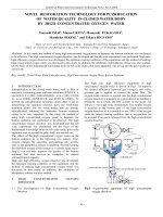
Performance of a connection can be affected by be-
havior of the joint (including slip of reinforcement
embedded in the joint) and by the region of the slab or
slab and beams surrounding the joint. In general, the
region of slab that directly affects behavior of the con-
nection extends from the joint face not more than ap-
proximately twice the development length of the largest
slab bars or four slab thicknesses, whichever is
greater.” The joint definition is illustrated in Fig. 2. 1.
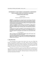
The slab critical section, used for slab strength deter-
mination, is the same as that specified in ACI 318, al-
though the definition has been modified to clarify that
slab critical sections for rectangular supports may be
assumed to have a rectangular shape. The slab critical
sections for several support geometries are shown in
Fig. 2.2. Punching shear strengths for circular columns
have been observed’” to exceed the punching shear
strengths for square columns having the same
cross-
sectional area. Thus, it is conservative and may be an-
alytically simpler to represent circular columns by
square columns having the same cross-sectional area
[Fig.
2.2(c)].
Two critical sections are defined for con-
nections with drop panels or shear capitals because
failure may occur either through the thickened portion
of the slab near the column or through the slab outside
the drop panel or shear capital [Fig. 2.2(d)].
Fig. 2.3 illustrates the limitation on the aspect ratio
of the column cross-sectional dimensions. As the as-
pect ratio becomes elongated, behavior deviates from
that which is assumed in this
report.20
In such in-
stances, the connection between the supporting mem-
ber and the slab should be designed as a slab-wall con-
nection. No recommendations for such connections are
made in this report. Information is available in the
lit-
erature.‘g~20
The direction of moment is parallel to slab reinforce-
ment placed to resist that moment. For example, in a
one-way slab (Fig. 2.4), the direction of moment is
parallel to the span of the slab. Using vector notation,
the moment vector [Fig.
2.5(c)]
is perpendicular to the
moment direction.
2.2-Classifications
Connections are classified according to geometry in
Section
2.2.1
and according to anticipated performance
in Section 2.2.2.
2.2.1 A slab-column connection is an exterior con-
nection if the distance from any discontinuous edge to
the nearest support face is less than four slab thick-
nesses. An edge connection is an exterior connection
for which a discontinuous edge is located adjacent to
one support face only. A corner connection is an exte-
rior connection for which discontinuous edges are lo-
cated adjacent to two support faces. A vertical slab
opening located closer than four slab thicknesses to the
support face should be classified as a discontinuous
edge if radial lines projecting from the centroid of the
support area to the boundaries of the opening enclose a
length of the slab critical section that exceeds the
adja-
drop
panel
or
shear capitol
slab
h
1
y
b
Elevation
Note:
The joint is indicated by shading
m
Fig.
2.1-Joint
in typical slab-column connections
A
ia%
A
V
Elevation
352.1 R-4
MANUAL OF CONCRETE PRACTICE
I
(a)
d
T
(c)
(b)
&!-
shear capital,
slab
critical
sections
column
(d)
I
Discontinuous
slab edge
r
1
+greater
than
+
+
d
Note: For exterior connections, the slab critical section
should extend to the slab edge as shown in (e)
if such extension will reduce the critical section perimeter.
Otherwise, the slab critical section is as shown in (f)
Fig. 2.2-Examples of slab critical sections
C
Note:
The
recommendations apply
only if
c,
/
c2<
4
c
Direction
of Moment
-
Fig. 2.3-Limitation on column aspect ratio
cent
support
dimension. A connection not defined as an
exterior connection is considered to be an interior con-
nection.
Openings or slab edges located close to the support
interrupt the shear flow in the slab, induce moment
transfer to supports, reduce anchorage lengths, and re-
duce the effective joint confinement. The distance of
four times the slab thickness is based on considerations
related to strength of the slab near the support.
11
Sev-
eral examples of exterior connections are in Fig. 2.5.
Where openings are located closer than four slab
thicknesses, the connection may behave as an exterior
connection, depending on the size and proximity of the
opening. To gage approximately the effect of the open-
ing, radial lines are drawn from the centroid of the
support area to the boundaries of the opening
[Fig.
2.5(e)]. If the length of the slab critical section enclosed
within the radial lines exceeds the adjacent support di-
mension, the connection is classified as an exterior
connection. In the preceding, if there are no shear cap-
itals, a support should be interpreted as being the col-
umn plus column capital if present. If there are shear
capitals, the effect of the opening should first be
checked considering the column to act as the support,
and secondly, considering the shear capital to act as the
352.1 R-5
Plan
Fig. 2.4-Moment direction for one-way slab
support. For the purpose of classifying a connection as
interior or exterior, the effect of openings on the criti-
cal section around a drop panel need not be consid-
ered.
Where distances to openings and free edges exceed
the aforementioned requirements, the connection may
be defined as being interior. In such cases, the diameter
of the longitudinal bars should be iimited so that ade-
quate development is available between the column and
the opening or edge. Recommendations given
elsewhere” suggest that bars should be selected so that
the development length is less than half the distance
from the column face to the edge or opening.
2.2.2 A connection is classified as either Type 1 or
Type 2 depending on the loading conditions of the con-
nection as follows:
(a) Type 1: A connection between elements that are
designed to satisfy
ACI
318 strength and serviceability
requirements and that are not expected to undergo de-
formations into the inelastic range during the service
life.
(b)
Type 2: A connection between elements that are
designed to satisfy
ACI
318 strength and serviceability
requirements and that are required to possess sustained
strength under moderate deformations into the inelas-
tic range, including but not limited to connections sub-
jected to load reversals.
The design recommendations for connections are de-
pendent on the deformations implied for the design
loading conditions. A Type I connection is any con-
nection in a structure designed to resist gravity and
normal wind loads without deformations into the in-
elastic range for expected loads. Some local yielding of
slab reinforcement may be acceptable for Type I con-
nections. Slabs designed by conventional yield-line
methods may be included in this category, except if re-
quired to resist loads as described for Type 2
connec-
(a) Edge Connectton
(b) Corner Connection
unbalanced
moment
vector
(c) Edge Connection with
Transverse
(Spandrel) Beom
(d) Edge Connection with
Short Slab Overhang
radial
line
to boundary of
opening
a
=
length
of crltlcal section
within radial lines
b
=
dear distance between
support
and opening
c
= column dimension
Note: Connection considered exterior
if
>
c
and b < 4h
(e)
Connection with
Significant
Opanlng
Fig.
2.5-Examples
of exterior connections
tions. A Type 2 connection is a connection between
members that may be required to absorb or dissipate
moderate amounts of energy by deformations into the
inelastic range. Typical examples of Type 2 connec-
tions are those in structures designed to resist earth-
quakes or very high winds. In structures subjected to
very high winds or seismic loads, a
slab-column
con-
nection that is rigidly connected to the primary
lateral
load resisting system should be classified as a Type 2
connection even though it may not be considered dur-
ing design as a part of that primary lateral load resist-
ing system. As noted in Chapter 1, these recommenda-
tions do not apply to multistory frames in regions of
high seismic risk in which slab-column framing is con-
sidered as part of the primary lateral load resisting sys-
tem.
CHAPTER 3-DESIGN CONSIDERATIONS
3.1-Connection performance
The connection should be proportioned for service-
ability, strength, and ductility to resist the actions and
forces specified in this chapter.
3.2-Types of actions on the connection
3.2.1
The design should account for simultaneous ef-
fects of axial forces, shears, bending moments, and
torsion applied to the connection as a consequence of
352.1 R-6
MANUAL OF CONCRETE PRACTICE
external loads, creep, shrinkage, temperature, and
foundation movements. Loads occurring during con-
struction and during the service life should be consid-
ered.
The connection should be designed for
the forces due
to applied external loads and due to time-dependent
and temperature effects where they are significant. Ef-
fects of construction loads and early concrete strengths
are of particular importance for slabs without beams,
as demonstrated by several catastrophic failures during
construction.‘-4
Effects of heavy construction equip-
ment and of shoring and
reshorin~27*28
should be con-
sidered. Effects of simultaneous bidirectional moment
transfer should be considered in design of the connec-
tion, except wind or seismic lateral loads generally are
not considered to act simultaneously along both axes of
the structure in design.
3.2.2 Moment transfer about any principal axis
should be included in evaluating connection resistance
if the ratio between the factored transfer moment and
factored slab shear at the slab critical section exceeds
0.2d,
where d is the slab effective depth. The moment
should be taken at the geometric centroid of the slab
critical section defined in Section 2.1. Where biaxial
moments are transferred to the support, the
0.2d
limi-
tation can be applied independently about both princi-
pal axes of the connection.
Moment transfer at a connection can reduce the
shear strength of a slab-column connection. However,
the strength reduction for eccentricity less than
0.2d
is
within the experimental scatter for nominally identical
connections transferring shear only.”
3.3-Determination of connection forces
3.3.1
Forces on the connection may be determined by
any method satisfying requirements of equilibrium and
geometric compatibility for the structure. Time-depen-
dent effects should be evaluated.
3.3.2 For normal gravity loads, the recommenda-
tions of Section 3.3.1 may be satisfied using the Direct
Design Method or the Equivalent Frame Method of
ACI
318. For uniformly loaded slabs, slab shears at the
connection may be determined for loads within a trib-
utary area bounded by panel centerlines; slab shears at
first interior supports should not be taken less than 1.2
times the tributary area values unless a compatibility
analysis shows lower values are appropriate.
The design should account for the worst combina-
tions of actions at the connection. Analysis for connec-
tion forces should consider at least (a) loads producing
the maximum slab shear on the slab critical section, and
(b) loads producing the maximum moment transfer at
the slab critical section.
Factored slab shear at the connection can be deter-
mined by several procedures, including yield line and
strip design
methods’3n29
and the equivalent frame
method. However, in typical designs, simpler proce-
dures such as the use of tributary areas are acceptable.
The designer is cautioned that the shear at first interior
supports is likely to be higher (by as much as 20 per-
cent) than the tributary area
Shea&**”
because of con-
tinuity effects.
3.3.3 For lateral loads, effects of cracking,
compati-
bility, and vertical loads acting through lateral dis-
placements (P-delta effects) should be considered.
Cracking in the connection has been showrP4 to re-
duce connection lateral-load stiffness to a value
well
below the stiffness calculated by the elastic
theory.32~35
The reduction
in
stiffnes
can result
in lateral drift ex-
ceeding that anticipated by a conventional elastic anal-
ysis. Effects of gravity loads acting through lateral dis-
placements (P-delta effects) are consequently amplified
and may play an important role in behavior and stabil-
ity of slab-column frames. Methods of estimating re-
duced lateral-load stiffness are discussed in References
32, 33, and ACI
318R.
CHAPTER 4-METHODS OF ANALYSIS FOR
DETERMINATION OF CONNECTION STRENGTH
4.1 -General principles and recommendations
Connection strength may be determined by any
method that satisfies the requirements of equilibrium
and geometric compatibility and that considers the lim-
iting strengths of the slab, the column, and the joint. In
lieu of a general analysis, strength of the slab included
in the connection may be determined according to the
procedures given in Sections 4.2, 4.3, and 4.4, and
strength of the joint may be determined according to
Section 4.5.
Methods of computing strength of the slab in shear
and moment transfer have received considerable atten-
tion in literature in recent years. Available methods in-
clude applications of yield line theory, elastic plate the-
ory, beam analogies, truss models, and
others.‘n3@’
The
explicit procedures given in Sections 4.2, 4.3, and 4.4
provide acceptable estimates of connection strength
with a reasonable computational effort. It is noted that
moment transfer strength of a connection may be lim-
ited by the sum of the strengths of columns above and
below the joint;
hence, connection strength should
not
be
assumed to exceed this limiting value.
4.2-Connections without beams
The connection should be proportioned to satisfy
Sections 4.2.1 and 4.2.2.
4.2.1
Shear
4.2.1.1 Connections transferring shear-Shear
strength
I’,
in the absence of moment transfer is given
by
V,
=
$I
I’,,
where
V,
=
C,V,
(4-l)
in which
$I
= 0.85,
V,
= the nominal shear strength,
I’,
= basic shear strength carried by concrete, and
C,
is
the product of all appropriate modification factors
given in Table 4.1 and is taken equal to 1.0 if none of
the modification factors of Table 4.1 are applicable
Table
4.1
-
Modification factors for basic shear
strength
DESIGN
OF
SLAB-COLUMN CONNECTIONS
in which
P,
= ratio of long to short cross-sectional di-
mensions of the supporting column, A
cs
= cross-sec-
tional area of the slab critical section =
b,d,
andyi
=
Condition
concrete compressive strength in units of psi and not to
exceed 6000 psi.
All-lightweight concrete
Eq. (4-l) defines shear strength in the absence of
Sand-lightweight concrete
moment transfer. The presence of moment may result
Flexural
yielding anticipated
in decreased shear strength. Therefore, the designer is
in slab, including all Type 2
connections
cautioned when computing the required connection
moment strength to consider effects of pattern loads,
lateral loads, construction loads, and possible acciden-
tal loads.
20 <
b,/d
<
40
0.75
b./d
> 40
0.5
Eq.
(4-l)
is based on a similar equation for two-way
shear strength as presented in the
ACI
318. However,
modification factors not included in ACI
318
are in-
cluded in these recommendations. The basic shear
strength should be multiplied by each of the
applicable
modification factors in Table 4.1 to arrive at the nom-
inal shear strength
V
n
.
The
modification
factors reflect
how each variable individually affects shear strength.
There is little experimental information to show that
the effects are cumulative. The Committee recommen-
dation is intended to be conservative.
The maximum
value
of
4fl&,
for the basic shear
strength given in Eq. (4-2) exceeds the nominal strength
of
2Kbd,,
used for beams
largely
because of the
geometric confinement afforded to the slab shear fail-
ure surface. As the supporting column cross section be-
comes elongated, the confinement due to lateral
compression along the long face is diminished. The
term
&
in Eq. (4-2) reflects the reduction in strength
due to reduction in lateral confinement. A similar phe-
nomenon arises if the critical section perimeter b,
greatly exceeds the depth
d
of the slab,” as occurs for
the critical section around drop
panels
and shear capi-
tals. The values of the modification factors as a func-
tion of
b,/d
are based subjectively on trends observed
in References 42 and 43. Research on interior connec-
tions with shearhead reinforcemenP shows that the
nominal strength decreases as the distance between the
critical section and the column face increases. An eval-
uation of the data by the Committee indicates that the
reduction may also have been attributable to the in-
crease in the ratio of the critical section dimension to
slab depth.
as a function of the square root of the concrete com-
pressive strength. Some
research’~”
suggests that the re-
lation should be in terms of the cube root of concrete
strength rather than the square root. Thus, it is possi-
ble that shear strength given by Eq. (4-2) is
unconser-
vative for concrete strengths exceeding 6000 psi, the
upper bound of strengths reported in tests of slab-col-
umn connections.
During construction, young and relatively weak con-
crete may need to carry heavy loads. Low concrete
strength has a greater effect on shear strength than
flexural strength. Thus, there is a tendency toward
connection shear failures. In checking resistance to
construction loads that occur before the full design
concrete strength develops, it is important to use the
concrete strength corresponding to the age at which the
load occurs rather than the design strength.
1
yy
=
l-
1+2/3&
4.2.1.2 Connections transferring shear and mo-
ment-Any connection may be designed in accordance
with the recommendations of Section 4.2.1.2(a). Con-
nections satisfying the limitations of Sections 4.2.1.2(b)
or 4.2.1.2(c) may be designed by the procedures listed
in those sections in lieu of the procedure in Section
4.2.1.2(i). All Type 2 connections should satisfy the
recommendation of Section 4.2.1.2(d) in addition to the
other recommendations of this section. All connections
should meet the recommendations of Section 4.2.2.
(a) The fraction of the transfer moment given by
Lightweight aggregate concretes have been
observep
to exhibit lower shear strengths reiative to normal
weight concretes having the same compressive strength.
Connections subjected to widespread
flexural
yield-
ing have been observed42to exhibit shear strengths
lower than those observed for connections failing in
shear prior to
flexural
yielding. Nominal shear strength
for this case is reduced by a factor of 0.75. This provi-
sion should be applied for all Type 2 connections and
for some Type 1 connections. Included in the latter
category are slabs designed by yield-line methods. The
possibility of yield
should
be considered
in flat-slab and
flat-plate floor systems for which
column
layouts are
irregular.
should be considered resisted by shear stresses acting on
the slab critical section. In Eq.
(4-3),
&
is the ratio of
the lengths of the sides of the slab critical section mea-
sured parallel and transverse to the direction of mo-
ment transfer, respectively. The shear stresses due to
moment transfer should be assumed to vary linearly
about the centroid of the slab critical section. The al-
gebraic sum of shear stresses due to direct shear and
moment transfer should not exceed the value of
VJA,.
The basic shear strength given by Eq. (4-2)
is written
(b) Corner connections, and edge connections trans-
ferring moments only perpendicular to the slab edge,
may be assumed to have adequate shear strength if the
factored direct shear transferred to the column does not
exceed 0.75
V,,
with
V,
defined by Eq. (4-l).
(c) Connections supported on columns having a ratio
of long to short cross-sectional dimensions less than or
352.1
R-7
Modification factor
0.75
0.85
0.75
352.1 R-8
MANUAL OF CONCRETE PRACTICE
equal to two may be assumed to have adequate shear
strength to transfer the factored connection shear and
moment if
v0
2
VU
+
a(K,,
+
M&,)/b,
(4-4)
in which b, = perimeter of the slab critical section,
VU
= factored direct shear on the slab critical section, and
A4,,bi
and
Muba
are the factored moments transferred si-
multaneously to the support in the two principal direc-
tions at the geometric centroid of the slab critical sec-
tion. For exterior connections, moments perpendicular
to the slab edge may be taken equal to zero in Eq. (4-4)
if
V,
does not exceed 0.75
V,,
with
I’,
defined by Eq. (4-
1). The value of
LY
should be taken equal to 5 for inte-
rior connections and 3.5 for edge connections.
(d)
For all Type 2 connections, the maximum shear
acting on the connection in conjunction with inelastic
moment transfer should not exceed
0.4~‘~.
Shear strength may be reduced when moments are
transferred simultaneously to the connection. In Sec-
tion 4.2.1.2, several alternate procedures for consider-
ing the effects of moment transfer are recommended.
The most general of the recommended procedures,
which can be applied to connections of any geometry
and loading, is described in Section 4.2.1.2(a). How-
ever, connections can be designed with less computa-
tional effort if they satisfy the loading and geometric
requirements of Section 4.2.1.2(b) or 4.2.1.2(c).
The design method described in Section 4.2.1.2(a) is
identical to the eccentric shear stress model embodied in
ACI
318. It is assumed that shear stresses due to direct
shear on the connection are uniformly distributed on
the slab critical section. In addition, a portion of the
unbalanced moment given by Eq. (4-3) is resisted by a
linear variation of shear stresses on the slab critical sec-
tion. The algebraic sum of shear stresses due to direct
shear and moment transfer should not exceed the value
of
V,/&.
The portion of moment not carried by ec-
centric shear stresses is to be carried by slab
flexural
re-
inforcement according to Section 4.2.2. The method is
described in detail in several references (e.g., ACI
318R,
and Reference 13).
For corner connections, and for edge connections
transferring moment only perpendicular to the slab
edge, a simple computational design procedure is given
in Section 4.2.1.2(b). The procedure is based on
research16
on slab-column edge connections for which
the outside face of the column is flush with the slab
edge. For such connections, moment transfer strength
perpendicular to the slab edge is governed by slab
flex-
ural
reinforcement within an effective transfer width,
and apparently is not influenced significantly by shear
on the connection. Failure apparently occurs when the
connection moment reaches
the
flexural strength of slab
reinforcement, or the connection shear reaches the
shear strength of the slab critical section. In cases where
moments induce yield in slab flexural reinforcement,
shear failure can apparently occur for shear less than
that given by Eq. (4-1) because of loss of in-plane
re-
straint when the
flexural
reinforcement yields. For that
reason, an upper limit equal to three-quarters of the
value given by Eq. (4-1) is recommended. Recommen-
dations for moment transfer reinforcement are given in
Section 4.2.2.
For interior or edge connections having a ratio be-
tween long and short column dimensions less than or
equal to two, effects of moment transfer on shear
strength can be accounted for by proportioning the
connection to satisfy the recommendations of Section
4.2.1.2(c). Eq. (4-4) of that section essentially emu-
lates, in algebraic form, the eccentric shear stress model
described in Section 4.2.1.2(a). The form of Eq. (4-4)
was originally presented by ACI-ASCE Committee
426,
11
which recommended the equation for interior
connections with a value of
(Y
equal to 5.2. The value
of
cy
has been modified to 5.0 for interior connections.
For edge connections transferring moment only paral-
lel to the slab edge, a value of
cy
equal to 3.5
is
appro-
priate. For edge connections also transferring moment
perpendicular to the slab edge, the shear
V,
is
usually
less than
O.l5V,
in which case moments perpendicular
to the slab edge can be ignored in Eq. (4-4). This equa-
tion may be unconservative for connections not satis-
fying the requirement for column cross section aspect
ratio.
The recommendation in Section 4.2.1.2(d) should be
applied to all connections without beams for which in-
elastic moment transfer is anticipated. The recommen-
dation is based on a
revieti’
of data reported in Refer-
ences 33, 34, and 48 through 52, and some previously
unpublished tests, which reveal that lateral
displace-
ment ductility of interior connections without shear re-
inforcement is inversely related to the level of shear on
the connection. Connections having shear exceeding the
recommended value exhibited virtually no lateral dis-
placement ductility under lateral loading. The recom-
mendation of Section 4.2.1.2(d) may be waived if cal-
culations demonstrate that lateral interstory drifts will
not induce yield in the slab system. For multistory con-
struction, stiff lateral load resisting structural systems
comprising several structural walls may be adequate.
4.2.2 Flexure-Slab
flexural
reinforcement should be
provided to carry the moment transferred to the con-
nection in accordance with Section 5.1.1.
4.3-Connections with transverse beams
If a connection has beams transverse to the span of
the slab, shear and moment transfer strength of the
connection may be determined as follows:
4.3.1 Shear strength is the smaller of the following:
(a) Design shear strength limited by beam action with
a critical section extending across the entire slab width
in a plane parallel to the beam and located a distance d
from the face of the beam, where d is the slab effective
depth. Design shear strength for this condition is cal-
culated according to
ACI
318 for beams.
(b) Design shear strength limited by the sum of de-
sign strengths in shear of only the transverse beams.
Design shear strength of the transverse beams at a
dis-
DESIGN OF SLABCOLUMN CONNECTIONS
352.1 R-9
tance
dbwm
from the support face should be computed
considering interaction between shear and torsion,
where
dOCorn
is the beam effective depth.
4.3.2 Moment transfer strength is the smaller of the
following:
(a) Design
flexural
strength of the slab at the face of
the support over a width equal to that of the column
strip.
(b) Sum of the design flexural strength of the slab
and the design torsional strengths of the transverse
beams. Slab design
flexural
strength is computed over
a width equal to that of the support face.
The procedure described is based on concepts of the
beam analogy as presented in Reference 38. The pro-
cedure assumes the shear strength is limited by either
beam action in the slab or by development of shear
strengths of the beams at the side faces of the
connec-
transverse
beam
tion. For connections having substantial transverse
beams, it is unlikely that the beams and slab will de-
velop design shear strengths simultaneously, so shear
strength should be limited to the contribution of the
beams only.
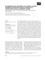
Flexural
strength is limited by development of
a flex-
ural
yield line across the slab column-strip width, in
which case the transverse beams do not reach their de-
sign strengths [Fig. 4.1(a)], or by development of a
yield surface around the connection that involves flex-
ural
yield of the slab and torsional yield of the trans-
verse beams [Fig. 4.1(b)]. Beam torsional strength is
calculated considering interaction between shear and
torsion. The beam shear may be determined by the
procedure given in Reference 16, or more simply, all
shear may be assumed distributed to beams in propor-
tion to their tributary areas if the beams have equal
Slab flexural strength
for width of the
column strip
Moment transfer
strength =
M,
(a) Strength Limited by Slab Column-Strip
Capacity
MS
=
Beam torsional strength
Slab
flexural
strength
for width
c2
Moment transfer
strength
=
M
s
+ 2T”
(b)
Strength Limited by Combined
Flexural/
Torsional Capacities
Fig.
4.1-Unbalanced
moment strength of connections with transverse beams
L
352.1 R-10
MANUAL OF CONCRETE PRACTICE
t-i-
-
Unbalanced
Combined
Fig.
5.1-Illustration
of cases where balanced and un-
balanced connection moments predominate
stiffness. Combined shear and torsion strength may be
represented as in
ACI
318 or can be based on other
methods such as those described in References 53 and
16.
4.4-Effect of openings
When openings perpendicular to the plane of the slab
are located closer to a slab critical section than four
times the slab thickness, the effect of such openings
should be taken into account. This may be done using
a general analysis that satisfies requirements of equilib-
rium and compatibility. In lieu of a general analysis,
Section 4.2 or 4.3 should be followed as appropriate,
except that portions of the slab critical section enclosed
within lines from the centroid of the support area to the
extreme edges of the opening should be considered in-
effective. The eccentricity of the applied shear caused
by the opening should also be taken into account, ex-
cept where the ineffective length of the slab critical sec-
tion is less than either d or half the length of the adja-
cent support face. The support should be considered
the column including column capital if the critical sec-
tion under consideration is adjacent to the column, and
should be considered the shear capital or drop panel if
the critical section under consideration is adjacent to
the shear capital or drop panel.
Slab perforations and embedded service ducts dis-
rupt the flow of
flexural
and shear stresses in the vicin-
ity of the connection and generally result in decreased
strength. The influence is a function of proximity and
size of the disruption. Effects of slab perforations and
of embedded service ducts are described in Reference
54.
4.5-Strength
of the joint
4.5.1
Axial compression If
the design compressive
strength of concrete in the column is less than or equal
to 1.4 times that of the floor system, strength of the
joint in axial compression can be assumed equal to
strength of the column below the joint. Otherwise, ax-
ial strength should be determined according to Section
10.13 of ACI 318. The column longitudinal reinforce-
ment should be continuous through the joint, with or
without splices, and the joint should be confined as
specified in Section 5.2.2 of these recommendations.
4.5.2 Shear-Calculations for joint shear strength in
slab-column connections are not required.
The committee is aware of no cases of joint shear
failure in flat slab or flat plate connections. The ab-
sence of joint shear failures is likely to be attributable
to two phenomena: (1) For slabs of usual proportions,
the magnitudes of moment transfer that can be devel-
oped, and hence of the joint shear, are not excessive;
and (2) confinement afforded by the slab concrete en-
hances joint shear strength.
CHAPTER
5-REINFORCEMENT
REQUIREMENTS
5.1 -Slab reinforcement for moment transfer
5.1.1
(a) Interior connections-Reinforcement required in
each direction to resist the moment
y/M,,,
where
yf
=
1
-
yy,
should be placed within lines
1.5h
either side of
a column (including capital), where
I&,
= the moment
transferred to the column in each principal direction, h
= the slab thickness including drop panel, and
+rf
=
fraction of moment transferred by flexure. The rein-
forcement should be anchored to develop the tensile
forces at the face of the support. Reinforcement placed
to resist slab
flexural
moments or placed as structural
integrity reinforcement (as recommended in Section
5.3) may be assumed effective for moment transfer.
The optimum placement of reinforcement for mo-
ment transfer has not been clearly established by avail-
able experimental data. Current practice (ACI 318)
considers reinforcement placed within 1.5 slab thick-
nesses both sides of the column to be effective in trans-
ferring the
flexural
moment
y&&
and observed per-
formance of connections designed by this procedure has
generally been acceptable. Whether the reinforcement
required for moment transfer is placed totally as top
reinforcement, or whether some bottom reinforcement
should be used, is less clear and requires judgment on
the part of the engineer. As guidance, consider the two
extreme cases illustrated in Fig. 5.1.
In Case A of Fig. 5.1, the connection loading is pre-
dominated by a
large
balanced moment. If a
small
ec-
centric loading is introduced, the
slab
moment in-
creases on one side of the connection and decreases
slightly
(but still remains negative) on the other side of
the connection. In this case, the designer would be pru-
dent to place all the moment transfer reinforcement as
top steel.
In the other extreme (Case B of Fig.
5.1),
the con-
nection is loaded by a small balanced moment and a
large moment transfer due to lateral loads. In this case,
the loading results in nearly equal slab moments of op-
posite sign on opposite sides of the column. Conse-
quently, the total area of reinforcement required by
Section
5.1.1(a)
for moment transfer should be divided
equally between the top and bottom of the slab. Be-
cause the loading condition shown in Case B of Fig. 5.1
DESIGN OF SLAB-COLUMN CONNECTIONS
352.1 R-11
normally involves moment reversals, both the top and
the bottom reinforcement should be effectively contin-
uous over the column.
(b) Exterior connections-For resistance to moment
transfer parallel to the edge of edge connections, the
recommendations of Section
5.1.1(a)
for interior con-
nections should be followed.
For resistance to moment transfer perpendicular to
the edge, including corner connections, sufficient rein-
forcement should be placed within a width
2c,
+ c,,
centered on the column, to resist the total moment to
be transferred to the column at the centroid of the slab
critical section, unless the edge is designed to transfer
the torsion due to required slab reinforcement outside
this width. The quantity c, is the distance from the in-
ner face of the column to the slab edge measured per-
pendicular to the edge, but not to exceed
c,.
In cases
where the edge is designed for torsion, recommenda-
tions of Section
5.1.1(a)
for interior connections should
be followed.
Experimental
resultd6*ss*s6
indicate that slab rein-
forcement for moment transfer perpendicular to the
edge is fully effective in resisting the edge moment only
if it is anchored within torsional yield lines projecting
from the interior column face to the slab edge (Fig.
5.2). Because of the large twist that occurs in the edge
member after torsional yield, reinforcement beyond the
projection of the yield line cannot be fully developed
until large connection rotations occur. For the typical
torsional yield line having a projection of approxi-
mately 45 deg, only that reinforcement within the width
2c,
+
c,
is considered effective, as shown in Fig. 5.2.
If the edge has been designed for torsion, the edge
member is likely to possess greater torsional stiffness so
that reinforcement beyond the torsional yield line might
be effective. In this case, the column strip should be
capable of resisting the total moment, and sufficient
reinforcement should be placed within the effective
width as defined in Section 5.1.1(a). There is some ex-
perimental evidence to
verify
the performance of this
type of
connection.16
5.1.2 At least two of the main top slab bars in each
direction and all the structural integrity reinforcement
required by Section 5.3 should pass within the column
cage. Maximum spacing of slab
flexural
reinforcement
placed in both directions in the connection should not
exceed twice the slab thickness.
5.1.3
Continuous
bottom
slab reinforcement should
be provided at the connection in accordance with the
following:
(a) Where analysis indicates that positive slab mo-
ments develop at the connection, sufficient bottom re-
inforcement should be provided within the column strip
to resist the computed moment.
(b) Where moment transfer alone develops positive
slab moments, and the maximum shear stress on the
slab critical section due to moment transfer computed
in accordance with Section 4.2.1.2(a) exceeds 0.4 V
o
/A
cs
,
or when the quantity
5(Mub,
+
MubZ)/boVu
computed
according to Section 4.2.1.2(c) exceeds 0.6, bottom
re-
F
Direction
of Moment
-
L-J
L-J
(a) Edge
Connection
(b) Comer Connection
Fig.
5.2-Plan
views showing yield lines at edge and
corner connections
inforcement should be provided in both directions. The
value of
p’f,
for that reinforcement within lines 2h
either side of the column in each direction should be
not less than 100 psi, where
p’
is the reinforcement ra-
tio of bottom slab reinforcement.
(c) Structural integrity reinforcement should be pro-
vided according to provisions of Section 5.3.
Slab reinforcement is required through the column
cage to insure that there is continuity between the slab
and column. Minimum reinforcement in the slab sur-
rounding the supporting column is necessary to control
cracking. Concentration of reinforcement at the con-
nection delays flexural yield of reinforcement and, thus,
enhances shear
strength.4g
For exterior slab-column
connections in which the slab extends beyond the outer
face of the column, the slab overhang should be pro-
vided with temperature and shrinkage reinforcement as
a minimum.
In designs where lateral loads are of sufficient mag-
nitude that positive slab moments are computed at the
column face, reinforcement should be provided in the
column strip to resist the computed moments (Case B
in Fig. 5.1). This can occur even in buildings with
structural wall systems designed to resist the lateral
load.
In designs where moment transfer is of lesser magni-
tude, the total slab moment at the column face may be
computed to be negative (Case A in Fig.
5.1).
How-
ever, it is still possible that positive slab moments will
develop near the column,
5
and reinforcement (Section
5.1.3(b)] should be provided to resist this moment.
11
At
edge connections where the column is flush with the
slab edge and the connection is loaded by an unbal-
anced moment that produces tension at the top of the
slab, the provision of Section 5.1.3(b) does not apply.
The recommendations for continuity and anchorage
of bottom reinforcement presented in this and other
sections of this document differ from minimum re-
quirements of many codes (e.g., ACI 318). Minimum
requirements of these codes are considered to be inad-
equate for many common design situations.
5.1.4 Where bottom reinforcement is placed to sat-
isfy the recommendations of Section 5.1.3(a) or
352.1
R-12
MANUAL OF CONCRETE PRACTICE
5.1.3(b), the sum of the top and bottom reinforcement
within the width
c, + 3h should not exceed three-quar-
ters of the balanced reinforcement computed for the
area having total width
c,
+ 3h and depth d, unless
both the bottom and top
flexural
reinforcement can be
developed within the column.
The upper limit on the sum of continuous top and
bottom reinforcement applies for cases where the col-
umn dimension is not sufficient to develop the rein-
forcement, according to Section 5.4.5. In the presence
of significant moment transfer at such connections, a
bar in tension due
to
flexural
stresses on one face of the
column may, because of inadequate anchorage, be in
tension also at the opposite face of the column. Thus,
both the top and bottom reinforcement may be stressed
in tension on a single face. To insure that the extra ten-
sile forces will not result in local crushing of slab con-
crete, the sum of top and bottom reinforcement ratios
should not exceed three-quarters of the balanced ratio.
5.1.5 At discontinuous edges of exterior connections,
all top slab reinforcement perpendicular to the edge
should be anchored to develop the yield stress at the
face of the column, and the edge should be reinforced
to satisfy the recommendations of Sections
5.1.5(a)
or
5.1.5(b).
(a) A beam should be provided having depth equal to
or greater than the slab depth and having longitudinal
reinforcement and closed stirrups designed to resist the
torsion transmitted from the discontinuous slab edge.
The transverse reinforcement should extend a distance
not less than four times the slab thickness from both
sides of the support and should be spaced at not more
than 0.5d&,, where
dh,,,
is the beam effective depth,
except it need not be spaced less than 0.75 times the
slab effective depth.
(b) An effective beam formed within the slab depth
and reinforced by slab reinforcement should be pro-
vided. For this effective beam, within a distance not
less than two slab thicknesses on both sides of the sup-
port, the top reinforcement perpendicular to the edge
should be spaced not more than 0.75 times the slab ef-
fective depth and should have a 180-deg hook with ex-
tension returning along the bottom face of the slab a
distance not less than
I,,
as defined in Section 5.4.5. In
lieu of hooked bars hairpin bars of diameter not less,
than that of the top slab bars may be inserted along
the edge to overlap the top bars. At least four bars, of
diameter not less than the diameter of the main slab
bars, should be placed parallel to the discontinuous
edge as follows: Two of the bars should be top bars,
one along the slab edge and one not less than 0.75
cl
nor more than
c,
from the slab edge. The other two
bars should be bottom bars, placed so one bar is di-
rectly below each of the two top bars.
At discontinuous edges, the use of spandrel beams is
encouraged to insure adequate serviceability and tor-
sional strength. Where spandrel beams are absent, the
slab edge should be reinforced to act as a spandrel
beam. The recommended slab edge reinforcement is in-
tended to control cracking. It is not intended that the
slab edge without spandrel beams be designed for tor-
sion. Additionally, it is noted that the recommended
edge reinforcement may be inadequate to act as a dia-
phragm chord or strut tie. Typical examples of rein-
forcement at edge connections are shown in Fig. 5.3.
For edge connections without beams, the bars run-
ning parallel to the slab edge should be placed (where
practicable) within the
bars
perpendicular
to the edge or
within the stirrups, if present.
5.2 Recommendations for the joint
5.2.1 Column longitudinal reinforcement-Column
longitudinal reinforcement passing through the joint
should satisfy Sections 10.9.1 and 10.9.2 of
ACI
318.
Offsets that satisfy requirements of
ACI
318 are per-
mitted within the joint.
In addition, the column reinforcement for Type 2
joints should be distributed around the perimeter of the
column core. The center-to-center spacing between ad-
jacent longitudinal bars should not exceed the larger of
8 in. or one-third of the column cross-sectional dimen-
sion in the direction for which the spacing is being de-
termined.
Researchers have pointed out the need for well-dis-
tributed longitudinal reinforcement to confine con-
crete.
j7
The recommendations for distribution of longi-
tudinal reinforcement for Type 2 connections are in-
tended to insure adequate column ductility by
improving column confinement.
5.2.2 Transverse reinforcement
5.2.2.1 Type
1
connections-Transverse reinforce-
ment is not required for interior connections. For exte-
rior connections, horizontal transverse joint reinforce-
ment should be provided. Within the depth of the slab
plus drop panel, the reinforcement should satisfy Sec-
tion 7.10 of
ACI
318, with the following modifica-
tions.
(a) At least one layer of transverse reinforcement
should be provided between the top and bottom levels
of slab longitudinal reinforcement.
(b) If the connection is part of the primary system for
resisting nonseismic lateral loads, the center-to-center
spacing of the transverse reinforcement should not ex-
ceed 8 in.
5.2.2.2 Type 2 connections-Column transverse
reinforcement above and below the joint should con-
form to requirements of Appendix A of
ACI
318.
For interior connections, transverse reinforcement is
not required within the depth of the joint. For exterior
connections, as defined in Section 2.2.1, the column
transverse reinforcement should be continued through
the joint, with at least one layer of transverse rein-
forcement between the top and bottom slab reinforce-
ment. Maximum spacing of transverse reinforcement
within the slab depth should not exceed the smallest of
(a) one-half the least column dimension, (b) eight times
the smallest longitudinal bar diameter, or
(c)
8 in. All
hoops should be closed with hooks at their ends of not
less than 135 deg. Where required, crossties should be
provided at each layer of transverse reinforcement, and
DESIGN OF SLAB-COLUMN CONNECTIONS
352.1R-13
A
I-
A
I
n
I
v
I
0.
K
E
i
t
B
!
A
I
I
I
i
.
.
.
.
.
.
.
.
,
.
.
-?-
I
1Hlll1111
f
d
!
I
h
I
Section
A-A
not be less
I
than 0.75h
stress at face
e
Plan
Connection With
Spandrel Beam
I
Section
B-B
I
180 deg. hook
Note:
0.75~~
<
e
< c,
(b)
“Beamless” Edge Connection
Fig.
5.3-Typical
details at discontinuous edges
each end of a
crosstie
should engage a perimeter longi-
tudinal bar. Single-leg crossties should have a 135 deg
or greater bend on one end, and the other end may
have a standard
90-deg
tie hook as defined in Section
7.1 in
ACI
3 18. If
90-deg
hooks are used, the hooks
should be placed at the interior face of the joint within
the slab depth. All
135-deg
hooks should have mini-
mum extensions not less than the greater of 6 tie bar
diameters and 3 in.
For Type 1 connections, joint confinement by trans-
verse reinforcement is advised for exterior connections
where at least one face of the joint is not
confined
by
the slab. Because the joint may be thin in elevation, the
requirements of ACI
318
are modified to recommend at
least one layer of transverse steel within the joint. An
additional requirement is made for the more severe
loading case where the slab resists lateral loads.
For Type 2 connections, the recommendations for
transverse reinforcement are the same as those given by
ACI 318 for columns in frames that are not part of the
lateral force resisting system in regions of high seismic
risk, and for frames in regions of moderate seismic
risk, as appropriate.
For interior connections, adequate confinement is
afforded by the slab. Reinforcement above and below
the slab should conform to the recommendations.
Within the depth of the joint of exterior connec-
tions, column longitudinal bars should be restrained
laterally by spirals or by ties as required in Section
7.10.5.3
of ACI
318
and as modified here.
5.3-Structural
integrity reinforcement
Reinforcement as specified in 5.3.1 and 5.3.2 should
be provided to increase the resistance of the structural
system to progressive collapse.
5.3.1 Connections without beams-At interior con-
nections, continuous bottom reinforcement passing
352.1 R-14
MANUAL OF CONCRETE PRACTICE
Fig.
5.4-Model
of connection during punching failure
within the column cage in each principal direction
should have an area at least equal to
(5-1)
in which A
sm
=
minimum area of effectively continu-
ous bottom bars or mesh in each principal direction
placed over the support,
w,
= factored uniformly dis-
tributed load, but not less than twice the slab service
dead load, l
1
and
l2
= center-to-center span in each
principal direction,
f,
= yield stress of steel A
sm
, and 9
= 0.9. The quantity of reinforcement A
sm
may be re-
duced to two thirds of that given by Eq. (5-l) for edge
connections, and to one-half of that given by Eq. (5-l)
for corner connections. Where the calculated values of
A, in a given direction differ for adjacent spans, the
larger value should be used at that connection.
Bottom bars having area A, may be considered con-
tinuous if (1) they are lap spliced outside a distance
21,
from the column face with a minimum lap splice length
equal to
1,;
(2) they are lap spliced within the column
plan area with a minimum lap splice length of
1,;
(3)
they are lap spliced immediately outside the column
with a minimum lap splice of
21,,
provided the lap
splice occurs within a region containing top reinforce-
ment; or (4) they are hooked or otherwise anchored at
discontinuous edges to develop yield stress at the col-
umn face.
Catastrophic progressive collapses have occurred in
slab-column structures.
1-4
Many of the failures have oc-
curred during construction when young, relatively weak
concrete was subjected to heavy construction loads.
Procedures for considering the effects of construction
loads have been
described.a~27Ja
For Type
1
connections, the minimum bottom rein-
forcement given by Eq. (5-l) should be continuous over
the columns to reduce the likelihood of progressive col-
lapse. Although not presently required by ACI 318,
such reinforcement is frequently called out by many
design offices.
For Type 2 connections, the design loading condi-
tions may result in general yielding of the top and/or
bottom slab reinforcement at the connection.
Experi-
mental
da@
indicate that under such conditions the
punching shear strength may be reduced considerably
below the nominal value of
Ic%,permitted
by ACI
318, thereby reducing the margin of safety against col-
lapse. Thus, minimum continuous bottom reinforce-
ment as specified by Eq. (5-l) is recommended to sup-
port the slab in the event of a punching shear failure.
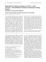
Eq. (5-l) was developed using the conceptual model
of Fig. 5.4. In the model, the slab is supported after
punching by bottom reinforcement draped over the
support in the two directions. If the bottom reinforce-
ment is considered to assume an angle of 30 deg with
respect to the horizontal, reinforcement having an area
equal to that given by Eq. (5-l) will be capable of sup-
porting the load w, within a tributary area equal to
l,l,.
Identical expressions have been obtained by other in-
vestigators using different interpretations of the basic
mechanism.5a.42
The adequacy of Eq. (5-l) has been
demonstrated by numerous experiments.
sa,4z
The reduc-
tions permitted for corner and edge connections result
in an area of reinforcement providing the same theo-
retical resistance as provided for interior connections.
For these exterior connections, l
1
and
I,
are intended to
be the full span dimensions, not the tributary area di-
mensions.
It is noted that only bottom reinforcement is capable
of significant post-punching resistance. To perform as
intended, the bottom reinforcement must be effectively
continuous, and it must be placed directly over the col-
umn and within the column cage. As depicted in Fig.
5.4, top reinforcement is less effective than bottom re-
inforcement because it tends to split the top concrete
cover.
The minimum recommended value of w, equal to
twice the slab dead load is based on Reference 8, which
indicates that the total load resisted by a connection
during construction may be approximately twice the
slab dead load. Where detailed calculations and field
monitoring of construction loads indicate lower loads,
the design may be based on the lower loads.
5.3.2 Connections with beams
5.3.2.1
If the beam depth is less than twice the slab
depth at the support, the provisions of Section 5.3.1
should be followed in both directions.
5.3.2.2 If the beam depth is at least equal to twice
the slab depth, adequate integrity is provided if provi-
sions of
ACI
318 are followed for the transverse beams,
including minimum embedment of bottom bars in the
support.
Progressive collapse has not been a prominent
prob-
lem in structures having beams between supports.
Nonetheless, the value of well anchored bottom bars as
provision against collapse should not be overlooked.
5.4-Anchorage
of reinforcement
5.4.1
General recommendations-Reinforcement
should be anchored on each side of the critical section
by embedment length or end anchorage. At connec-
tions, the critical section for development of reinforce-
ment is at the location of maximum bar stress. At con-
nections in structures having rectangular bays, the
crit-
DESIGN OF SLAB-COLUMN CONNECTIONS
352.1
R-1
5
ical
section may be taken along a line intersecting the that yield is generally anticipated in Type 2 connec-
joint face and perpendicular to the direction of the mo - tions, the modification of Section
5.4.4(d)
is not to be
ment.
applied for the Type 2 connection.
5.4.2 Recommendations for Type I connections-
Reinforcement at connections may be developed by us-
ing hooked bars according to Section 5.4.4, by using
straight bars passing through the connection according
to Section 5.4.5, or by using straight bars terminating
at the connection according to Section 5.4.5.
Where significant strain hardening of reinforcement
is anticipated due to inelastic deformations, 1.25 f,
should be substituted
for
f,
in
Eq. (S-2).
5.4.5 Straight bars terminating at the connection-
The development length
ld
for a straight bar terminat-
ing at a Type 1 connection should be computed as
5.4.3 Recommendations for Type 2 connections-
Reinforcement at connections may be developed by us-
ing hooked bars according to Section 5.4.4, except all
bars terminating in the joint should be hooked within
the transverse reinforcement of the join t
usin g
a
90-deg
hook. Alternately, anchorage may be provided by
straight bars passing through the connection according
to Section 5.4.6. Straight bars should not be termi-
nated within the region of slab comprising the connec-
tion.
fYAb
ld
=
25fl
2
O.O004d,
f,
(5-3)
5.4.4 Hooked bars terminating at the connection-
The development length
lclh
of a bar terminating in a
standard hook is
provided the bar is contained within the core of the
column, with the following modifications:
(a) The length
ld
should be increased by 30 percent
for bars not terminating within the core of the column.
For bars anchored partially within the column core, any
portion of the embedment length not within the con-
fined core should be increased by 30 percent.
(b) The length
ld
should be increased by 30 percent if
the depth of concrete cast in one lift beneath the bar
exceeds 12 in.
f,
db
ldh
= 50
fl
(5-2)
with the following modifications:
(a) The development length should be increased by 30
percent for all-lightweight and sand-lightweight con-
crete.
(b) If transverse reinforcement in the joint is pro-
vided at a spacing less than or equal to three times the
diameter of the bar being developed,
ldh
may be re-
duced by 20 percent within the joint.
(c) For Type 1 connections, if side cover normal to
the plane of the hook is not less than
2%
in., and cover
on the bar extension is not less than 2 in.,
ldh
may be
reduced by 30 percent.
(d) For Type 1 connections, if reinforcement in ex-
cess of that required for strength is provided,
idh
may be
reduced by the ratio A,(required)/A,(provided).
In no case should the length
I,,,,
be less than the
greater of 6 in. or
8db.
For most Type 1 and all Type 2 exterior connections,
bars terminating at a connection will be
anchored
using
a standard hook as defined by ACI 318. The tail exten-
sion of the hook should project toward the midheight
of the joint. The development length given by Eq. (5-2)
is similar to that required by ACI 318 and is evaluated
more fully in work done by ACI Committee
408.jp
The
modifications are to be applied concurrently.
The same length is
specified
for Type I and Type 2
connections, based on the assumption that the effects
of
load reversals for
Type 2 connections will be offset
by more stringent recommendations for joint confine-
ment. These confinement recommendations are equiv-
alent to the benefits from increased concrete cover over
the hook; hence, the modification of Section
5.4.4(c)
is
not applicable to Type 2 connections. In addition, given
(c) The length
I,
should be multiplied by 1.33 for
all-
lightweight concrete, or by 1.18 for sand-lightweight
concrete.
(d) The length
I,
may be reduced for Type
1
connec-
tions by multiplying by the factor A
s
(required)/ A
s
(provided) where reinforcement is provided in excess of
that required for strength.
The recommended development length is similar to
that required by ACI 318.
Where the bar is not contained within the core of the
column,
l
d
should be increased as recommended in Ref-
erence
59
to account for the greater tendency toward
splitting when concrete cover is small.
For Type 2 connections, straight bars should not ter-
minate in the region
of
slab comprising the connection.
5.4.6 Bars passing through the joint-For Type 2
connections, all straight slab bars passing through the
joint should be selected such that
h/d,
3
15
(5-4)
where
h,
is the joint dimension parallel to the bar. No
special restrictions are made for column bars or for
Type 1 connections.
Straight slab bars are likely to slip within a joint dur-
ing repeated inelastic lateral load reversals (ACI
352R,
Reference 60). In slabs of usual thickness, slip of rein-
forcement can result in
significant
reduction of lateral
load
stiffness.6’
The purpose of the recommended ratio
between bar size and joint dimension is to limit, but not
eliminate, slippage of the bars through the connection.
The recommended ratio is intended to avoid unusually
large diameter slab bars and will not
influence
propor-
tions in typical designs.
352.1R-16
MANUAL OF CONCRETE PRACTICE
CHAPTER 6-REFERENCES
6.1-Recommended references
American Concrete Institute
318-83
(1986) Building Code Requirements
for Reinforced Concrete
318R-83
Commentary on Building Code Re-
quirements for Reinforced Concrete
423.3R-83
Recommendations for Concrete
Members Prestressed with Unbonded
Tendons
352 R-85
Recommendations for Design of
Beam-Column Joints in Monolithic
Reinforced Concrete Structures
American National Standards Institute
ANSI
A.58.1-82
Building Code Requirements for
Minimum Design Loads in Buildings
and Other Structures
International Conference of Building Officials
UBC-1985
Uniform Building Code
6.2-Cited references
1. “Flat Slab Breaks from Columns in Building,” Engineering
News Record, Oct.
11,
1956, pp. 24-25.
2. “Building Collapse Blamed on Design, Construction,” Engi-
neering News-Record,
July 15, 1971, p. 19.
3. “Collapse Kills Five and Destroys Large Portion of 26-Story
Apart
ment
Building,“Engineering
News-Record,
Mar. 8, 1973, p. 13,
and subsequent articles on Mar. 15, 1973,
p.
12, May 31, 1973,
p,
13,
and June 14, 1973,
p.
15.
4. Leyendecker, Edgar V., and Fattal, S. George, “Investigation of
the Skyline Plaza Collapse in Fairfax County, Virginia,” Building
Science Series No. 94,
National Bureau of Standards, Washington,
DC., Feb. 1977, 88 pp.
5. ACI-ASCE Committee 426, “The Shear Strength of Reinforced
Concrete Members-Slabs,” Proceedings, ASCE, V. 100,
ST8,
Aug.
1974, pp. 1543-1591.
6. Rosenblueth, Emilio, and
Meli,
Roberto, “The 1985 Earth-
quake: Causes and Effects in Mexico City,” Concrete International:
Design
&
Construction, V.
8,
No. 5, May 1986, pp. 23-34.
7. Lew, H. S.; Carino,
N.
J.; and Fattal, S. G., “Cause of the
Condominium Collapse in Cocoa Beach, Florida,” Concrete Inter-
national: Design
&
Construction, V. 4, No. 8, Aug. 1982, pp. 64-73.
Also, Discussion, V. 5, No. 6, June 1983, pp. 58-61.
8.
AgarwaI,
R. K., and Gardner, Noel J., “Form and Shore Re-
quirements for Multistory Flat Slab Type Buildings,”
ACI JOURNAL,
Proceedings
V.
71, No. 11, NOV. 1974, pp. 559-569.
9. Sbarounis, John A.,“Multistory Flat Plate Buildings,” Con-
crete International: Design & Construction,
V.
6, No. 2, Feb. 1984,
pp. 70-77.
10. Lew,
H.
S.; Carino,
N.
J.; Fattal, S. G.; and Batts,
M.
E.,
“Investigation of Construction Failure of Harbour Cay Condomin-
ium in Cocoa Beach, Florida,” Building Science Series No. 145 , Na-
tional Bureau of Standards, Washington, D. C., Aug. 1982, 135 pp.
11. ACI-ASCE Committee 426,“Suggested Revisions to Shear
Provisions for Building Codes,”
ACI
JOURNAL,
Proceedings
V.
74,
No. 9, Sept. 1977, pp, 458-468.
12.
Meli,
Robert, and Rodriguez, Mario, “Waffle Flat Plate-Col-
umn Connections Under Alternating Loads,” Bulletin d’information
No, 132,
ComitC
Euro-International du Beton, Paris, Apr. 1979, PP.
45-52.
13. Park, Robert, and Gamble, William L., Reinforced Concrete
Slabs,
John Wiley
&
Sons, New York, 1980, 618 pp.
14. Vanderbilt, M. Daniel,
“
Shear Strength of Continuous Plates,”
Proceedings, ASCE, V. 98,
ST5,
May 1972, pp.
961-973.
15. Hawkins, N. M.,
“Shear Strength of Slabs with Moments
Transferred to Columns,”
Shear in Reinforced Concrete, SP-42,
American Concrete Institute, Detroit, 1974, pp, 817-846.
16.
Rangan,
B.
Vijaya, and Hall, A. S., “Moment and Shear
Transfer Between Slab and Edge Column,” ACI JOURNAL, Procee
d-
ings
V. 5, No. 3, May-June 1983, pp.
183-191.
17.
Hawkins, N.
M.,
and Corley. W. G., “Moment Transfer to
Columns in Slabs with Shearhead Reinforcement,” Shear in Rein-
forced Concrete,
SP-42, American Concrete Institute, Detroit, 1974,
pp. 847-879.
18. Corley, W. Gene, and Hawkins, Neil M., “Shearhead Rein-
forcement for Slabs,” ACI JOURNAL, Proceedings V. 65, No. 10,
Oct
.
1968,
pp. 81l-824.
19. Paulay, T., and Taylor, R. G.,
“Slab Coupling of Earthquake
Resisting Shear Walls,”
ACI
JOURNAL, Proceedings V. 78, No. 2,
Mar Apr. 1981, pp.
130-140.
20. Schwaighofer, Joseph, and Collins, Michael P., “An Experi-
mental Study of the Behavior of Reinforced Concrete Coupling
Slabs,”
ACI
Journal, Proceedings V. 74, No. 3, Mar. 1977, pp.
123-
127.
21. Hawkins, Neil M.,
“Lateral Load Resistance of Unbonded
Post-Tensioned Flat Plate Construction,”
Journal,
Prestressed Con-
crete Institute, V. 26, No,
1,
Jan Feb. 1981, pp
94-115.
22. Burns, Ned H., and Hemakom, Roongroj, “Test of Post-Ten-
sioned Flat Plate With Banded Tendons,” Journal of Structural En-
gineering,
ASCE, V. 111, No. 9, Sept. 1985, pp. 1899-1915.
23. Kosut, Gary M.; Burns, Ned H.; and Winter, C. Victor, “Test
of Four-Panel Post-Tensioned Flat Plate,” Journal of Structural En-
gineering,
ASCE, V. 111, No. 9, Sept. 1985, pp.
1916-1929.
24.
Smith, Stephen W., and Burns, Ned H., “Post-Tensioned Flat
Plate to Column Connection Behavior,” Journal
, Prestressed Con-
crete Institute, V. 19, No. 3, May-June 1974,
pp.74-91.
25. Design of Post-Tensioned Slabs, Post-Tensioning Institute,
Glenview, 1977, 52 pp.
26. Trongtham, N., and Hawkins, N. M., “Moment Transfer to
Columns in Unbonded Post-Tensioned Prestressed Concrete Slabs,”
Report No. SM-77-3, Department of Civil Engineering, University of
Washington, Seattle, Oct. 1977.
27. Liu. Xi-La; Chen, Wai-Fah; and Bowman, Mark
D.,
“Con-
struction Loads on Supporting Floors,” Concrete International: De-
sign & Construction,
V. 7, No. 12, Dec. 1985, pp. 21-26.
28. Grundy, Paul, and Kabaila, A.,
“Construction Loads on Slabs
with Shored
Formwork
in Multistory Buildings,”
ACI
Journal,
Pro-
ceedings V. 60, No. 12, Dec.
1963,
pp. 1729-1738.
29. Johansen,
K.
W., Yield Line Theory, Cement and Concrete
Association, London, 1962, 181 pp.
30. Hatcher. David
S.;
Sozen,
Mete A.; and Siess, Chester P.,
“Test of a Reinforced Concrete Flat Plate,” Proceedings,
ASCE, V.
91,
ST5,
Oct. 1965, pp. 205-231.
31. Criswell, M. E.,“Design and Testing of
a
Blast Resistant R/C
Slab System,” Report No. N-72-10, U. S. Army Engineer Water-
ways Experiment Station, Vicksburg, Nov. 1972.
32. Vanderbilt,
M.
Daniel, and Corley,
W.
Gene, “Frame Analy-
sis of Concrete Buildings,”
Concrete International: Design & Con-
struction,
V. 5, No. 12, Dec. 1983, pp. 33-43.
33.
Moehle,
Jack P., and
Diebold,
John W., “Lateral Load Re-
sponse of Flat-Plate Frame,”Journal of Structural Engineering,
ASCE,
V.
111, No. 10, Oct. 1985, pp. 2149-2164.
34. Mulcahy,
J.
F., and Rotter, J. M., “Moment Rotation Cha
acteristics of Flat Plate and Column Systems,”
ACI
JOURNAL
, Pro-
ceedings
V. 80, No. 2, Mar Apr. 1983, pp. 85-92.
35. Darvall, Peter, and Allen, Fred, “Lateral Load Effective Width
of Flat Plates with Drop Panels,”
ACI
JOURNAL, Proceedings V. 81,
No. 6, Nov Dec., 1984, pp. 613-617.
36. Regan, P. E., and Braestrup, M. W., “Punching Shear in
Reinforced Concrete,” Bulletin d’lnformation No. 168,
Comite
Euro-
International du
B&on,
Lausanne, Jan. 1985, 232 pp.
37. Cracking, Deflection, and Ultimate Load of Concrete Slab
Systems, SP-30,
American Concrete Institute,
Detroit,
1971, 382 pp.
38. Shear in Reinforced Concrete, SP-42, American Concrete In-
stitute, Detroit, 1974, 949 pp.
39. Alexander, Scott D. B., and Simmonds, Sidney H., “Ultimate
Strength of Slab-Column Connections,” ACI Structural Journal, V.
84, No. 3,
May-June 1987, pp. 255-261.
DESIGN OF SLAB.COLUMN CONNECTIONS
352.1 R-17
40. Simmonds, Sidney H., and Alexander, Scott
D.
B., “Truss
Model for Edge Column-Slab Connections,” ACI Structural Jour-
nal, V. 84, No. 4, July-Aug. 1987, pp.
296-303.
41. Park, Robert, and Islam, Shafiqul, “Strength of Slab-Column
Connections with Shear and Unbalanced Flexure,” Proceedings,
ASCE,
V.
102, ST9, Sept. 1976, pp.
1879-1901.
42. Hawkins, N. M., and Mitchell,
D.,
“Progressive Collapse of
Flat Plate Structures,”
ACI
J
OURNAL
, Proceedings V. 76, No. 7, July
1979, pp. 775-808.
43.
Dilger,
Walter H., and Ghali,
Amin,
“Shear Reinforcement for
Concrete Slabs,” Proceedings, ASCE, V. 107, ST12, Dec. 1981, pp.
2403-2420.
44. Ivy, Charles B.; Ivey, Don L.; and
Buth,
Eugene, “Shear Ca-
pacity of Lightweight Concrete Flat Slabs,”
ACI
JOURNAL., Proceed-
ings V. 66, No. 6, June 1969, pp. 490-493.
45. Zsutty, Theodore C.,
“Beam Shear Strength Predictions by
Analysis of Existing Data,”
ACI
JOURNAL, Proceedings V. 65, No.
11, Nov. 1968, pp,
943-951.
46. Moehle, Jack P.,“Strength of Slab-Column Edge Connec-
tions,” ACI Structural Journal, V. 85, No. 1, Jan Feb. 1988, pp.
89-
98.
47. Pan, Austin, and Moehle, Jack P., “Lateral Displacement
Ductility of Reinforced Concrete Slab-Column Connections,” to be
published in ACI Structural Journal.
48. Morrison,
Denby
G.; Hirasawa, Ikuo; and
Sozen,
Mete A.,
“Lateral-Load Tests of R/C Slab-Column Connections,” Journal of
Structural Engineering, ASCE, V. 109, No. 11, Nov. 1983, pp. 2698-
2714.
49. Hawkins, Neil M.,
“Seismic Response Constraints for Slab
Systems,” Earthquake-Resistant Reinforced Concrete Building Con-
struction, University of California, Berkeley, 1977, V. 3, pp.
1253-
1275.
50.
Hanson, Norman W., and Hanson, John M., “Shear and Mo-
ment Transfer Between Concrete Slabs and Columns,” Journal, PCA
Research and Development Laboratories, V. IO, No. 1, Jan. 1968,
pp,
2-16.
51. Islam, Shafiqul, and Park, Robert, “Tests on Slab-Column
Connections with Shear and Unbalanced Flexure,” Proceedings,
ASCE, V. 102, ST3, Mar. 1976, pp. 549-568.
52.
Zee,
H.
L., and Moehle, J. P.,
“Behavior of Interior and Ex-
terior Flat Plate Connections Subjected to Inelastic Load Reversals,”
Report No. UCB/EERC-84/07, Earthquake Engineering Research
Center, University of California, Berkeley, Aug. 1984, 130 pp.
53. Collins, Michael P,, and Mitchell,
Denis,
“Shear and Torsion
Design of Prestressed and Non-Prestressed Concrete Beams,” Jour-
nal, Prestressed Concrete Institute, V. 25, No. 5, Sept Oct. 1980, pp.
32-100.
54. Hanson, John M.,
“Influence of Embedded Service Ducts on
Strength of Flat-Plate Structures,” Research and Development
Bul-
letin
No.
RD005.01D,
Portland Cement Association, Skokie, 1970, 16
PP-
55. Zaghlool,
E.
Ramzy F., and de Paiva, H. A.
Rawdon,
“Tests
of Flat-Plate Corner Column-Slab Connections,” Proceedings,
ASCE, V. 99, ST3, Mar. 1973, pp. 551-572.
56.
Rangan,
B. Vijaya, and Hall, A.
S.,
“Moment Redistribution
in Flat Plate Floors,”
ACI
Journal, Proceedings V. 81, NO. 6, NOV
Dec. 1984, pp. 601-608.
57. Sheikh,
Shamin
A., and Uzumeri, S. M., “Strength and Duc-
tility of Tied Concrete Columns,” Proceedings, ASCE, V.
106,
ST5,
May 1980, pp. 1079-1102.
58, Mitchell,
Denis,
and Cook, William D., “Preventing Progres-
sive Collapse of Slab Structures,
”
Journal of Structural Engineering,
ASCE,
V.
110, No. 7, July 1984, pp.
1513-1532.
59.
ACI
Committee 408,
“Suggested Development, Splice, and
Standard Hook Provisions for Deformed Bars in Tension,” (AC1
408.1R-79), American Concrete Institute, Detroit, 1979, 3 pp.
60,
Bertero,
V. V.; Popov, E. P.; and Forzani, B., “Seismic Be-
havior of Lightweight Concrete Beam-Column Subassemblages,”
ACI
J
OURNAL
., Proceedings V. 77, No. 1, Jan Feb., 1980, pp. 44-52.
61. Hawkins, N. M.,
“Lateral Load Design Considerations for Flat
Plate Structures,” Nonlinear Design of Concrete Structures, Study
No.
14, University of Waterloo Press, 1980, pp. 581-613.
EXAMPLES*
Example 1
-
Design of an edge connection subjected
to gravity loading
/
Column
16''x16''
I
+8”
Slab
I_
e2=1s
/
f;’
= 4000 psi
f,
= 60,000 psi
L = 40 psf
D= 115psf
Type 1 connection
(2.2.2)
Design forces
U
=
1.4D
+
1.7L
v.
= 38.6 kips
Mub
= 580 kip-in. at centroid of slab critical section
Check shear
Assume
#4
bars each way,
%-in.
cover
d = (7 + 6.5)/2 = 6.75 in.
b,
= 16 + 6.75 +
2(12
+
6.75/2)
= 53.5 in.
A
cs
= b.d = 53.5 x 6.75 = 361 in.
V.=
V,=4Ac,fi=4x361
x
m
=
91,300
lb = 91.3 kips
(2.1)
(4.2.1.1)
V,
=
4
V.
= 0.85 x 91.3 = 77.6 kips
V./V, =
38.6/77.7
= 0.50 < 0.75, therefore, OK
(4.2.1.2b)
Check moment transfer
c,
+
2c,
=
16
+ 2 x 12 = 40 in.
+A&
=
+pbd’&
(1
-
0.59~
&If: )
(5.1.lb)
2
A4.
= 580
kips-in
which requires
p
= 0.0058; A, = 1.62
in.’
Use nine
#4
bars
Reinforcement details
Top reinforcement perpendicular to the slab edge
spacing
Q
0.75d
= 5.1 in.
Development length of hooks
L
=
Kd,)/(5Oa)
(5.1.5b)
= (60,000 x
0.5)/(50-)
= 9.5 in.
(5.4.4)
Structural integrity reinforcement
(5.3.1)
w.
=
greater of (1.40 +
1.7L)
and
(2D)
= 0.230 ksf
A, =
(%)(0.5w.I,~,)/(+_&)
I=
(L/1)(0.5
x 0.230 x 22.5 x
15)/(0.9
x
60)
=
0.48
in’.
Use two
#5
bottom bars each way passing through column
cage.
*N
umbers in parentheses refer to sections of this report.
352.1R.18
MANUAL OF CONCRETE PRACTICE
Final deslgnn
-
Example 1
Column
16”x16”
h
2-#4mln
-
2-#5
Plan
1
L-4
12”>
I
d
I
c,+
4h
=
48" (5.1.5b) ,
.
ection
B-B
c2=
16”
I
I
Temp. and
(
Shrlnkage
I
(typ.)
8’
7‘
7
I
I
I
I
#4
added
I
ection
A-A
Example 2
jecte
d
-
Design of a corner connectlon sub-
to gravity loading
k
Panel
Y
I-"
Column
l&l<
Column
51
Mx
@
X
%
b
ti8”
Slab
6
IL
Pad
I
11.25’
)I
f:
= 4000
psi
f,
= 60,000 psi
L = 40psf
D = 115 psf
Type 1
connection
Design forces
U
= 1.40 +
1.7L
V.
= 19.3 kip
Mvbr
= 290 kip-in.
MM,,
= 190 kip-in.
at centroid of slab critical section
(2.2.2)
Section C-C
Check shear
Assume
#3
bars each way,
%-in.
cover
d = (7.06 +
6.69)/2
= 6.88 in.
b.
=
2(16
+
6.88/2)
= 38.9 in.
(2.1)
A
cs
= 38.9 x 6.88 = 268 in.
(4.2.1.1)
V,
=
V,
= 4 A
cs
fl
= 4 x 268 x
m
= 67,800 lb = 67.8
kips
V.
= +V. = 0.85 x 67.8 = 57.5 kips
Vu/V,
= 19.3/57.5 = 0.34 < 0.75, therefore, OK
(4.2.1.2b)
Check moment transfer
c,
+ c
t
= 16 + 16 = 32 in.
@MN
3
MvbX
= 290 kip-in.
which requires
p,
= 0.0035; A, = 0.78 in.
2
Use eight
#3
bars
(5.l.lb)
@M,
3
MubY
= 190 kip-in.
which requires
p,
= 0.0025;
A,?
= 0.54
in.*
Use five
#3
bars
Reinforcement
details
Top reinforcement perpendicular to the slab edge
spacing <
0.75d
= 5.1 in.
(5.1.5b)
Development length of hooks
Id*
=
(fid,j/5Oa)
= 7.1 in.
Structural integrity reinforcement
W,”
= 0.230 ksf as in Example
I
A
mm
= (~)(0.5%~,W(~JJ
=
(%)(0.5
x 0.230 x 22.5 x
15)/(0.9
x 60)
= 0.36 in.
2
(5.4.4)
(5.3.1)
Use two
#4
bottom bars each way passing through column cage.
DESIGN OF SLAB-COLUMN CONNECTIONS
352. 1R-19
Final design
-
Example 2
c2+
cp
c2+
2h
= 32”
lri
Temp. and
Note:
#4
bottom bars placed
through column for protection
against progressive collapse shall
have standard hooks (not shown).
Plan
2-#4
ecti on B-B
Example 3
-
Ed
biaxial moment
LB
e connection subjected to
ue to gravity and wind loading
r
Cdumn 12"x24"
M
uby
kips-in.
Load
combination
l-
Wind
direction
V”,
kips
(1)
;:y;
+
(2)
;‘;‘X;“”
+
1.73
(3)
;7;(;;40
+
1:7w)
(4)
0.9D
+
1.3w
(5)
:;JDw+
I
40.5
30.4
34.8
18.3
22.1
I
ki%n.
-572
-
743
KY:
kios-In.
M
“brl
kios-in.
-394
-
296
-413
-310
-
429
-610
-
623
+ 59
703 -
185
-
257
-
177
+144
+ 137
L
Notes:
M,
and M are fle
xural moments in the slab column strip.
Mubr
and
h&
are moments
transferred
to the
connection
at
the
cen-
troid
of the slab critical section. For moment in the x-direction, no sign
is indicated. For moment
in the y-direction, values are positive if the
transfer moment tends to place bottom slab steel in tension.
Vu
varies depending on whether the wind is considered along the
pos-
itive or negative direction of the
x-
or y-axes. Only the larger value for
each load combination is tabulated.
225’
I
t
Panel
A
cs
= 61.5 x 6.75 = 415 in.
2
V.
=
V,
= 4
fl
A
cs
= 4 x
m
x 415 = 105 kips
(4.2.1.1)
V,
= +V, = 0.85 x 105 = 89.3 kips
Moment transfer in x-direction:
The maximum transfer moments in the x-direction occur for
loading cases (2) and (4). Loading case (4) must be checked be-
cause it has the larger moment, and loading case (2) must be
checked because it has the larger shear. Both cases involve biax-
ial moment transfer. Section
4.2.1.2(c)
is followed.
For loading case (2)
v,
>
V,
+
a
(M.bx
+
M.,)&
=
30.4 +
3.5(690)/61.5
= 69.7 kips, OK
For loading case (4)
lf2
2
18.3 +
3.5(703)/61.5
=
58.3 kips, OK
fl’
= 4000 psi
f,
= 60,000 psi
L = 40psf
D =
115psf
Type 1 connection
(2.2.2)
Design forces
U
=
1.4D +
1.7L
>
0.75(1.4D
+
1.7L
+
1.7W)
2
0.9 + 1.3W
Check shear
Basic data
d = 6.75 in.
b,,
=
24 + 6.75 +
2(12
+ 6.75/2) = 61.5 in.
(2.1)
352.1
R-20
MANUAL OF CONCRETE PRACTICE
Final design-Example 3
G
Column
12"x24"
l.v=
<-
BL
-)B
A
A
Section A-A
Temp. and
Shrinkage
top and bottom
within
column strip
Section B-B
Note:
Mvbr
is taken equal to zero in the preceding because
V./V, < 0.75.
Moment transfer in y-direction:
The maximum moment transfer in the y-direction occurs un-
der
uniaxial
moment transfer. According to Section
4.2.1.2(b),
effects of moment transfer on shear are ignored because VJV,
<
0.75.
Check flexure
Reinforcement in x-direction:
The column strip (51 in.) is designed to carry the total
column
strip
flexural
moment
I&,
requiring eleven
#4
top and
#4
at 12
in. bottom (temperature and shrinkage).
For moment transfer
Y
v
.
=
1
-
l/(1 + 0.66&Q =
(4.2.1.2a)
= 1
-
l/(1 +
0.66-J!!)
= 0.49
W%
= (1
-
yJ(703)
= 359 kip-in.
(5.1.lb)
Transfer width =
c,
+
1.5h
= 24 in.
The column strip bars already in place will suffice if dis-
tributed uniformly in column strip.
Note:
5A4uw/boVu
>
0.6,
therefore place temperature and shrink-
age reinforcement at the bottom.
(5.1.3b)
Reinforcement in y-direction:
The entire moment
hf.,
is to be resisted in flexure
(5.1.lb)
by reinforcement within transfer width equal to
c,
+
2c,
= 24 + 2 x 12 = 48 in.
For
Mvbv
=
-
623 kipin., provide nine
#4
top.
For
Muqr
=
+ 146 kip-in., provide
#4
@ 12 in, (temperature
and shrinkage).
Check spacing < 0.75d, OK
(5.1.5b)
Check development,
1,
= 9.5 in., OK
(5.4.4)
Structural integrity reinforcement
A,
=
(~)(0.5W,W(o&)
=
(%)(0.5
x 0.229 x 22.5 x
15)/(0.9
x 60)
= 0.48
in.z
(5.3.1)
Use three
#4
bottom bars each direction through column cage.
Example 4
-
Design of an interior connection
with shear capital
f:
= 4000 psi
f,
= 60,000 psi
L = 250 psf
D =
20 psf plus self weight
Type 1 connection
Design forces
U
= 1.4D +
1.7L
Slab reinforcement
#4
bars each way.
(2.2.2)
DESIGN OF SLAB-COLUMN CONNECTIONS
352.1 R.21
Check shear
(a) Around column
V.
= 233 kips,
Mub
=
300
k-in,
MJV,
= 1.29 in. <
0.2d.
therefore, ignore moment transfer
d = 10.75 in.
(3.2.2)
b. = 4
x
(10.75 + 24) =
139in.
A
cs
= 139
x
10.75 = 1490 in.
2
(4.2.1.1)
V.=
V,=4flA,=4~
1490Xm=377kips
V,
=
6
V.
= 0.85 X 377 = 320 kips
V,
<
V,, therefore, OK
(4.2.1.1)
(b)
Around shear capital
V.
= 225 kips
d = 6.75 in.
b, = 4 X (48 + 6.75) = 219 in.
b/d = 219/6.75 = 32.4, therefore,
C.
= 0.75
(Table 1)
A
cs
= 219 x 6.75 =
1480it1.~
(4.2.1.1)
V,
= C,V, = 0.75 x 4 x 1480 x
&@%
= 281 kips
V,
= +
V,
= 0.85 x 281 = 238 kips
Vu
<
V,. therefore, OK
(4.2.1.1)
Reinforcement details
Provide slab flexural steel to resist total slab moments as per AC1
318.
No requirements for moment transfer.
Provide structural integrity reinforcement as per Section 5.3.1
and as illustrated in previous examples.
Example 5
-
Design of an interior connec
tion re-
sisting seismic loads
+.
)
q
i
~
‘-7
P
8’ Slab
I
I
I
w
Final
design
-
Example 5
f:
= 4000 psi
f,
= 60,000 psi
L = 50 psf
D = 115 psf
Type 2 connection
(2.2.2)
Design forces
U
= 1.4D
+
1.7L
2
0.75(1.4D
+
1.7L
+
1.87E)
2
0.9D +
1.43W
Load combination
V
K
Mm
k$
kip-in.
kip-in.
(1) 1.4D +
1.7L
97
1450
(2)
0.75(1.4D
+
1.7L
+
1.87E)
1440
780
(3) 0.9D +
1.43E
::
960 780
Notes: M. = column strip total moment.
M = transfer moment.
Check shear
Assume
#4
bars each way, %-in. cover.
d = 6.75 in. (as per Example 1)
b,
= 4 x (22 + 6.75) = 115 in.
A, = 6.75 x 115 = 776 in.
For nonseismic loads
(2.1)
(4.2.1.1)
V,
=
V,
=
4 A,
fl
= 4 X 776 X
@i%
= 196 kips
V.
= +
V,
= 0.85 x 196 =
I67
kips > 97 kips, OK
For seismic loads
V,
= C,
V,
= 0.75 x 196 = 147 kips
(C,
= 0.75 for seismic loads as per Table 1)
V,
= +
V,
= 0.85 x
147
= 125 kips
(4.2.1.1)
Check moment transfer
V,
+ a
(M,,
+
M&/b,
= 73 + 5 x 780/l 15
= 107 kips <
V.,
OK
(4.2.1.2c)
Check maximum permitted vertical shear
V,,
= 0.4
V,
= 0.4 x 196 = 78 kips > 73 kips, OK
(4.2.1.2d)
Reinforcement requirements
Column strip flexural strength requirements are met by placing
14
#8
bars uniformly across the 10 ft wide column strip.
Moment transfer strength is checked as follows
y, = 1
-
y.
= 0.6
(5.1.la)
Steel is required within
c,
+
3h
= 46 in. to resist
flexural
moment of
valuer,&
= 0.6 x 780 = 470 kip-in.
Reinforcement placed for total column strip moment (as per
previous paragraph) is adequate.
Check if bottom steel is required for moment transfer
(5.1.3b)
5M.,,/b.V,
= 5 x
780/(115
x 41) = 0.83 > 0.6
Therefore minimum reinforcement requirements must be met.
Provide
#
4 at 16 in. within width
c,
+ 4
h
= 54 in., result-
ing in p’f, = 111 psi > 100 psi, OK.
Structural integrity reinforcement
A,m
=
K’.5~JU(~~~
(5.3.1)
= (0.5 x 0.246 x 20 x
20)/(0.9
x 60) = 0.91 in.’
Use three
#5
bottom bars each way passing through column
cage.
Check maximum reinforcement
Within
c,
+
3h
= 46 in.,
p
+
p’
$
0.75
p*,.
OK
Check maximum bar spacing
S,,
=
2h
= 16 in., OK
(5.1.4)
(5.1.2)
Section
A-A
352.1
R-22
MANUAL OF CONCRETE PRACTICE
NOTATION
cross-sectional area of reinforcing bar. in.
2
cross-sectional area of the slab critical section, in.
2
total area of steel at a cross section, in.
2
minimum area of effectively continuous bottom slab
bars in each principal direction placed over the sup-
port for resistance to progressive collapse, in.
2
beam width, in.
perimeter of the slab critical section, in.
dimension of the column transverse to the direction of
moment transferred to the column, in.
dimension of the column transverse to the direction of
moment transferred to the column, in.
distance from the inner face of the column to the slab
edge measured perpendicular to the edge, but not to
exceed c
1
product of all appropriate modification factors in Ta-
ble 4.1
slab effective depth, taken as the average of the depths
from extreme concrete compression fiber to tension
steel in two orthogonal directions, in.
diameter of slab reinforcing bar, in.
effective depth of transverse beam at connection, in.
concrete compression strength, psi
design yield stress of slab reinforcement, psi
slab thickness, in.
joint dimension in direction parallel to that of a
straight slab bar passing through the joint, in.
development length of straight bar, in.
development length of hooked bar, in.
center-to-center spans in each principal direction
moment transferred to the column
simultaneous moments transferred to the column and
acting in the two principal directions about the geo-
metric centroid of the slab critical section
basic shear strength of concrete without modifications
in Table 4.1, lb
nominal shear strength in the absence of moment
transfer, lb
design shear strength in the absence of moment trans-
fer, lb
factored direct shear force acting on slab critical sec-
tion
factored ultimate load, but not less than twice the slab
dead load, to be considered for resistance to progres-
sive collapse
coefficient to Eq. (4.4)
ratio of long to short dimensions of the column cross
section
ratio of lengths of the slab critical section measured
parallel and transverse to the direction of moment
transfer, respectively
steel ratio for bottom slab steel in one direction at the
connection
strength reduction factor
fractin
of transfer moment at slab-column connection
that is to be carried by slab flexure, same as
ACI
3 18
definition of
v,
fraction of transfer moment at slab-column connection
that is to be carried by eccentric shear stresses on the
slab critical section, same as
ACI
318 definition of
yV
CONVERSION FACTORS
1 in. = 25.4 mm
1 psi = 6895 N/m
2
1 lb = 4.448 N
1
kip-in. = 0.113
kN-m
This
reportt
was submitted to letter ballot of the committee and was
ap-
proved
in
accordance with
ACI
balloting procedures.
I
THE FOLLOWING DISCUSSIONS, WHICH WERE PUBLISHED IN THE JULY-AUGUST 1989 ACI Structural
Journal (PP.
496-499),
ARE NOT PART OF THE REPORT ACI 352.1 R-89, BUT ARE PROVIDED AS ADDI-
TIONAL INFORMATION TO THE READER.
1
Recommendations for Design of Slab-Column Connections in Monolithic Reinforced
Concrete Structures.
Report by ACI-ASCE Committee 352
Discussion by
Amin
Ghali,
B.
Vijaya
Rangan,
and Committee
By
AMIN
GHALI
Member American Concrete Institute, Professor of Civil Engineering,
University of Calagary, Calgary, Alberta, Canada
Section 4.2.1.2 of the report recommends three alter-
nate methods for calculating the strength of slab-col-
umn connections transferring shearing forces and
bending moments. Method (a) is general and applies to
any critical section at interior, edge, or corner col-
umns. In this method, a fraction
yy
of the moment is
assumed transferred by shear stress, which varies lin-
early about the centroid of the slab critical section.
Method (c) uses Eq. (4-4) which “emulates, in alge-
braic form, the eccentric shear model” adopted in
Method (a). Thus, it can be expected that Method (a)
and Eq. (4-4) give the same result. Method (b) ignores
the moment transfer in corner and edge connections
and considers that they have adequate strength when
the shear stress caused by
V,
does not exceed 75 per-
cent of
VJA,.
The assumption involved in Method (a) leads to the
following
equation for the shear stress at any point on
the critical section
*_
(4-5)
where
V,
M,,
and
MY
are the shear force and the mo-
ments about centroidal principal axes x and
y
of the
critical section; A,
I,,
and
I,
are the area and second
moments of area about the same axes.
The positive directions of the coordinates x and
y
and
the forces
V,
M,,
and
MY
are indicated in Fig. A. The
arrows represent a force and moments exerted by the
column on the critical section. Equal and opposite force
and moments representing the effect of the critical sec-
tion on the column* exist but are not shown in Fig. A.
The symbols
h4,
and
MY
represent the fraction of the
moments transferred by shear; that is
yy
multiplied by
the moment transferred between column and slab.
When using Eq.
(4-5),
it should be noted that x and
y
are the critical section centroidal principal axes, which
are not necessarily parallel to the slab edges or to the
principal axes of the column cross section. This will be
the case for the critical section at a corner column or at
any column adjacent to nonsymmetrical openings.
The basic mechanics Eq. (4-5) is derived from the as-
sumption of linear variation of v over the critical sec-
tion and the conditions that v has stress resultants equal
*The
double-headed arrows sho
wn on the
plans
of the slabs in Ex
amples 2
and 3 of the report do not indicate the moment directions unless a mention is
made that the arrows represent the action of the column on the critical
section
or the effect of critical section on the column.
;
-
1
352.1
R-D1
/
I
352.1R-D2
MANUAL OF CONCRETE PRACTICE
v.
M,
AND My REPRESENT
EFFECTS OF COLUMN ON
SLAB CRITICAL SECTION
Fig. A
-
Positive directions of coordinates
x
and y and
of V,
M,
and
M,
to
I’,
M,,
and
MY.
Eq. (4-5) differs from the equation
in Section 11.12.2.4 of the
ACI
318-83
Commentarp2
in that the critical section property
J,,
which the Com-
mentary describes as “analogous to polar moment of
inertia,”
is here replaced by the second moment of
Area I. The reasons for the change are given in Refer-
ence 63, where it is shown that the Commentary equa-
tion gives erroneous results when x and
y
are not
cen-
troidal principal axes, and when they are, the equation
gives slightly smaller stresses than the stresses by Eq.
(4-5). For the remainder of the present discussion, Eq.
(4-5) will be considered applicable in Method (a) of
Section 4.2.1.2. of the Committee 352 report.
Eq. (4.4) of the report implies that the maximum
shear stress at the critical section can be determined by
V
”
m0.x
=
2
+
-&
wf”bl
+
Mu*21
(4-6)
0
where
b,
is the perimiter of the critical section, and
&,
and
Mub2
are the factored moments transferred to the
column about the centroidal principal directions at the
centroid of the critical section. The values of
CY
recom-
mended are 5 for interior and 3.5 for edge connections.
No value is given for corner connections, which prob-
ably means that Eq. (4-6) does not apply in this case.
In fact, when Eq. (4-6) is used for a corner column,
with
CY
= 3.5, it gives a substantially different result
from Eq. (4-5).
The Committee report states that Eq. (4-6) does not
apply when the long-to-short cross-sectional dimen-
sions of the column are greater than two. There are
several other cases not mentioned in the report for
which Eq. (4-6) cannot possibly give the correct maxi-
mum shear stress because the equation does not include
the necessary parameters. Examples of such cases are:
columns with nonrectangular cross-sections,
nonsym-
metrical critical sections due to the presence of open-
ings, and edge connections with slab overhang.
Eq. (4-5) is basic and general and does not need to be
simplified by Eq.
(4-6),
which has so many limitations.
Method
(b)
is based on tests on edge connections that
have indicated that the slab strength in transfer of mo-
ment perpendicular to slab edge is not influenced sig-
nificantly by the shearing force. This phenomenon can
mean that the fraction of moment transferred by shear
is smaller for exterior columns than for interior col-
umns. Thus, in Method (a), different values of the
coefficient
yv
should be used for interior, edge, and
FORCE AND MOMENTS
TRANS-
FORCES AND MOMENTS
FERRED
FROM COLUMN TO SLAB
RESISTED BY SHEAR
Fig. B
-
Top views of a corner-column connection ex-
ample
corner columns. It is also expected that, for edge and
corner columns, the coefficient
yy
becomes zero when
the critical section is sufficiently far from the column
faces. However, research is needed before an adjust-
ment of
yv
can be made.
Method (b) allows substantially higher force and
moment transfer compared to Method (a), as will be
shown below by a numerical example of a corner col-
umn connection. Method (b) can lead to unsafe design
because it extends the results of a test series of edge
connections to corner connections without sufficient
experimental evidence.
EXAMPLE
A corner column of cross section 16 x 16
in.*
is con-
nected to an 8-in. slab with d = 6.88 in. The factored
force and moments transferred from the column to the
slab are indicated in Fig. B.* It is required to deter-
mine, using Method (a), a multiplier
g,
which, when
applied to the transferred force and moment, will make
the connection just safe. Repeat the design using
Method (b) to determine a corresponding multiplier
qb.
Assume that normal weight concrete having
fi
= 4000
psi is used, that
flexural
yielding in the slab is not an-
ticipated, and that the connection is of Type 1.
Method (a)
-
The principal axes of the slab critical
section are inclined 45 deg to the slab edges. The prop-
erties of the critical section are
A =
2(6.875)(19.44)
=
267
in.2
1,
=
$
(13.74)2
= 4208
in.4
1,
=
$(27.49)2
= 16,800
in.4
The transferred moments are multiplied by
yv
= 0.4
and replaced by equivalent components in the principal
x- and y-directions. The shear in the critical section are
to be determined for
V
= 19.3 kips;
h4,
= 136 kips-in.,
MY
= 28 kips-in.
*The
da
ta for
this
example are the same as for Example 2 of the Committee
report. with the exception of the directions of the transferred moments. Here
the directions of the transferred moments are chosen such that they produce
tensile stress in the top slab fiber in directions perpendicular to the inner faces
of the columns. This represents the common case in practice where the mo-
ments are caused by gravity forces on the slab.
j
SLAB-COLUMN CONNECTIONS
352.1 R-D3
The maximum shear stress occurs at Point A, whose
x and
y
coordinates are (0 and 6.87). Maximum shear
stress by Eq. (4-5)
19300
vmQX
=267+
+z
(6.87) +
g(O)
= 72 + 222 + 0 = 294 psi
None of the modification factors of Table 4.1 apply;
thus
C,
= 1.0. The connection will be just safe when
g,
multiplied by
v,_
is equal to
V,/A,
=
4(4fl)
294
g,
= 0.85
(4,/4000);
thus
g.
= 0.73
Method (b)
-
According to this method, the con-
nection will be just safe when
qb
multiplied by 72 psi,
which is the shear stress due to the a vertical force, is
equal to 0.75
4(4fl).
This gives
72
Q,
=
0.75(0.85)
(4,/3000);
thus
gc
= 2.24
From the example just given it can be seen that
Method (b) considers the connection to be safe under
load more than three times the load allowed by Method
(a). Method
(b)
can hardly be considered an alternate to
Method (a).
CONCLUSION
In view of the preceding example, it is suggested that
only Method (a) be retained, with the maximum stress
calculated by Eq. (4-5). A mention may be made that
the value of
yV
can be smaller than the value given by
Eq. (4-3) when the connection is of an exterior column.
REFERENCE
62.
ACI
Committee 318,
“Commentary on Building Code Re-
quirements for Reinforced Concrete (ACI 318R-83).” American
Concrete Institute, Detroit, 1983, 155 pp., and 1986 Supplement.
63. Ghali, Amin, Discussion of Section 11.12.6.2 of “Proposed
Revision to: Building Code Requirements for Reinforced Concrete
(ACI
318-83) (Revised
1986),”
reported by
ACI
Committee 318,
ACI
Structural Journal,
V. 86, No. 3, May-June 1989. p. 329.
By B.
VIJAYA
RANGAN
FACI, Associate Professor and Head, Department of Structural Engineering,
University
of New South Wales, Kensington, New South Wales, Australia
The members of Committee 352 should be congratu-
lated for their report. This discussion deals mainly with
Sections 4.2.1.2(b), and Example 1. The design method
described in these sections of the report is based on the
work of Professor
Moehle.* I am concerned that this
method would lead to overconservative designs in prac-
tice. The following points support my concern:
1. I have reworked Example 1 using
ACI
318-83.
According to the
ACI
Building Code method, the mo-
ment transferred by direct flexure is 375 kips-in., and
therefore 580
-
375 = 205 kips-in. is transferred as
torsion. The combined maximum shear stress due di-
rect shear and moment transfer is found to be 211 psi,
which is less than
44x
= 4 x
O.SS&@Ki
=
215 psi.
The shear strength of the slab is therefore adequate. To
transfer a moment of 375 kips-in. by direct flexure, ad-
equate area steel must be provided in the vicinity of the
column over a width of
c,
+
3h
= 16 + (3 x 8)
=
40
in. This requires
p
= 0.0039; A, = 1.05 in. which
should be compared with
p
= 0.0058; A, = 1.62 in.
given in Example 1. In other words, the proposed
method requires over 50 percent more steel than that
needed by the
ACI
Code method within the same slab
width of 40 in. The
ACI
method has been in use for
more than 20 years, and I am not aware of any evi-
dence showing that it is not adequate. With the advent
of microcomputers and programmable calculators, very
little effort is required to check a slab for adequate
shear strength using the
ACI
method. For these rea-
sons, I fail to see the necessity for the proposed method
that would lead to overconservative designs. Also, the
supporting data for limiting the spacing of bars to a
maximum of
0.75d
is not given in the report.
2. The overconservative nature of the proposed
method is further supported by the results obtained
from a slab specimen tested recently at the University
of New South Wales. The test specimen is similar to the
one I have tested
earlier,16
except that there are no
closed ties in the slab at the edge.
The test specimen is a half-scale model of an edge
connection with the following details: slab thickness =
100 mm (3.94 in.),
d = 82 mm (3.23 in.), c, = 250 mm
(9.84 in.),
c,
= 200 mm (7.87 in.),
f,’
= 48.3 MPa
(7004 psi), and slab steel perpendicular to the free edge
consisted of 6.3 mm (0.25 in.) diameter bars at spac-
ings of 100 mm (3.94 in.) at the top and 115 mm (4.53
in.) at the bottom. In addition, two 8 mm (0.31 in.) di-
ameter bars and two 6.3 mm (0.25 in.) diameter bars
were also placed at the top within the column width.
The yield strength of 6.3 mm bar is 460 MPa (66.7 ksi)
and that of 8 mm bar is 535 MPa (77.6 ksi). The spec-
imen failed in punching shear and the measured forces
at failure are
V,
= 108.2
kN
(24.4 kips) and
&,
= 27.9
kNm
(247 kips-in.). For this specimen,
b,
= 864 mm
(34.0 in.),
V,
= 864 x 82 x
0.34m
= 167.4
kN
(37.7 kips) and
V./V,
=
108.2i167.4
= 0.65 < 0.75.
According to the proposed method, therefore, the
strength of this edge connection is given by the mo-
ment transfer strength of the slab
flexural
steel within
the width of
c,
+
2c,
= 200 + (2 X 250) = 700 mm
(27.6 in.), which is found to be 14.0
kNm
(124
kips-
in.). The ratio of test strength/predicted strength =
27.9/14.0
= 2.0.
I have calculated the strength of this test specimen
using the
ACI
Building Code method. The predicted
moment transfer strength is 20
kNm
(177 kips-in.) and
therefore test value/calculated value = 27.9/20.0 =
1.40.
I have also calculated the strength of this connection
using the simple formula given in the Australian Stan-
dard.
64
The predicted shear strength is 77.3 kN (17.4
kips) and the test/calculated ratio is
108.2/77.3
= 1.40.