parallel computation of the interleaved fast fourier transform with mpi
Bạn đang xem bản rút gọn của tài liệu. Xem và tải ngay bản đầy đủ của tài liệu tại đây (227.91 KB, 72 trang )
PARALLEL COMPUTATION OF THE INTERLEAVED FAST FOURIER
TRANSFORM WITH MPI
A Thesis
Presented to
The Graduate Faculty of The University of Akron
In Partial Fulfillment
of the Requirements for the Degree
Master of Science
Ameen Baig Mirza
December, 2008
ii
PARALLEL COMPUTATION OF THE INTERLEAVED FAST FOURIER
TRANSFORM WITH MPI
Ameen Baig Mirza
Thesis
Approved: Accepted:
_______________________ _______________________
Advisor Department Chair
Dr. Dale H. Mugler Dr. Wolfgang Pelz
_______________________ _______________________
Co-Advisor Dean of the College
Dr. Tim O’Neil Dr. Ronald F. Levant
_______________________ _______________________
Committee Member Dean of the Graduate School
Dr. Kathy J. Liszka Dr. George R. Newkome
_______________________ _______________________
Committee Member Date
Dr. Wolfgang Pelz
iii
ABSTRACT
Fourier Transforms have wide range of applications ranging from signal processing to
astronomy. The advent of digital computers led to the development of the FFT (Fast
Fourier Transform) in 1965. The Fourier Transform algorithm involves many
add/multiply computations involving trigonometric functions, and FFT significantly
increased the speed at which the Fourier transform could be computed. A great deal of
research has been done to optimize the FFT computation to provide much better
computational speed.
The modern advent of parallel computation offers a new opportunity to significantly
increase the speed of computing the Fourier transform. This project provides a C code
implementation of a new parallel method of computing this important transform. This
implementation assigns computational tasks to different processors using the Message
Passing Interface (MPI) library. This method involves parallel computation of the
Discrete Cosine Transform (DCT) as one of the parts. Computation on two different
computer clusters using up to six processors have been performed, results and
comparisons with other implementations are presented.
iv
ACKNOWLEDGEMENTS
First and foremost, I would like to thank my advisor, Dr Dale Mugler for
assigning me this project and his constant support and co-operation until the project
completion.
I would also like to thank my co-advisor Dr. Tim O’Neil for his guidance and
support without him the project couldn’t have been implemented in parallel, I would also
like to thank Dr. Kathy Liszka and Dr. Wolfgang Pelz for their time and effort and
especially for their valuable suggestions on parallelizing the Fast Fourier transform.
I would also like to thank my friends Mahesh Kumar, Radhika Gummadi, and
Venkatesh Pinapala who helped me during the implementation and final phases of this
project.
A special thanks to OSC (Ohio Supercomputer Center) for making the FFT to
work on supercomputer machines which helps me to attain more accurate and optimized
results.
Finally, thanks to my family who were always with me supporting me to achieve
better results and I think without their support I would have been lost. Mom and Dad, I
would not have made this success without you.
v
TABLE OF CONTENTS
Page
LIST OF TABLES viii
LIST OF FIGURES ix
CHAPTER
I. INTRODUCTION 1
1.1 Discrete cosine transform (DCT) 1
1.2 Fast Fourier transforms (FFT) 2
1.3 Message passing interface (MPI) 2
1.4 Contributions and outline 3
II. LITERATURE REVIEW 5
2.1 Fastest Fourier Transform in the West 6
2.2 Carnegie Mellon University spiral group 7
2.2.1 DFT IP Generators 8
2.2.2 DCT IP Generators 8
2.3 Cooley-Tukey FFT algorithm 9
2.4 Summary 10
III. MATERIALS AND METHOD 11
3.1 DCT using the gg90 algorithm 11
3.2 DCT using the lifting algorithm 14
vi
3.2.1 DCT using the lifting algorithm for 8 data points 15
3.3 Fast Fourier Transform 16
3.3.1 FFT using the gg90 algorithm 16
3.4 Construction of n=8 point FFT in parallel 18
3.5 FFT using 16 data point 20
3.6 Summary 21
IV. RESULTS AND DISCUSSION 22
4.1 Hardware configuration of OSC machine 22
4.2 Hardware configuration of the Akron cluster 23
4.3 Discrete cosine transforms 23
4.3.1 DCT using the lifting algorithm 23
4.3.2 Comparison of the lifting algorithm on UA and OSC using 1 processor 25
4.4 Comparison of the gg90 and lifting algorithm 26
4.5 Fast Fourier transforms 28
4.5.1 Real case FFT using 1 processor 28
4.5.2 Comparisons of the real case FFT using 1 processor 29
4.5.3 Complex FFT using 2 processor 30
4.5.4 Comparisons of the complex case FFT using 2 processor 32
4.5.5 Complex case FFT using 6 processor 34
4.5.6 Comparison of complex case FFT using 1, 2 and 6 processor 36
4.5.7 Comparison of complex case FFT in parallel with FFTW 3.2 37
4.6 Summarys 39
vii
V. CONCLUSION 40
5.1 Future work 40
REFERENCES 41
APPENDICES 43
APPENDIX A. TABLES SHOWING THE ACTUAL TIMINGS 44
APPENDIX B. C CODE FOR FAST FOURIER TRANSFORMS 50
viii
LIST OF TABLES
Table Page
2.1 Operation counts for DFT and FFT 6
4.1 Comparing DCT lifting algorithm on 1, 2 and 4 processors 24
4.2 Comparing the lifting algorithm at UA and OSC on 1 processor 25
4.3 Comparing the gg90 and lifting algorithm at UA cluster on 1 processor 27
4.4 Real case FFT using 1 processor 28
4.5 Comparison of real case FFT on 1 processor 29
4.6 Complex case FFT on 2 processor 32
4.7 Comparing complex case FFT using 2 processor 33
4.8 Complex case FFT on 6 processor 35
4.9 Complex case FFT on 1, 2 and 6 processors 36
4.10 Comparison of FFT and FFTW3.2 38
ix
LIST OF FIGURES
Figure Page
2.1 N=8 point decimation in frequency FFT algorithm 10
3.1 gg90 formula for calculating cosine and sine values 12
3.2 Sum-difference for four input data points 12
3.3 Last steps in DCT 13
3.4 DCT for 8 data points 13
3.5 Lifting step for two data points 14
3.6 DCT using lifting step for 8 data points 15
3.7 Sum-difference operation for the input data points 17
3.8 FFT for n=8 data points 19
3.9 FFT for n=16 data points 20
4.1 Comparing lifting algorithm on 1, 2 and 4 processors 24
4.2 Comparing lifting algorithm on 1 processor 26
4.3 Comparing gg90 and lifting algorithm on 1 processor 27
4.4 Real case FFT on 1 processor 29
4.5 Comparison of real case FFT on 1 processor 30
4.6 Implementation of FFT on 2 processor 31
4.7 Complex case FFT on 2 processor 32
4.8 Comparison of complex case FFT using 2 processor 33
x
4.9 Implementation of FFT on 6 processor 34
4.10 Complex case FFT on 6 processor 35
4.11 Complex case FFT on 1, 2 and 6 processor 37
4.12 Comparison of FFT and FFTW 3.2 38
1
CHAPTER I
INTRODUCTION
The discrete Fourier transform has a wide range of applications. More specifically
it is used in signal processing to convert the time domain representation of a signal to the
frequency domain. However the process of conversion is very expensive. Hence an
alternate way to compute the discrete Fourier transform is to use the Fast Fourier
Transform (FFT). This project deals with a new idea of solving the FFT by dividing the
whole problem into parallel blocks and assigning them to parallel nodes to obtain better
timings.
1.1 Discrete Cosine Transform (DCT)
The DCT is central to many kinds of signal and image processing
applications, particularly in video compression. The DCT divides an image into discrete
blocks of pixels each block of pixels has a different importance, for any given finite set of
data points from a real world signal. Similar to the FFT, the DCT transforms a signal or
image from a spatial domain to the frequency domain. It does so by expressing a function
or signal in terms of sums of sinusoidal waveforms that vary in amplitude and frequency.
In particular, there exists a DCT for every Fourier related transform, but the DCT
can only be used only for real data points. There are eight standard discrete cosines
transform, the most common variant of this is being the type-II DCT, which is referred
2
to as simply DCT. In this thesis we try to build a type-IV DCT. The difference between
the type-II and type-IV DCT is that the type-II DCT will generate two data points for the
given input whereas the type-IV DCT will generate blocks of four data points for given
input data points.
1.2 Fast Fourier Transform (FFT)
The main reason why the FFT came into use is to compute discrete Fourier
transforms. It is an efficient algorithm to compute discrete Fourier transforms with a
complexity of O (N log N), where N is the number of data points, as compared to
complexity of O (N
2
). For any given finite set of data points taken from a real-world
signal, the FFT expresses the data points into their component frequencies. It is also
useful in solving the major inverse problem of reconstructing a signal from given
frequency data. The FFT are also of great importance in a wide variety of applications
including digital signal processing, solving partial differential equations and quick
multiplication of large integers. The FFT is also known to be the fastest algorithm to
multiply two polynomials.
1.3 Message Passing Interface (MPI)
There is a continual demand for greater computational speed from a computer
system than is currently possible [2]. There are some specific applications like weather
forecasting, manufacturing applications, engineering calculations and simulations, which
must be performed quickly. High-speed systems are greatly needed in these areas. One
way to increase the computational speed is to use multiple processors to solve a problem.
3
The problem is split into parts, each of which is performed by a separate processor in
parallel. When the multiple processors work in parallel they need an interface by which
they can communicate. The MPI is a library used by multiple processors to send
messages back and forth using send and receive commands. This approach provides a
significant increase in performance.
MPI’s goals are performance, scalability and portability. These features make
MPI the most dominant model used in high performance computing today. It has become
the de facto standard for communication between different processors both for shared
memory and distributed memory. MPI-1 is the standard for traditional message-passing
using shared memory between different processors, whereas MPI-2 is standard for remote
memory, with parallel input/output and dynamic processing using distributed memory for
different processors
In this thesis we attempt to compute the FFT in parallel. We design the algorithm
in such a way that the problem is split into parts with each part executed in parallel and
the final result gathered at the end. We use the MPI library to communicate between
multiple processors.
1.4 Contributions and Outline
In this research, we present the following contributions that are implemented in
the course of designing FFT.
1. We implemented the DCT and FFT. The DCT is built using two new approaches,
a gg90 algorithm and a lifting algorithm.
2. We describe a different ways of implementing the FFT by making the FFT run in
parallel with the DCT, thus making the entire Fourier transform run in parallel.
4
The rest of the thesis is organized as follows
1. Chapter 2 will give detailed information on DCT, FFT and the MPI library. It also
talks about the implementation of FFT by the “fast Fourier transform in the west”.
Mellon University’s “spiral group”, which has the best timings for the DCT and
FFT, will also be discussed.
2. Chapter 3 will describe the algorithms pertaining to the DCT which we
implemented by using two different algorithms. We use the naming conventions
the “gg90 algorithm” and the “lifting algorithm”. We also explain how we are
implementing the FFT in parallel and embedding the DCT along with FFT.
3. Chapter 4 describes the results which we have obtained by implementing the DCT
using the gg90 algorithm and the lifting algorithm, followed by FFT results which
we have obtained by making it run on different processors. Here we also take an
opportunity to explain why the gg90 algorithm is preferred in constructing the
FFT.
4. Chapter 5 describes the conclusions and future work. It also suggests new ways of
obtaining better timings for the FFT and also provides enhancements that can be
made to this algorithm.
5
CHAPTER II
LITERATURE REVIEW
Discrete Fourier transforms are primarily used in signal processing. They are also
used in processing information stored in computers, solving partial differential equations,
and performing convolutions. The discrete Fourier transform can be computed efficiently
using the FFT algorithm.
The FFT has various applications including digital audio recording and image
processing. FFTs are also used in scientific and statistical applications, such as detecting
periodic fluctuations in stock prices and analyzing seismographic information to take
“sonograms” of the inside of the Earth [3]. Due to the vast usage of FFT different
algorithms have been developed over time. We will discuss some of the FFT algorithms
which are currently being used.
The discrete Fourier transform of length N requires time complexity to be O (N
2
)
whereas the time complexity of FFT is O (Nlog
2
N), where N is the number of data points.
The following table shows the significant difference between the operation counts for the
DFT and FFT algorithms [1].
6
Table 2.1 Operation counts for DFT and FFT
N DFT(counts) FFT(counts)
2 4 2
4 16 8
8 64 24
16 256 64
32 1024 160
64 4096 384
128 16384 896
256 65536 2048
512 262144 4608
1024 1048576 10240
2.1 Fastest Fourier Transform in the West (FFTW)
The Fastest Fourier Transform in the West package developed at the
Massachusetts Institute of Technology (MIT) by Matteo Frigo and Steve G. Johnson.
FFTW is a subroutine library for computing the discrete Fourier transform (DFT) in one
or more dimensions, of arbitrary input size, and of both real and complex data [4].
FFTW 3.1.2 is the latest official version of FFTW. Here is a list of some of FFTW's
more interesting features [4]:
1. FFTW supports both one one-dimensional and multi-dimensional transforms.
2. The input data can have arbitrary length. FFTW employs O(n log n) algorithms
for all lengths, including prime numbers.
3. FFTW supports fast transforms of purely real input or output data.
4. FFTW with versions above 3.0 supports transforms of real even/odd data.
7
5. Efficient handling of multiple, strided transforms, which lets the user transform
multiple arrays at once, transform one dimension of a multi-dimensional array, or
transform one field of a multi-component array.
6. Portability to any platform with a C compiler
The FFTW has obtained more accurate and optimized results for FFT. They achieved
more extensive benchmarks on a variety of platforms. Their code is machine
independent. The same program without any modification performs well on all most all
the architectures. Since the code of FFTW is available for free download, we configured
it on the Akron Cluster (cluster2.cs.uakron.edu). We will discuss the comparison of
FFTW results with our algorithm results in the next chapter. FFTW’s performance is
typically superior to any other publicly available FFT software. The authors of FFTW
give three reasons for making their code more superior and faster than others [4]:
1. FFTW uses a variety of algorithms and implementation styles that adapt
themselves to the machine.
2. FFTW uses an explicit divide-and-conquer methodology to take advantage of
the memory hierarchy.
3. FFTW uses a code generator to produce highly optimized routines for
computing small transforms.
2.2 The Carnegie Mellon University Spiral Group
The main goal of Carnegie Mellon University’s “spiral group” [5], is to push the
limit of automation in software and hardware development and to provide optimization
for digital signal processing (DSP) algorithms and other numerical kernels. They provide
a number of online generators for solving DFT and DCT. Their method of solving the
8
DFT is using generators, to create the code for a specific case of N (where N is the
number of data points) which will fetch them more enhanced timings and more compact
code.
2.2.1 DFT IP Generator
The Spiral DFT IP generator [24] is a fast generator for customized DFT soft IP
cores. The user provides variety of input parameters like size of DFT, scaling mode, data
width, constant width, parallelism, twiddle storage method, and FIFO threshold that
control the functionality of the generated core. All these parameters control resource
tradeoffs such as area and throughput as well. After filling in the parameters in the input
form, the resources are dynamically estimated. The output generated is synthesizable
Verilog code for an n-point DFT with parallelism p.
2.2.2 DCT IP Generator
The Spiral DCT IP generator [25] is a fast generator for customized DCT. The
user provides input parameters like DCT size, data width, constant width, data ordering,
scaling mode, parallelism, constant storage method and FIFO threshold that control the
functionality of the generated core. The input parameters also control resource tradeoffs
such as area and throughput. The output generated from the generator is a synthesizable
Verilog code for an n-point DCT (type II) with parallelism p.
Both the DFT and DCT generators take the same input parameters and generate
the specific Verilog code for the specific value of N, where N is number of input data
points. Since the code is specific for specific value of N the time generated is very less.
9
2.3 Cooley-Tukey FFT algorithm
The Cooley-Tukey FFT algorithm is the most common algorithm for developing
FFT. This algorithm uses a recursive way of solving DFT of any arbitrary size N [22].
The technique divides the larger DFT into smaller DFT. Which subsequently reduce the
complexity of their algorithm. If the size of the DFT is N then this algorithm makes
N=N1.N2 where N1 and N2 are smaller DFT’s. The complexity then becomes O (N log
N).
Radix-2 decimation-in-time (DIT) is the most common form of the Cooley-Tukey
algorithm, for any arbitrary size N. Radix-2 DIT divides the size N DFT’s into two
interleaved DFT’s of size N/2. The DFT is defined by the formula [21]
Radix-2 divides the DFT into two equal parts. The first part calculates the Fourier
transform of the even index numbers. The other part calculates the Fourier transform of
the odd index numbers and then finally merges them to get the Fourier transform for the
whole sequence. This will reduce the overall time to O (N log N).
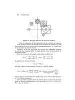
In Figure 2.1, a Cooley-Tukey based decimation in frequency for an 8-point FFT
algorithm is shown:
10
Figure 2.1 N = 8-point decimation-in-frequency FFT algorithm.
The structure describes that given an input N, the algorithm divides it into equal pairs,
and further divides it in a recursive way until single data points are left. Once all the data
points are formed the algorithm then merges them to get the Fourier transform for the
whole sequence.
2.4 Summary
In this chapter, we discussed the FFT models which are currently being used. However
the models provide sequential versions of the FFT. Little amount of research has been
done on developing a parallel version of the FFT. We developed this approach of
implementing the FFT in parallel.
11
CHAPTER III
MATERIALS AND METHODS
In this thesis the DCT is computed by using two different algorithms; the gg90 and the
lifting algorithm. We present gg90 algorithm.
3.1 DCT using the gg90 algorithm.
This algorithm involves three main steps, for n=8.
1. Reorder the input data points.
2. Calculate the cosine and sine values using the gg90 formula.
3. Calculate sum-difference step for the given input points.
For the given input data points for a vector of length 8, first change the order of the input
points. In order to do that, the data points are stored in two different blocks: the even
elements are stored in one block and the odds in the other in reverse order. For example
the 8 data points x0 to x7 would be re-order as x0, x7, x2, x5, x4, x3, x6, x1. Calculate
the cosine and sine values by using the formula.
12
Figure 3.1 gg90 formula for calculating cosine and sine values
Figure 3.1 shows for two data points a, b, the output value of a is calculated as
cos (Φ) a +sin (Φ) b and the output value of b is calculated as sin (Φ) a - cos (Φ) b.
The sum-difference step Figure 3.2 involves sum and difference operations on the input
data points. The points are divided into two halves. The top half performs the addition
operation and the bottom half performs the difference operation.
Figure 3.2 Sum-difference for four input data points
There is a last computation step involved when the data point size is two, as seen in
Figure 3.3, the computation that needs to be performed is a sum-difference of two data
points divided by the square root of 2.
g (Φ)
a
b
cos (Φ) a +sin (Φ) b
sin (Φ) a
–
cos (Φ) b
a
b
c
d
a + c
b + d
a - c
b - d
13
Figure 3.3 Last steps in DCT
Figure 3.4 shows the complete discrete cosine transform computation for 8 data points
[13].
Figure 3.4 DCT for 8 data points
As demonstrated in Figure 3.4 the given input data points are reordered and the cosine
and sine angles are computed. The output values are then operated on by the sum-
difference method. After this first step, the problem is partitioned into two halves. The
top half only requires a sum-difference operation, but the bottom half needs a sum-
0
7
2
5
4
3
6
1
g(1/32) Sumdiff
g(5/8)
g(1/8)
g(13/32)
g(9/32)
g(5/32)
Sumdiff/
√2
Sumdiff/
√2
0
7
2
5
4
3
6
1
Sumdiff
a
b
(a + b)/√2
(a – b)/√2
14
difference and also a cosine and sine multiplication. Finally the last step carries out the
sum-difference operation and then divides by the square root of 2.
3.2 DCT using the lifting algorithm
The steps involved in the lifting algorithm are similar to that of the gg90 algorithm,
except for one step where the cosine and sine are calculated [13, 14].
For the case of N=8 data points:
1. Reorder the input data points.
2. Calculate the cosine and sine values using the lifting formula.
3. Calculate the sum-difference step for the given input points.
Lifting performs the cosine and sine multiplication different from the gg90 algorithm.
After calculating the cosine and sine values for the given input data points, we tabulate
the R value, which is derived by the formula R=(c-1)/s where c and s are the cosine and
sine values.
Figure 3.5 Lifting step for two data points
Computed: c = cos(pi/ 8), s = sin(pi/8) R= (c-1)/s
a
b
L1 + R * L2
L2 = s*L1 - b
L1 = a- R * b
L (Φ)
15
Figure 3.5 shows that for two data point a, b only the R and sine values are used. First
calculate an intermediate value L1=a-R*b which is used to derive the values for the two
data points. The first second data output value is calculated by the formula s*L1 –b. This
value is stored in L2 which is then used to compute the output for the first data point by
the formula L1+R*L2.
3.2.1 DCT using the lifting algorithm for 8 data points
The given input data points are reordered. The even values are stored in order and the odd
values are stored in reverse order. The lifting formula is applied to compute the cosine
and sine values followed by a sum-difference step. After the sum-difference operation the
problem is divided into two halves. The first half performs the normal sum-difference
step and the bottom half performs lifting and the sum-difference step. As seen from
Figure 3.6, the last step involves the sum-difference and then division by the square root
of 2.
Figure 3.6 DCT using lifting step for 8 data points
0
7
2
5
4
3
6
1
L (1/32) Sumdiff
L (5/8)
L (1/8)
L (13/32)
L (9/32)
L (5/32)
Sumdiff/
√2
Sumdiff/
√2
0
7
2
5
4
3
6
1
Sumdiff