ETSI WIDEBAND CDMA STANDARD FOR THE UTRA FDD AIR INTERFACE.pdf
Bạn đang xem bản rút gọn của tài liệu. Xem và tải ngay bản đầy đủ của tài liệu tại đây (298.09 KB, 28 trang )
ETSI WIDEBAND CDMA STANDARD FOR THE UTRA FDD AIR
INTERFACE
by
Nicky Jee-Ngai Yuen
Electrical Engineering 563
Wireless Personal Telecommunications Systems
ETSI WIDEBAND CDMA STANDARD FOR THE UTRA FDD AIR
INTERFACE
Submitted to
Dr. P. Takis Mathiopoulos
The University of British Columbia
by
Nicky Jee-Ngai Yuen
The University of British Columbia
March 30 2001
ii
ABSTRACT
“ETSI Wideband CDMA Standard for the UTRA FDD Air Interface”
by Nicky Yuen
The core requirements for the IMT-2000 air interface technology to be used in Third
Generation (3G) wireless systems are: 1) up to 2 Mbps data rate for local area coverage, 2)
up to 384 kbps data rate for wide area coverage, 3) highly efficient utilization of the spectrum
in contrast to current 1G and 2G systems, and 4) capability to support various multimedia
information sources on an ongoing basis. The radio access technology that was finally
proposed in January of 1998 to meet these criteria was W-CDMA. W-CDMA is based on
Direct Sequence CDMA technology, with a chip rate of 4.096 Mcps. It is designed to be
flexible to accommodate third generation services as well as to be adaptable to current GSM
systems. This paper presents a background to 3G systems, some key features and
technologies of the W-CDMA FDD air interface, and a description of the physical channel
and frame structure.
iii
LIST OF ILLUSTRATIONS
Table 1. Key Parameters of W-CDMA..............................................................................4
Table 2. Physical Channel Format.....................................................................................9
Figure 1. ITU Spectrum Allocation ...................................................................................3
Figure 2. Hierarchical Cell Structure for Smooth Handovers...............................................6
Figure 3. Physical Channel Structure.................................................................................9
Figure 4. Uplink DPDCH/DPCCH Structures..................................................................10
Figure 5. Uplink DPCH Spreading/Modulation................................................................11
Figure 6. Random Access Scheme ..................................................................................12
Figure 7. Uplink PRACH Structure.................................................................................12
Figure 8. Data Part of PRACH........................................................................................13
Figure 9. Downlink Spreading/Modulation......................................................................14
Figure 10. Downlink DPCH...........................................................................................15
Figure 11. Primary and Secondary CCPCHs....................................................................16
Figure 12. Synchronization Channel................................................................................17
Figure 13. Test Route.....................................................................................................18
Figure 14. Average BER Performance with Variable Chip Rate........................................20
iv
LIST OF ABBREVIATIONS
BCCH.................................................................................... Broadcast Control Channel
BER.............................................................................................................Bit Error Rate
BPSK....................................................................................... Binary Phase Shift Keying
BTS.............................................................................................Base Transceiver Station
CDMA...............................................................................Code Division Multiple Access
CCPCH......................................................................Common Control Physical Channel
DLPCH..................................................................................Downlink Physical Channel
DPCCH...................................................................Dedicated Physical Control Channel
DPCH...................................................................................Dedicated Physical Channel
DPDCH....................................................................... Dedicated Physical Data Channel
DS-CDMA....................................................................................Direct Sequence CDMA
ETSI...................................................European Telecommunications Standards Institute
FACH........................................................................................Forward Access Channel
FDD.......................................................................................Frequency Division Duplex
FPLMTS.....................................Future Public Land Mobile Telecommunications System
HCS........................................................................................Hierarchical Cell Structure
IMT-2000..............................................International Mobile Telecommunications – 2000
ITU....................................................................International Telecommunications Union
MS..............................................................................................................Mobile Station
OVSF...................................................................Orthogonal Variable Spreading Factor
PCH........................................................................................................Paging Channel
PCH......................................................................................................Physical Channel
PN................................................................................................. Pseudo-Random Noise
PRACH.........................................................................Physical Random Access Channel
PSC.................................................................................. Primary Synchronization Code
SCH...........................................................................................Synchronization Channel
SSC...............................................................................Secondary Synchronization Code
TD-CDMA........................................................................................Time Division CDMA
TDD................................................................................................Time Division Duplex
TFI.......................................................................................... Transfer Format Indicator
TPC.............................................................................................Transmit Power Control
ULPCH...................................................................................... Uplink Physical Channel
UMTS ........................................................ Universal Mobile Telecommunications System
UTRA .............................................................................. UMTS Terrestrial Radio Access
W-CDMA..........................................................Wideband Code Division Multiple Access
v
TABLE OF CONTENTS
ABSTRACT....................................................................................................................ii
LIST OF ILLUSTRATIONS............................................................................................iii
LIST OF ABBREVIATIONS...........................................................................................iv
1.0 INTRODUCTION.....................................................................................................1
2.0 UMTS TERRESTRIAL RADIO ACCESS..................................................................3
2.1 Significant Features of W-CDMA...........................................................................3
2.2 Performance Capabilities........................................................................................5
2.2.1 Capacity.........................................................................................................5
2.2.2 Coverage and Link Budget..............................................................................5
2.2.3 Asynchronous BTS Operation..........................................................................6
2.2.4 Handovers......................................................................................................6
2.2.5 Adaptive Antenna Arrays ................................................................................7
2.2.6 Spreading and Scrambling Codes.....................................................................7
2.2.7 Packet Access.................................................................................................8
3.0 PHYSICAL CHANNEL STRUCTURES ....................................................................9
3.1 Physical Channel Format........................................................................................9
3.2 Uplink .................................................................................................................10
3.2.1 DPCH..........................................................................................................10
3.2.2 CPCH..........................................................................................................11
3.3 Downlink.............................................................................................................13
3.3.1 DPCH..........................................................................................................14
3.3.2 CPCH..........................................................................................................15
4.0 EXPERIMENT ON VARIABLE SPREADING BANDWIDTH .................................18
5.0 CONCLUSION........................................................................................................21
REFERENCES...............................................................................................................22
ETSI Wideband CDMA Standard for the UTRA FDD Air Interface
1
1.0 INTRODUCTION
The capability to access vast amounts of data, as well as the growing need for user mobility,
has been fueled by advances in wireless personal telecommunications. The need to
efficiently maximize the traffic capability of the available bandwidth and to support high-
speed data for multimedia services has been the driving forces for developments in third
generation, or 3G, infrastructures. Perhaps a more subtle reason for the need for 3G is the
growing necessity to be able to communicate and access information “Anywhere –
Anyplace”.
International Mobile Telecommunications in the year 2000 (IMT-2000) is the International
Telecommunications Union’s (ITU’s) vision of global wireless access in the 21
st
century.
IMT-2000 is the new name for 3G mobile systems, which replaced the former name of
“Future Public Land Mobile Telecommunications Systems” (FPLMTS). FPLMTS was
targeted at developing the mobile telecommunications system including the air interface and
infrastructure.
The main requirements of the IMT-2000 air interface are:
1. full coverage and mobility at 144 kbps in a macrocell (i.e. in large areas such as a
city); mobile (vehicular),
2. moderate coverage at 384 kbps in a microcell (i.e. a few square kilometers); portable
(pedestrian),
3. limited coverage at up to 2 Mbps in a picocell; fixed,
4. high spectrum efficiency compared to existing systems, and
5. high flexibility to introduce and multiplex new services at different bit rates and
E
b
/N
0
requirements.
ETSI Wideband CDMA Standard for the UTRA FDD Air Interface
2
One of the more popular technologies being developed for IMT-2000 is known as wideband
CDMA. It has two versions: cdma2000 and W-CDMA. Both versions differ in chip rate,
downlink channel structure, and network synchronization, but they both promise wireless
voice at much higher capacity and lower cost then current 2G and 2.5G systems. The latter
version, which is the focus of this paper, was proposed in January 1998 by ETSI, the
European Telecommunications Standards Institute, as their proposal to the ITU for the
Frequency Division Duplex (FDD) spectrum of IMT-2000. ETSI’s proposal is identified as
UTRA, UMTS Terrestrial Radio Access.
ETSI Wideband CDMA Standard for the UTRA FDD Air Interface
3
2.0 UMTS TERRESTRIAL RADIO ACCESS
The ETSI UTRA is based on a wideband, 5 MHz, 4.096 Mcps Direct Sequence (DS) CDMA
technology. The UTRA Network, or UTRAN, is connected to an evolved GSM core network
to provide both circuit switched and packet switched services. The chip rate is extendible to
higher rates of 8.192 Mcps and 16.384 Mcps. W-CDMA was selected for FDD (paired
UMTS frequency band) operation, and time-division CDMA (TD/CDMA) was selected for
TDD (unpaired UMTS frequency band) operation. The selection makes UTRA efficiently
cover all operation scenarios and makes full utilization of the UMTS spectrum allocation.
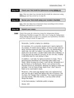
For paired bands, the spectrum will be in the 1920 – 1980 and 2110 – 2170 MHz ranges. For
the unpaired band, a total of 35 MHz will be allocated. A spectrum identification has been
made to identify the parts of the 2 GHz band for IMT-2000 operation.
IMT-2000 MSS IMT-2000 MSS
2000 2050 2100 2150 2200 22501950190018501800
MSS
reg.2
MSS reg.2
Frequency in MHz
Figure 1. ITU Spectrum Allocation
2.1 Significant Features of W-CDMA
The main features which make W-CDMA a promising air interface for 3G systems include:
1) improved performance over second-generation systems; improved capacity and
coverage,
2) flexible service implementation and support of multiplexing parallel services on a
single physical connection,
ETSI Wideband CDMA Standard for the UTRA FDD Air Interface
4
3) support of a wide range of services at up to 2 Mbps,
4) two packet data operation modes: dedicated and common channel packet operation,
5) fast, efficient packet access,
6) support of intra-frequency, inter-frequency, GSM-UTRA handoffs,
7) support for enhanced capabilities such as adaptive antenna arrays, multiuser
detection, and interference cancellation,
8) asynchronous base transceiver station (BTS) operation, and
9) fast transmit power control (TPC) in both directions.
The following table lists the key parameters of W-CDMA.
Multiple-access scheme DS-CDMA
Bandwidth 5 / 10 / 20 MHz
Chip rate 4.096 / 8.192 / 16.384 Mcps
Carrier spacing (4.096 Mcps) Flexible in the range 4.4 – 5.2 MHz (200 kHz carrier raster)
Roll-off factor 0.22
Frame length 10 ms (20 ms optional)
Inter-cell synchronization Asynchronous; no synchronization needed (synchronous also
possible)
Spreading modulation QPSK (downlink)
QPSK (uplink)
Data modulation QPSK (downlink)
BPSK (uplink)
Coherent detection User-dedicated time-multiplexed pilot (uplink and downlink),
Common pilot can also be used in downlink
Multirate Variable-spreading and multicode
Spreading factor (ratio of chip
rate over information rate)
4 – 256 (4.096 Mcps)
Channel coding Convolutional coding (R = 1/3 or 1/2, K = 9), Turbo code
Spreading Spreading code and Scrambling code
Spreading code (downlink) Variable-length orthogonal sequences for channel separation,
Gold sequences for cell and user separation
Spreading code (uplink) Variable-length orthogonal sequences for channel separation,
Gold sequence 2
41
for user separation
Packet access Dual mode (common and dedicated channel)
Handover Soft handover,
Interfrequency handover
Table 1. Key Parameters of W-CDMA
ETSI Wideband CDMA Standard for the UTRA FDD Air Interface
5
2.2 Performance Capabilities
Some of the technical benefits of W-CDMA which greatly enhance its performance include
the following:
2.2.1 Capacity
The wide bandwidth of W-CDMA offers an improvement in the performance over
previous cellular systems, since fading of the radio signal is reduced [9]. W-CDMA
RF transceivers can accommodate 8 times more voice users than narrowband
transceivers. Each RF carrier can handle 100 simultaneous voice calls, or 50
simultaneous data calls. The capacity of W-CDMA is about double that of
narrowband CDMA in urban and suburban environments [8]. An operator will be
able to accommodate at least 192 voice calls per sector, compared to about 100 voice
calls per sector for GSM. In addition, coherent demodulation on the uplink, which is
a feature not previously implemented in earlier cellular systems, combined with fast
power control on the downlink, hierarchical cell structuring, and adaptive antenna
arrays all improve performance and reduce receiver threshold, especially in indoor
and low-speed outdoor environments at low Doppler. Cumulatively, these factors
theoretically improve cell capacity by at least 3 dB (or a factor of 2).
2.2.2 Coverage and Link Budget
Coverage of W-CDMA is determined by the link performance through the link
budget. With W-CDMA, it is possible to reuse GSM1800 cell sites when moving
from the GSM to W-CDMA infrastructure, since the latter uses a similar network
protocol structure. W-CDMA voice service will tolerate a few dB higher path loss
than GSM. This means that W-CDMA gives better voice coverage than GSM when
reusing the same cell sites at the same frequency band.