effects of split injection, oxygen enriched air, and heavy egr rate on soot emissions in a diesel engine
Bạn đang xem bản rút gọn của tài liệu. Xem và tải ngay bản đầy đủ của tài liệu tại đây (2.31 MB, 117 trang )
Effects of Split Injection, Oxygen Enriched Air,
and Heavy EGR Rate on Soot Emissions
in a Diesel Engine
Nguyen Le Duy Khai
The Graduate School
Sungkyunkwan University
Department of Mechanical Engineering
Effects of Split Injection, Oxygen Enriched Air,
and Heavy EGR Rate on Soot Emissions
in a Diesel Engine
Nguyen Le Duy Khai
A Dissertation Submitted to the Department of Mechanical Engineering
and the Graduate School of Sungkyunkwan University
in partial fulfillment of the requirements
for the degree of Doctor of Philosophy
June 2009
Approved by
Professor Nakwon Sung
Major Advisor
Contents
List of Tables ii
List of Figures iii
Nomenclature viii
Chapter 1 Introduction 1
Chapter 2 Soot Model 6
Chapter 3 Results and Discussion
3.1 General results 25
3.2 Effects of split injection 42
3.3 Effects of oxygen enriched air (OEA) and split injection 57
3.4 Effects of heavy EGR, OEA, and split injection 78
Chapter 4 Conclusions 94
References 97
Abstract 106
- -
i
List of Tables
Table 1 Data for carbon. 14
Table 2 Rate of change of mass fraction of species. 20
Table 3 Engine specifications. 23
Table 4 Computational test conditions. 23
Table 5 Mass of species in the intake air. 79
- ii -
List of Figures
Figure 1 Schematic diagram of flame in diesel engine (Dec, 1995). 6
Figure 2 Schematic diagram of the soot model. 12
Figure 3 Saturation vapor pressure of carbon as function of temperature. 15
Figure 4 Comparison of net acetylene mass between Lee model and Fusco
model in case of single injection without EGR.
21
Figure 5 Comparison of net soot mass between Lee model and Fusco model
in case of single injection without EGR.
22
Figure 6 Schemes of split injection and single injection. 24
Figure 7 The computational meshes at 3
o
BTDC. 24
Figure 8 Comparison of calculated and measured cylinder pressure and heat
release rate in case of single injection without EGR.
26
Figure 9 Comparison of calculated and measured cylinder pressure in case of
split injection.
27
Figure 10 Comparison of soot and NOx emissions between calculation and
experiment of single injection with different injection timing.
28
Figure 11 Comparison of NOx and soot emissions with various amount of fuel
injected during the first pulse of split injection without EGR.
29
Figure 12 Distributions of temperature and soot on the cutting plane at
4
o
ATDC in case of single injection without EGR.
30
Figure 13 Variation in heat release rate. 31
- iii -
Figure 14 Variation in average gas temperature. 32
Figure 15 Variations in mass of precursor formation, conversion into soot
particles, oxidation, and net precursor.
33
Figure 16 Results at 10
o
ATDC. 34
Figure 17
Variation in gas mass fraction with φ = 1.2-2.0.
35
Figure 18 Variations in acetylene formation, oxidation, consumption, and net
acetylene.
36
Figure 19 Rate of acetylene formation, oxidation, and consumption at
10
o
ATDC.
37
Figure 20 Rate of acetylene formation, oxidation and consumption at
90
o
ATDC.
38
Figure 21 Distribution of acetylene and soot at 10
o
ATDC. 39
Figure 22 Variations in soot formation, soot oxidation and net soot. 40
Figure 23 Summarized diagram of soot production. 41
Figure 24 Comparison of heat release rate between single injection and split
injection.
42
Figure 25 Variation in average gas temperature. 43
Figure 26 Variation in precursor formation, conversion into soot, and
oxidation.
44
Figure 27 Variations in precursor formation rate. 45
Figure 28 Distribution of equivalence ratio, temperature and precursor
formation rate at 15
o
ATDC.
46
- iv -
Figure 29
Variations in rich mixture (φ = 1.2-2.0) mass fraction.
47
Figure 30 Variations in net precursor. 48
Figure 31 Variations in acetylene formation, oxidation and consumption. 49
Figure 32 Variations in net acetylene. 49
Figure 33 Variations in soot formation and oxidation. 50
Figure 34 Distributions of temperature and soot formation rate at 90
o
ATDC. 51
Figure 35 Reaction rate of soot oxidation at 20
o
, 50
o
and 90
o
ATDC. 52
Figure 36 Variations in net soot. 54
Figure 37 Variations in NOx. 54
Figure 38 Diesel emissions of various schemes. 55
Figure 39 Indicated power. 56
Figure 40 Variations in burned fuel. 57
Figure 41 Variations in average gas temperature. 58
Figure 42 Distribution of equivalence ratio, temperature, and precursor
formation rate at 10
o
ATDC.
59
Figure 43
Variations in rich mixture (φ = 1.2 - 2.0) mass fraction.
60
Figure 44 Variations in precursor formation, conversion into soot, and
oxidation.
61
Figure 45 Variations in net precursor. 61
Figure 46 Variations in acetylene formation, oxidation, and consumption. 62
Figure 47 Reaction rate of acetylene formation, oxidation, and consumption. 64
Figure 48 Reaction rate of acetylene consumption at 30
o
ATDC. 65
- v -
Figure 49 Variations in mass of net acetylene. 65
Figure 50 Variations in soot formation and oxidation. 66
Figure 51 Reaction rate of soot formation and soot oxidation at 90
o
ATDC. 67
Figure 52 Variations in net soot. 68
Figure 53 Variations in NOx. 68
Figure 54 Variations in average gas temperature. 69
Figure 55 Variations in burned fuel. 70
Figure 56 Variations in net precursor. 71
Figure 57 Variations in net acetylene. 72
Figure 58 Reaction rates of acetylene formation, oxidation, and growth with
soot.
74
Figure 59 Variations in soot formation and oxidation. 74
Figure 60 Distributions of soot formation rate and oxidation rate at 90
o
ATDC. 75
Figure 61 Variations in net soot. 76
Figure 62 Trend of diesel emissions with various oxygen concentrations. 77
Figure 63 Effect of EGR ratio on soot emissions in case of single injection. 78
Figure 64 Variations in temperature. 80
Figure 65 Variations in NOx. 81
Figure 66 Results at 10
o
ATDC. 82
Figure 67 Distributions of temperature at 20
o
ATDC. 83
Figure 68 Variations in rich-mixture mass percentage. 83
Figure 69 Variations in precursor formation and net precursor. 84
- vi -
Figure 70 Variations in acetylene formation, oxidation and consumption. 84
Figure 71 Variations in net acetylene. 86
Figure 72 Variations in reaction rate of acetylene formation and growth with
soot.
87
Figure 73 Variations in soot formation and oxidation. 88
Figure 74 Reaction rate of soot formation and oxidation at 90
o
ATDC. 89
Figure 75 Variations in net soot. 90
Figure 76 Variations in NOx. 91
Figure 77 Diesel emissions with different schemes. 91
Figure 78 Indicated power. 92
- vii -
Chapter 1 Introduction
In the past, diesel engines were used mainly in heavy duty trucks and buses, however
many passenger cars and SUVs have been changed over to diesel nowadays because
diesel engines offer more benefits than gasoline engines. Diesel engines are designed to
have higher compression ratio which gives them more torque. Another advantage of
diesel engines is lower fuel consumption. There is no doubt that diesel vehicles have
been gained more appreciation from consumers and the number of diesel vehicles will
be raised in the future. As the number of diesel engines increases, reducing their
emissions has become more important. Nitrogen oxides (NOx) and soot emissions in
diesel engines are the most challenging to reduce. Nitrogen oxides are efficiently
controlled in the combustion process by exhaust gas recirculation (EGR). However, a
decrease in NOx is usually accompanied by an increase in soot. An aftertreatment
device such as a diesel particulate filter is needed to control soot emissions, however
using this device requires additional cost, including equipment cost, operation cost, and
maintenance cost. A strategy to reduce NOx and soot simultaneously without after
treatment devices is necessary; for example, a combination of split injection with
oxygen enriched air (OEA) and EGR.
Split injection has been used as a method to reduce soot emissions in diesel engines.
In 1990, Schulte et al. [1] showed the possibility of applying split injection with an
electronic unit injector. Split injection became more practical later with the development
- 1 -
of a common rail injection system [2-4]. Many studies have been done to examine the
effects of split injection on engine emissions. By varying the amount of fuel in the first
injection, Nehmer and Reitz [5] found that soot emissions decrease when more fuel is
injected in the first
injection. Tow et al. [6] evaluated the effect of dwell period on diesel
emissions. They reported that a long dwell period is effective for significant reduction in
soot emissions. For example, when a 10
crank angle degree dwell is used in split
injection scheme 48.10.52, in which 48% fuel injected in the first pulse and 52% fuel
injected in the second pulse, soot emissions are reduced by a factor of three without
increase in NOx emissions. Han et al. [7] numerically studied a mechanism of reduction
of soot emissions of split injection and found that the optimum split injection scheme
was 75.8.25 in their study cases. With this scheme, soot emissions are reduced by a
factor of four while NOx emissions increase slightly in comparison with single injection.
Other researchers [8-10] using two-color imaging optics to observe the soot emission
process in diesel engines also confirmed the benefit of split injection in reducing soot
emissions. There is some reasons lead to the reduction of soot emissions with split
injection. Tow et al. [6] and Kong et al. [11] pointed that the second injection of fuel
enhances the fuel/air mixing and thus improves the oxidation of soot from the first
injection. Han et al. [7] showed that the second injected fuel is entered into a relatively
fuel-lean and high temperature region which is left over from the combustion of the first
injection. The fuel injected by the second injection is quickly burned, and thus it does
not contribute significantly to soot production. In general, split injection reduces soot
emissions, however, split injection can cause an increasing in soot emissions if the
injection timing is too retarded or the injection dwell is not optimized [8, 9].
- 2 -
The concept of using oxygen enriched air in diesel engines has been studied for years.
The use of OEA has advantages such as reduction of soot emissions, carbon monoxide
(CO), and unburned hydrocarbons [12-15]. However, the increase in NOx emissions
and lack of practical on-board oxygen enrichment devices prevented any applications of
this concept. In recent years, however, there has been progress in the development of
oxygen enrichment devices such as a permeable oxygen membrane [16, 17]. A compact
membrane module developed by Argonne National Laboratory can increase the
concentration of oxygen to 23-25% in volume and can be incorporated into a vehicle
design [16]. As this technology is developed, oxygen enriched air becomes more
attractive as a method to reduce soot emissions.
The effects of EGR on the reduction of NOx emissions in diesel engines have been
confirmed a long time ago, and it is an indispensable technology for modern diesel
engines. Because the EGR affects diesel combustion through the dilution of the inlet
charge air with carbon dioxide (CO
2
) and water vapor (H
2
O), the local flame
temperature is decreased, and thus NOx formation is decreased [18-23]. However, the
lower temperature results in increased soot emissions. To avoid this drawback, many
researchers suggested that EGR ratio should be restricted. Kim and Sung [23] showed in
their study that the optimum EGR ratio is 10% at the full load and 15% at the part load.
Wagner et al. [24] reported that soot emissions start to increase significantly at EGR
ratio of 30%, and a steep increase is observed once the EGR ratio reaches about 45%.
Uchida et al. [25] suggested the EGR ratio of 20% should be used, since at this ratio
NOx emissions are reduced by 50% without penalty of soot emissions. Whereas EGR
- 3 -
decreases NOx emissions and increases soot emissions, the OEA technology has reverse
effects. If EGR is used together with OEA, a higher EGR ratio can be applied to reduce
NOx emissions without a penalty on soot emissions.
It is of interest to examine the effects of a combination of these technologies on diesel
emissions. Taking the benefits of EGR for reducing NOx emissions and split injection
for reducing soot emissions, Pierpont et al. [26] examined the possibility of a combined
use of EGR and split injection. They reported that this combination is effective in
reducing both soot and NOx, especially during a high load (75%) when EGR causes a
significant increase in soot emissions. In the study of Montgomery and Reitz [27], NOx
and soot emissions as well as fuel consumption can be reduced over the entire engine
operating map with the use of multiple injection and EGR. They showed that at a 1600
rev/min and 75% load running condition, NOx and soot emissions could be further
reduced by using 10% EGR with a quadruple injection. Other researches confirmed that
NOx and soot emissions are reduced simultaneously with the combined use of split
injection and EGR [28-30] and they tried to optimize the operating parameters to
receive the full benefits of this combination [31-34].
In this study, a simulated method is applied to investigate the effects of the
combination of split injection, OEA, and EGR on soot emissions in a DI diesel engine.
The level of reduction of emissions is dependent on many variables: engine load,
injection pressure, injection timing, OEA concentration, EGR ratio and split injection
parameters such as the ratio of fuel injected in fist pulse to second pulse, the dwell angle,
and the profile of injected velocity. Due to the complexity of the problem, optimization
- 4 -
is not a main target of this study. The research presented herein focuses only on the
effects of each technology on the production of intermediate species during the
combustion process, and how these changes affect the final emissions. The purpose is to
understand the mechanism of soot formation and oxidation, to get details of spatial
distribution and time evolution of quantities which are relevant to soot production, and
to evaluate their influence on soot production during the combustion. At the beginning,
the split injection scheme of 75.8.25 is used with an EGR rate of 20%. Other schemes
such as 50.8.50 and 25.8.75 are also considered to evaluate the effect of different
injection schemes on diesel emissions. Then, a combination of split injection 75.8.25
with the oxygen concentration in the intake air increased to 22% in volume is tested.
After that, the concentration of oxygen is increased to 23% in volume to evaluate the
effects of higher oxygen concentration. Finally, a high OEA concentration of 23% with
a heavy EGR ratio of 30% and split injection is used, and the result is compared with
the previous tests.
- 5 -
Chapter 2 Soot Model
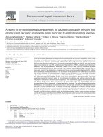
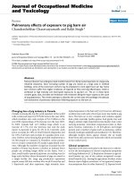
The formation of soot in a diesel engine has been studied for many years. In 1997,
Dec [35] presented a schematic diagram of flame in a diesel engine based on a series of
his previous experimental researches [36-38]. The diagram of Dec is shown in Figure 1.
It reveals the evolution of a diesel fuel jet from the start of injection until the end of
injection. It also gives a mechanism for soot formation, soot oxidation and a distribution
of soot in a diesel flame. Following Dec [35], soot appears throughout a jet cross-
section rather than only in the shell around the jet periphery as the old description.
Small soot particles are formed initially at the zone of fuel-rich premixed flame near the
tip of the liquid jet. After formation, these soot particles move downstream. During
Figure 1 Schematic diagram of flame in diesel engine (Dec, 1995).
- 6 -
movement, they grow in size and volume fraction, and the soot concentration reaches
the highest level at the head vortex. Soot particles also move outward, and they are
oxidized at the diffusion flame zone located around the jet periphery which has enough
oxygen and high temperature. The soot model of Dec [35] is verified successfully by
other researchers later [39, 40]. Although the experimental model of Dec [35] illustrates
the spatial distribution of soot quite well, it is limited within a short period of
combustion process, just from start of injection to end of injection.
Experimental methods are important but they are expensive to perform, and
sometimes are impossible. Whenever the operating conditions need to be changed to
explore their effects, a complicated system configuration needs to be set up. Moreover,
the observation of soot distribution in the burnout phase of combustion, which is from
the end of fuel injection to the end of combustion, is difficult because the soot
concentration becomes too low to be detected during this period, and the distribution of
soot particles may be shifted out of the field of view.
Another approach to study soot
emissions is a modeling method. The availability of a high performance computing
hardware nowadays makes modeling to be an essential analysis tool in engine research
and development. Modeling has an ability to study a system where experiments are
difficult or impossible to perform. In addition, modeling can explore unlimited level of
detail of results, and it reduces time and cost significantly. Modeling method is
especially convenient to perform parametric studies and optimal studies. In the literature,
a variety of soot models with different level of complexity were proposed and applied to
modeling of diesel combustion. Among them, the two-step soot model of Hiroyasu et al.
[41] and the eight-step soot model of Fusco et al. [42] are the most popular.
- 7 -
The two-step soot model of Hiroyasu et al.
[41] includes two reaction steps, one for
soot formation and one for soot oxidation. The rates of soot formation and soot
oxidation are expressed in Arrhenius form as shown in Eqs. (1) and (2). The net rate of
change in soot mass, Eq. (3), is the difference between the rates of soot formation and
soot oxidation,
0.5
exp
sf f
ffv
dm E
Am P
dt RT
⎛⎞
=−
⎜⎟
⎝⎠
(1)
1.8
2
exp
so o
osO
dm E
AmX P
dt RT
⎛
=
⎜
⎝⎠
⎞
−
⎟
(2)
sf
s
so
dm
dm dm
dt dt dt
=−
. (3)
In the above equations,
s
f
m ,
s
o
m , and
s
m are the formed, oxidized, and the net soot
mass respectively,
f
v
m
is the fuel vapor mass, is the pressure in bar, and P
2O
X
is the
mole fraction of oxygen. Hiroyasu et al. [41] suggested the activation energies of 12500
cal/mole for
f
E and 14000 cal/mole for . The pre-exponential factors,
o
E
f
A and ,
are adjustable to match the corresponding measured data of soot emissions for each
experimental case.
o
A
In 1994, Patterson et al. [43] pointed out that the Hiroyasu model gives a relatively
low peak of soot concentration in a cylinder. They modified the Hiroyasu soot model by
replacing the soot oxidation reaction by the Nagle and Strickland-Constable (NSC) soot
- 8 -
oxidation model
[44]. In the NSC model, soot oxidation occurs by two mechanisms
involving the more reactive type A sites and the less reactive type B sites on the soot
surface. The reaction rate is given by Eq. (4),
()
2
2
2
1
1
AO
total A B O A
ZO
kP
R
xkP x
kP
=+
+
− (4)
where
is the partial pressure of oxygen, and
2O
P
A
x
is the fraction of the surface
occupied by type A sites,
1
2
1
T
A
BO
k
x
kP
−
⎛⎞
=+
⎜⎟
⎝⎠
. (5)
The rate constants,
A
k , , , and
B
k
T
k
Z
k , are
15100
20exp
A
k
T
⎛⎞
=−
⎜⎟
⎝⎠
(6)
()
3
7640
4.46 10 exp
B
k
T
−
⎛⎞
=× −
⎜⎟
⎝⎠
(7)
()
5
48800
1.51 10 exp
T
k
T
⎛⎞
=× −
⎜⎟
⎝⎠
(8)
2060
21.3exp
Z
k
T
⎛
=
⎜
⎝⎠
⎞
⎟
. (9)
- 9 -
The rate of soot mass oxidation is
6
so C
s
total
sp
dm MW
mR
dt d
ρ
=
(10)
where
C
M
W is the carbon molecular weight,
s
ρ
is the soot density, and is the soot
diameter. Due to the simplicity and computational efficiency, the two-step soot model
of Hiroyasu and its modified versions are used commonly in diesel engine simulations
[7, 8, 22, 23, 28, 32, 33, 45, 46]. One of its drawbacks is that the Hiroyasu soot model
cannot be applied reliably to other systems except those for which it was calibrated.
Moreover, it cannot provide detail information regarding the soot formation process in a
cylinder.
p
d
In 1994, Fusco et al. [42] proposed an eight-step phenomenological soot model. In
their model, the soot production does not link directly to fuel but through two
intermediate species, precursor and acetylene. Soot is formed through a series of
processes such as fuel pyrolysis to precursor and acetylene, particle inception, surface
growth of particles with acetylene, soot coagulation and soot oxidation. In 1998,
Kazakov and Foster [47] modified the Fusco’s model. They counted the effect of
turbulent mixing on oxidation process by using the harmonic mean of the kinetic
oxidation rate and the mixing oxidation rates for the final oxidation rates of precursor,
acetylene and soot particles. Because the eight-step model of Fusco offers a better
physical description of soot formation and it shares similar advantages of the two-step
- 10 -
model of Hiroyasu, the Fusco soot model and its modified version have been developed
and applied widely in simulation of diesel combustion recently [48-52].
In this study, the soot model of Kazakov and Foster [47] is modified and is used to
simulate the soot production. The computation is performed by the modified version of
KIVA-3V code [53], which was developed at Los Alamos National Laboratory, USA.
The turbulent flows are modeled using the Renormalization Group (RNG) k-ε
turbulence model proposed by Han and Reitz [54]. The spray model is a wave breakup
model developed by Reitz [55]. In this spray model, the breakup mechanisms of
Rayleigh-Taylor and Kelvin-Helmoltz instabilities are implemented. Diesel combustion
modeling is divided into two regimes: ignition and combustion. The ignition process is
modeled using the Shell model developed by Halstead and Quinn [56] for low
temperature chemistry. If the cell temperature reaches the specified temperature (was set
at 1100K), the laminar and turbulent characteristic time combustion model of Kong et al.
[45] is activated for describing high temperature chemistry. The extended Zeldovich
mechanism described by Heywood [57] is implemented for calculating NOx formation.
The multi-step Foster soot model [47] is used to calculate soot formation, and the NSC
model [44] is used to calculate soot oxidation.
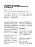
A schematic diagram of the eight-step soot model of Foster is shown in Figure 2.
Under high temperature during combustion, precursor and acetylene are generated
simultaneously from fuel pyrolysis. For calculation, the precursor, , is assumed to be
C
PR
50
, and the fuel is n-tetradecane (C
14
H
30
) due to its similar carbon/hydrogen ratio to
diesel fuel. The global chemical reactions are as follows:
- 11 -
Figure 2 Schematic diagram of the soot model.
C
14
H
30
Æ 0.28 PR + 15H
2
(11)
C
14
H
30
Æ 7C
2
H
2
+ 8H
2
(12)
and their reaction rates are
12
1
120
0.7 10 *exp
F
r
RT
⎛⎞
=× −
⎜⎟
⎝⎠
Y
(13)
8
2
49
0.9 10 *exp
F
r
RT
⎛⎞
=× −
⎜⎟
⎝⎠
Y
. (14)
- 12 -
A portion of precursors was converted into soot particles,
PR
Æ 50C
soot
. (15)
In this study, the solidification of carbon molecules presented by Lee et al. [58] is used
for the inception of soot particles instead of the chemical reaction suggested in the
Foster model. After formation, the partial pressure of precursors in the product increases
gradually. When the partial pressure of gaseous precursors in the mixture exceeds the
saturation pressure of carbon,
, at the given temperature, T , the phase change of
gaseous precursors into solid particles is occurred. The saturation pressure of carbon is
obtained by applying the Clapeyron relation,
SAT
P
2
IG
dP h dT
PRT
=
. (16)
The necessary data for calculation
SAT
P
are listed in Table 1. Integrating the Clapeyron
equation between the triple point,
TP , and the state of product, the saturation pressure
of carbon is found,
11
exp
IG
SAT TP
TP
h
PP
R
TT
⎡⎤
⎛⎞
=−
⎢⎥
⎜⎟
⎝⎠
⎣⎦
. (17)
The pressure at triple point, , is calculated via the pressure at normal boiling point,
TP
P
- 13 -
Table 1 Data for carbon.
Parameter Value
Enthalpy of fusion, h
IF
104.6 (kJ/kg)
Enthalpy of vaporization, h
FG
355.8 (kJ/kg)
Normal melting point, T
NMP
3773 (K)
Normal boiling point, T
NBP
5000 (K)
NBP
P , and temperature at normal boiling point,
NBP
T
,
11
exp
IG
TP NBP
NBP TP
h
PP
RT T
⎡⎤
⎛⎞
=−
⎢⎥
⎜⎟
⎝⎠
⎣⎦
. (18)
The temperature at triple point,
, is assumed to be the temperature at normal melting
point,
. The calculation results in the pressure – temperature diagram which is
shown in Figure 3. The mass fraction of gaseous precursors is
TP
T
NMP
T
SAT PR
SAT
mixture
PMW
Y
PMW
= . (19)
The rate of change of precursors is
PR PR SAT
INC
dY Y Y
dt t
−
=−
∆
. (20)
- 14 -
Figure 3 Saturation vapor pressure of carbon as function of temperature.
The reaction rate of the inception of soot particles from precursors is
3
s
oot PR SAT
INC
dY Y Y
r
dt t
−
==
∆
. (21)
Acetylene adds carbon atoms to the surface of soot particles,
C
soot
+ C
2
H
2
Æ C
soot+2
+ H
2
(22)
The rate of growth reaction of acetylene with soot particle,
, is adopted following
Leung et al. [59],
4
r
- 15 -
4
4
12
4.2 10 *exp
F
r
RT
⎛⎞
=× −
⎜⎟
⎝⎠
1/2
YS
. (23)
Leung et al. [59] suggested that the growth rate being proportional to
provides a
better result as compared to the traditional expression proportional to
. The total soot
surface area per unit volume,
, is calculated from
1/2
S
S
S
2
p
SdN
π
= (24)
and the soot particle diameter,
, is calculated by
p
d
1/3
6
s
p
s
Y
d
N
ρ
πρ
⎛⎞
=
⎜⎟
⎝⎠
(25)
where
is the soot particle number density,
N
ρ
is the mixture density, and
s
ρ
is the
soot density.
Soot particles also coagulate together to form bigger soot particles,
nC
soot
Æ C
soot
. (26)
The rate of coagulation is given by
2
5
0.5rN
β
= . (27)
- 16 -