catalytic modification of flammable atmosphere in aircraft fuel tanks
Bạn đang xem bản rút gọn của tài liệu. Xem và tải ngay bản đầy đủ của tài liệu tại đây (23.18 MB, 51 trang )
Catalytic Modification of Flammable Atmosphere in Aircraft
Fuel Tanks
Thesis by
Inki Choi
In Partial Fulfillment of the Requirements
for the
Engineer’s Degree
California Institute of Technology
Pasadena, California
2010
(Submitted June 7, 2010)
ii
c
2010
Inki Choi
All Rights Reserved
iii
Acknowledgments
I would like to show my appreciation to my academic advisor Professor Joseph Shepherd. He advised
me with his abundant experience and knowledge to overcome obstacles whenever I lost my way. His
patience especially allowed me to learn lots of experimental knowledge and gave me a scientific
attitude.
My thesis committee members, Professors Meiron and Blanquart gave me very instructive com-
ments. Their comments were of great help for me to complete a more integrated thesis.
I am also thankful to my laboratory members. They kept helping me adapt myself to life at
Caltech. I appreciate particularly Philipp Boettcher and Sally Bane who helped me in various ways
to fulfill my goal with experimental experiences and techniques.
Finally, I really want to show my deepest thanks to my wife who assisted me sincerely throughout
the years here at Caltech. She was strong and very supportive even though it was very difficult time
for us to stay here.
The work was carried out in the Explosion Dynamics Laboratory of the California Institute
of Technology and was supported by the Boeing Company through the Strategic Research and
Development Relationship agreement CT-BA-GTA-1.
I would like to thank Ivana Jojic, Leora Peltz, and Shawn Park at the Boeing Company, and Prof.
Sossina Haile, Sinchul Yeom, Taesik Oh, Steve Ballard, Richard Gerhart, and Thomas Brennan for
making this experiment possible.
iv
Abstract
A facility for investigating catalytic combustion and measurement of fuel molecule concentration
was built to examine catalyst candidates for inerting systems in aircraft. The facility consists of
fuel and oxygen supplies, a catalytic-bed reactor, heating system, and laser-based diagnostics. Two
supplementary systems consisting of a calibration test cell and a nitrogen-purged glove box were also
constructed. The catalyst under investigation was platinum, and it was mixed with silica particles
to increase the surface area available to react. The catalyst/silica mixture was placed in a narrow
channel section of the reactor and supported from both sides by glass wool. The fuels investigated
were n-octane and n-nonane because their vapor pressure is sufficiently high to create flammable
gaseous mixtures with atmospheric air at room temperature. Calibration experiments were per-
formed to determine the absorption cross-section of the two fuels as a function of temperature. The
cross-section values were then used to determine the fuel concentration before the flow entered the
reactor and after exposure to the heated catalyst. An initial set of experiments was performed with
the catalytic-bed reactor at two temperatures, 255 and 500
◦
C, to investigate pyrolysis and oxidation
of the fuel. The presence of the catalyst increased the degree of pyrolysis and oxidation at both
temperatures. The results show that catalytic modification of flammable atmospheres may yield a
viable alternative for inerting aircraft fuel tanks. However, further tests are required to produce
oxidation at sufficiently low temperature to comply with aircraft safety regulations.
v
Contents
Abstract iv
1 Introduction 1
1.1 Background . . . . . . . . . . . . . . . . . . . . . . . . . . . . . . . . . . . . . . . . . 1
1.2 Objective . . . . . . . . . . . . . . . . . . . . . . . . . . . . . . . . . . . . . . . . . . 3
2 Theory 4
2.1 Catalytic Combustion . . . . . . . . . . . . . . . . . . . . . . . . . . . . . . . . . . . 4
2.2 Types of Catalysts . . . . . . . . . . . . . . . . . . . . . . . . . . . . . . . . . . . . . 5
2.3 Ceramic Supporter . . . . . . . . . . . . . . . . . . . . . . . . . . . . . . . . . . . . . 5
2.4 Catalyst Geometry . . . . . . . . . . . . . . . . . . . . . . . . . . . . . . . . . . . . . 5
2.5 Laser Diagnostics . . . . . . . . . . . . . . . . . . . . . . . . . . . . . . . . . . . . . . 6
3 Experimental Setup 7
3.1 Piping System . . . . . . . . . . . . . . . . . . . . . . . . . . . . . . . . . . . . . . . 7
3.2 Gaseous Fuel Generating System . . . . . . . . . . . . . . . . . . . . . . . . . . . . . 8
3.3 Heating System . . . . . . . . . . . . . . . . . . . . . . . . . . . . . . . . . . . . . . . 10
3.3.1 Pipe Heating System . . . . . . . . . . . . . . . . . . . . . . . . . . . . . . . . 10
3.3.2 Flange Heating System . . . . . . . . . . . . . . . . . . . . . . . . . . . . . . 11
3.4 Catalyst-Packed Reactor . . . . . . . . . . . . . . . . . . . . . . . . . . . . . . . . . . 13
3.5 Laser Diagnostics . . . . . . . . . . . . . . . . . . . . . . . . . . . . . . . . . . . . . . 15
3.6 Auxiliary Systems . . . . . . . . . . . . . . . . . . . . . . . . . . . . . . . . . . . . . 18
3.6.1 Calibration System . . . . . . . . . . . . . . . . . . . . . . . . . . . . . . . . . 18
3.6.2 Glove Box . . . . . . . . . . . . . . . . . . . . . . . . . . . . . . . . . . . . . . 18
4 Experimental Procedures 20
4.1 Catalyst Preparation . . . . . . . . . . . . . . . . . . . . . . . . . . . . . . . . . . . . 20
4.2 Catalyst Packing . . . . . . . . . . . . . . . . . . . . . . . . . . . . . . . . . . . . . . 20
4.3 Calibration . . . . . . . . . . . . . . . . . . . . . . . . . . . . . . . . . . . . . . . . . 21
vi
4.4 Catalytic Modification . . . . . . . . . . . . . . . . . . . . . . . . . . . . . . . . . . . 22
4.5 Test Procedure . . . . . . . . . . . . . . . . . . . . . . . . . . . . . . . . . . . . . . . 22
5 Results and Discussion 26
5.1 Calibration . . . . . . . . . . . . . . . . . . . . . . . . . . . . . . . . . . . . . . . . . 26
5.2 Catalytic Modification . . . . . . . . . . . . . . . . . . . . . . . . . . . . . . . . . . . 27
5.2.1 Effect of Packing the Reactor on the Flow Rate . . . . . . . . . . . . . . . . . 28
5.3 Empty Reactor with n-Nonane . . . . . . . . . . . . . . . . . . . . . . . . . . . . . . 28
5.3.1 Reactor Filled with Glass Wool . . . . . . . . . . . . . . . . . . . . . . . . . . 29
5.3.2 Reactor Filled with Glass Wool and Silica . . . . . . . . . . . . . . . . . . . . 30
5.3.3 Reactor Filled with Glass Wool, Silica, and a Platinum Catalyst . . . . . . . 31
6 Conclusions 33
Bibliography 35
A Cross-Section Measurements 36
B Heat Transfer Calculations 37
C Experiment Checklist 39
vii
List of Figures
1.1 Catalytic modification of the flammable atmosphere in the aircraft fuel tank . . . . . 2
3.1 Schematic diagram of the experimental setup . . . . . . . . . . . . . . . . . . . . . . . 7
3.2 The mass flow controllers connected to the piping system . . . . . . . . . . . . . . . . 8
3.3 Gas exhaust fan and exhaust lines and condensed fuel removal system in the exhaust line 9
3.4 The fuel vessel, with stirring bar, and bubbler setup for creating fuel-air mixtures . . 9
3.5 Gaseous fuel generation system . . . . . . . . . . . . . . . . . . . . . . . . . . . . . . . 10
3.6 Control panel for the pipe heating system . . . . . . . . . . . . . . . . . . . . . . . . . 10
3.7 Circuit diagrams for the piping heating system . . . . . . . . . . . . . . . . . . . . . . 12
3.8 Heating and insulation system for the gas piping system . . . . . . . . . . . . . . . . . 13
3.9 Control panel for the flange heating system . . . . . . . . . . . . . . . . . . . . . . . . 13
3.10 Circuit diagrams for the flange heating system . . . . . . . . . . . . . . . . . . . . . . 14
3.11 Heating and insulation system for the reactor flanges . . . . . . . . . . . . . . . . . . . 14
3.12 Reactor assembly . . . . . . . . . . . . . . . . . . . . . . . . . . . . . . . . . . . . . . . 15
3.13 Catalytic bed . . . . . . . . . . . . . . . . . . . . . . . . . . . . . . . . . . . . . . . . . 15
3.14 Optical system for laser-based fuel sensing . . . . . . . . . . . . . . . . . . . . . . . . . 16
3.15 Schematic view of the optical setup . . . . . . . . . . . . . . . . . . . . . . . . . . . . 16
3.16 Screen shot of the LabVIEW virtual instrument used for fuel concentration measurements 17
3.17 Infrared filter . . . . . . . . . . . . . . . . . . . . . . . . . . . . . . . . . . . . . . . . . 17
3.18 Calibration system . . . . . . . . . . . . . . . . . . . . . . . . . . . . . . . . . . . . . . 18
3.19 Glove box used when handling the catalyst . . . . . . . . . . . . . . . . . . . . . . . . 19
3.20 Catalyst packing system . . . . . . . . . . . . . . . . . . . . . . . . . . . . . . . . . . . 19
4.1 Initial catalyst mixture preparation . . . . . . . . . . . . . . . . . . . . . . . . . . . . 21
4.2 Final catalyst mixture preparation and the mixture under the microscope . . . . . . . 23
4.3 Catalyst packing procedures and enlarged narrow section filled with mixture . . . . . 24
4.4 Logarithmic plot of the intensity ratio versus fuel concentration, with the slope equal
to the absorption cross-section . . . . . . . . . . . . . . . . . . . . . . . . . . . . . . . 25
5.1 Cross-section of n-octane as a function of temperature. . . . . . . . . . . . . . . . . . 27
viii
5.2 Cross-section of n-nonane as a function of temperature. . . . . . . . . . . . . . . . . . 27
5.3 Variation of fuel molar density and temperature at the inlet and outlet flanges for
n-nonane in the empty reactor . . . . . . . . . . . . . . . . . . . . . . . . . . . . . . . 29
5.4 Variation of fuel molar density and temperature at the inlet and outlet flanges for
n-nonane in the reactor filled with glass wool . . . . . . . . . . . . . . . . . . . . . . . 30
5.5 Variation of fuel molar density and temperature at the inlet and outlet flanges for
n-nonane in the reactor filled with glass wool and silica . . . . . . . . . . . . . . . . . 31
5.6 Variation of fuel molar density and temperature at the inlet and outlet flanges for
n-nonane in the reactor filled with glass wool, silica, and the platinum (Pt) catalyst . 32
B.1 Reactor schematic for heat transfer calculations . . . . . . . . . . . . . . . . . . . . . . 37
ix
List of Tables
2.1 Definitions and units of symbols in Equation 2.3 . . . . . . . . . . . . . . . . . . . . . 6
A.1 Cross section measurement of each fuel at selected temperatures . . . . . . . . . . . . 36
B.1 Heat transfer calculation variables . . . . . . . . . . . . . . . . . . . . . . . . . . . . . 38
B.2 Calculated temperature distribution . . . . . . . . . . . . . . . . . . . . . . . . . . . . 38
1
Chapter 1
Introduction
1.1 Background
A major concern in aviation safety and aircraft design is the possibility of accidental ignition of
flammable mixtures. This explosion risk can be mitigated by eliminating all sources of ignition,
which may be practically impossible, or by ensuring that the mixture composition cannot be ignited
by any source. The gas in the fuel tank ullage is one of the main concerns. For example, the National
Transport Safety Board investigation pointed out that the explosion of the center wing fuel tank
resulting from the ignition of the flammable atmosphere in the tank was the probable cause of the
TWA Flight 800 accident in 1996 (NTSB, 2000). Currently, the installation of an inert atmosphere
generation system on the fuel tank is required by the Federal Aviation Administration (FAA, 2008).
One inerting system currently in use is a hollow fiber membrane, which operates on the principle
of selective permeability creating an output flow that is highly enriched with nitrogen (Air Weekly,
2010). The output stream is directed into the fuel tank, displacing the potentially flammable mixture
in the fuel tank ullage and thereby lowering the oxygen concentration below the flammability limit.
A single unit of the hollow fiber membrane system weighs approximately 400 lbs and requires either
engine bleed air or a separate compressor for the high-pressure input into the bundle of membrane
fibers (Air Weekly, 2010). The use of engine bleed air requires a heat exchanger and ductwork
carrying air from the engine to the separation unit. These requirements stand in contrast to the
goal in current aircraft design, which aims to reduce weight and complexity by eliminating heat
exchangers and duct work by using electrical systems instead of bleed air. Hence, alternative methods
for inerting fuel tanks are in development.
One such alternative is low-temperature catalytic oxidation, which converts the flammable fuel-
air mixtures into inert products. The key idea is to use catalysts to initiate reactions between
hydrocarbon and oxygen molecules producing carbon dioxide and water vapor, which are fed back
into the fuel tank displacing the vapor in the ullage. In this manner, the overall composition in the
fuel tank is moved outside the flammability region, which is a function of the relative proportions of
2
fuel, oxygen, and the inert gas such as nitrogen or carbon dioxide (Zabetakis, 1965). The range of
flammable mixtures is in fact smaller when carbon dioxide is used as the diluent instead of nitrogen.
The proposed catalytic reaction combines the effect of lowering the oxygen concentration with the
flammability reducing effect of carbon dioxide over nitrogen.
A schematic diagram of a fuel tank with the catalytic reactor is shown in Figure 1.1a. The
pressure in the fuel tank is equal to the ambient pressure outside the plane at all times. The
proposed catalytic conversion system would be installed on the aircraft connected to the fuel tanks
via supply and return lines, such that flammable gas is removed from the fuel tank ullage and
replaced by the process products.
Figure 1.1b illustrates the process of initial inerting and composition changes for a typical flight
on a standard flammability diagram (Zabetakis, 1965). Immediately after fueling the plane the
composition may be flammable and the inerting system is turned on. The amount of diluent is
increased by the catalytic conversion, which corresponds to changing the composition from the
initial point to point A in Figure 1.1b. The concentration of fuel in the vapor is only a function of
the temperature and overall pressure because the fuel consumed in the reaction is replenished from
the liquid phase. During the climb to cruise altitude it is assumed that a homogeneous mixture of the
gas in the ullage is vented so that the concentration of fuel is increased and diluent gas concentration
is decreased, as shown by point B. At this point the gas should still be non-flammable in the fuel
tank ullage. However, as the plane descends and pressure increases the mixture may return into the
flammable region before which the catalytic modification system can be re-engaged and inert the
fuel tank.
3
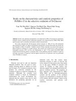
installed to deliver the flammable gas from the fuel tank to the reactor and back to the
tank. The flammable gas will be pulled out from the tank and modified into non-
flammable condition through the reactor. Then, it will return to the tank.
Figure 1-(b) is illustrating the possible courses to be used for the fuel modification in a
series of status of aircraft; takeoff, flight and landing. Firstly, the ullage gas in the tank
may be in the flammable region at the ground before takeoff as shown as a starting point.
The gas moves to point A in non-flammable region with increased diluent gas
concentration such as CO
2
by going through the catalytic reactor. The fuel concentration
does not change because the vapor pressure of the fuel is constant under the fixed
ambient pressure at an altitude. When an aircraft is gaining altitude, the concentrations of
fuel and diluent gas are reducing because of the decreasing of the atmospheric pressure.
Therefore, the status of ullage gas moves to point B. As the aircraft goes down to the
ground for landing, the increasing of the ambient pressure forces the ullage gas to move
to point C. This gas should be modified again through the reactor because it is in the
flammable region. By reducing the fuel concentrations through the reactor, the ullage gas
can come to the arriving point finally which is out of flammable region. In this point,
fuel concentration is the same as that of the starting point because they are both at the
same altitude; the ground level.
Fig. 1. Catalytic modification of flammable atmosphere in the aircraft fuel tank
(b) Flammable region and the plan to
treat the ullage gas in the tank
(a) Schematic diagram of the system
with the fuel tank & the fuel modifying
reacto
r
(a) Schematic diagram of the system
with the fuel tank and the catalytic re-
actor
3
installed to deliver the flammable gas from the fuel tank to the reactor and back to the
tank. The flammable gas will be pulled out from the tank and modified into non-
flammable condition through the reactor. Then, it will return to the tank.
Figure 1-(b) is illustrating the possible courses to be used for the fuel modification in a
series of status of aircraft; takeoff, flight and landing. Firstly, the ullage gas in the tank
may be in the flammable region at the ground before takeoff as shown as a starting point.
The gas moves to point A in non-flammable region with increased diluent gas
concentration such as CO
2
by going through the catalytic reactor. The fuel concentration
does not change because the vapor pressure of the fuel is constant under the fixed
ambient pressure at an altitude. When an aircraft is gaining altitude, the concentrations of
fuel and diluent gas are reducing because of the decreasing of the atmospheric pressure.
Therefore, the status of ullage gas moves to point B. As the aircraft goes down to the
ground for landing, the increasing of the ambient pressure forces the ullage gas to move
to point C. This gas should be modified again through the reactor because it is in the
flammable region. By reducing the fuel concentrations through the reactor, the ullage gas
can come to the arriving point finally which is out of flammable region. In this point,
fuel concentration is the same as that of the starting point because they are both at the
same altitude; the ground level.
Fig. 1. Catalytic modification of flammable atmosphere in the aircraft fuel tank
(b) Flammable region and the plan to
treat the ullage gas in the tank
(a) Schematic diagram of the system
with the fuel tank & the fuel modifying
reacto
r
(b) Flammable region and the plan to
treat the ullage gas in the tank
Figure 1.1: . Catalytic modification of flammable atmosphere in the aircraft fuel tank
3
Catalytic oxidation provides reaction pathways with lower energy barriers than conventional
oxidation processes in flames. Thus, the temperature at which the oxidation takes place is signif-
icantly lower than flame temperatures, which is are typically on the order of 2000
◦
C (Heyes and
Kolaczkowski, 1997). This technique is therefore potentially safer for use on aircraft in the fuel tank
ullage or flammable leakage zones.
1.2 Objective
The main objective of this study is to develop an evaluation methodology and test metrics for screen-
ing catalysts that can be used for low temperature oxidation of jet fuel. The initial investigation was
performed using a platinum catalyst in the laboratory using a bench-top experimental facility. The
facility consists of precisely controlled fuel and oxygen supplies, a once-through catalytic bed reactor,
a heated piping system, and laser-based diagnostics for measuring fuel concentration upstream and
downstream of the reactor. Auxiliary systems include a calibration test cell and nitrogen-purged
glove box for handling the catalyst.
4
Chapter 2
Theory
2.1 Catalytic Combustion
Catalytic combustion has been widely studied to understand the effect of the catalyst on the chemical
pathways in the reactions. The catalyst promotes reaction pathways with lower energy barriers so
that the fuel is burned at lower temperatures than in conventional combustion. Therefore, catalytic
combustion is less hazardous because the system as a whole operates at significantly lower temper-
atures than in flames. Also, catalytic combustion can be achieved in fuel-oxidizer mixtures outside
of the traditional flammability limits and can readily be studied in small-scale facilities (Heyes and
Kolaczkowski, 1997).
The major products of catalytic combustion, referred to as total oxidation, are carbon dioxide
and water vapor. Energy is released in the form of heat through the following overall reaction:
2C
𝑥
H
𝑦
+ (2𝑥 + 𝑦/2) O
2
→ 2𝑥CO
2
+ 𝑦H
2
O (2.1)
Due to the fact that the reactions occur at low temperatures, catalytic combustion produces less
nitrogen oxides than traditional combustion (Heyes and Kolaczkowski, 1997). Therefore, catalytic
combustion is a potential way to meet the increasingly strict emission regulations on industry and
transportation. The performance of catalytic combustors depends on many parameters such as
substrate structures, fuel-air ratio, catalytic material, and operating temperature.
Another reason that catalytic combustion is widely studied is that it provides a potential means
of producing hydrogen for use as a fuel or in fuel cell systems. Hydrogen is produced through the
partial oxidation reaction:
2C
𝑥
H
𝑦
+ 𝑥O
2
→ 2𝑥CO
2
+ 𝑦H
2
(2.2)
Fuel molecules can decompose through a process called pyrolysis, in which compounds undergo
reactions without oxygen that only occur at high temperatures. The initial compound is transformed
5
into smaller molecules in these reactions (Moldoveanu, 1998). Pyrolytic reaction can be promoted
by adding catalysts in what is called pyrolytic catalysis (Vasilieva et al., 1991).
Many previous studies on catalytic combustion have used methane as the fuel because methane
has been widely used in transportation and power generation. Additional interest in catalytic com-
bustion of methane has been prompted by its use in natural gas vehicles. Unburned methane in the
exhaust gases poses an explosion hazard and may contribute to the greenhouse effect (Gelin and
Primet, 2002).
2.2 Types of Catalysts
The noble metal catalysts, called the platinum group metals, have received attention for their high
activity, excellent thermal stability, and lower tendency to react with support materials in comparison
to base metals such as nickel (Ni), copper (Cu), cobalt (Co), manganese (Mn), and copper/chromium
(Cu/Cr) (Gandhi et al., 2003). Noble metals outperform base metals in aspects of catalytic com-
bustion such as intrinsic reactivity, durability, and poison resistance (Gandhi et al., 2003). In the
platinum group metals, platinum (Pt), palladium (Pd), and rhodium (Rh) are preferred because
ruthenium (Ru), iridium (Ir) and osmium (Os) all form volatile oxides which are impurities that
have to be removed in a secondary process (Gandhi et al., 2003).
2.3 Ceramic Supporter
The enhancement of catalytic reaction by ceramic particles has been reported in previous studies
[8, 9]. For methane combustion using Rh-based catalysts, the catalyst is most reactive when sup-
ported by aluminum oxide (Al
2
O
3
) and least reactive when supported by silicon dioxide (SiO
2
),
with titanium dioxide (TiO
2
) being an intermediate ceramic. In addition to enhancing the reactiv-
ity, ceramics can also be used as a structural support. The ceramic provides a surface for spreading
out the catalyst and thus increasing the surface area for reaction. Also, the ceramic particles can
be mixed and packed together with smaller catalyst particles to allow more porosity for the fuel-air
mixture to flow through.
2.4 Catalyst Geometry
There are geometric criteria that can be applied to a catalytic bed to increase its effectiveness. In
this study, a once-through cylindrical catalytic bed is considered, where 𝐷
𝑇
is the cylinder diameter,
𝐿 is the cylinder length, and 𝐷
𝑃
is the catalyst particle diameter. The first criterion that must be
met is 𝐷
𝑇
/𝐷
𝑃
> 10 to reduce the effect of channeling (Heyes and Kolaczkowski, 1997). Channeling
6
occurs when the majority of the flow travels through the single largest void in the packed catalyst
bed. The second criterion is that 𝐷
𝑇
should be as small as possible to ensure uniform temperature
while still maintaining an acceptable flow rate. As a compromise between the two criteria, the
following geometry limitations are applied to the setup: 6 < 𝐷
𝑇
/𝐷
𝑃
< 10 and 50 < 𝐿/𝐷
𝑃
< 100
to reduce the effect of axial dispersion.
2.5 Laser Diagnostics
Laser diagnostics are often used in combustion research because they are non intrusive and provide
fast response times to variations of species concentration. For example, laser absorption methods
can be used to obtain the concentration of a hydrocarbon fuel. A helium-neon (He-Ne) laser omits
light at a wavelength of 3.39 𝜇m, which corresponds to the resonance wavelength of the C-H bond
in a hydrocarbon molecule. Therefore, if the light from the He-Ne laser is passed through a gaseous
medium containing hydrocarbon molecules, some fraction of the light will be absorbed by the C-H
bonds and the intensity of the light will be reduced. The ratio of the observed light intensity, 𝐼, to
the intensity without any fuel present, 𝐼
0
, is related to the fuel concentration by Beer’s law:
𝐼
𝐼
0
= exp
(
−
𝜎
𝜈
𝑃 𝐿
˜
𝑅𝑇
)
= exp
(
−
𝜎
𝜈
𝑛𝐿
𝑉
)
(2.3)
The symbols in Equation 2.3 are defined in Table 2.1. If the value of the absorption coefficient,
𝜎
𝜈
, is known, then the mole density of the fuel, 𝑛/𝑉 , can be determined from the intensity ratio.
The absorption coefficient varies depending on the type of fuel, temperature, and pressure.
Table 2.1: Definitions and units of symbols in Equation 2.3
Parameter Units Description
𝐼 AU laser intensity
𝐿 m path length
𝑛 mol number of moles
𝑃 atm partial pressure
˜
𝑅 atm m
3
mol
−1
K
−1
universal gas constant
𝑇 K temperature
𝑉 m
3
volume
7
Chapter 3
Experimental Setup
The experimental setup consists of 5 sub-systems and 2 auxiliary systems. Sub-systems include a
piping system to deliver the gases, the pipe and flange heating systems, the gaseous fuel generating
system, the catalyst-packed reactor inside a furnace, and the laser diagnostic system to measure fuel
concentration upstream and downstream of the reactor. A calibration system and nitrogen-purged
glove box were added as auxiliary systems. A schematic diagram of the setup is shown in Figure 3.1.
!
Figure 3.1: Schematic diagram of the experimental setup
3.1 Piping System
The piping system has two functions: supplying a gaseous fuel-air mixture to the reactor and
venting the exhaust out from the setup. The amounts of nitrogen and air supplied to the reactor
are controlled by two mass flow controllers (MFCs), which are operated remotely with a computer
8
using National Instruments LabVIEW software. The RS-232 DB-9 serial port on the computer is
connected to an 8-pin mini-DIN connector on the mass flow controllers. Using the supply system,
the air can be diluted with nitrogen to examine the effect of varying the oxygen concentration. The
mass flow controllers and their connections to the piping system are shown in Figure 3.2.
!
Figure 3.2: The mass flow controllers connected to the piping system
Check valves were installed to prevent flow reversal, and a pressure relief valve prevents over-
pressuring of the piping by venting the flow to the exhaust. A flame arrestor protects the fuel and
air supplies from flashback. It is possible to change the route of the flow several ways using seven
hand valves. For example, the flow can contain fuel molecules or only air through use of hand vales
3 and 5. After every test, the system is evacuated using a vacuum pump with hand valves 3, 4, and
6 closed and valves 5, 7, and 8 open to remove any remnant fuel.
The exhaust system is shown in Figure 3.3a. The mounted fan draws any gas leaking from the
system through an exhaust hood mounted over the furnace to the exterior of the building. The
exhaust gases from the vacuum pump and the experiment plumping are passively vented. The gas
from the outlet of the reactor flows through the exhaust line and is vented out of the room. Any
fuel vapor that has condensed will accumulate at the bottom of a tee built into the exhaust line.
The fuel can then be drained from the tee after the experiment, as shown in Figures 3.3a and 3.3b.
3.2 Gaseous Fuel Generating System
The fuel vessel is shown in Figure 3.4c. A bubbler is made from quarter-inch tubing formed into
a spiral with small holes approximately 1 mm diameter and is submersed in the fuel. Bubbling
9
!
(a) Exhaust line tee and funnel
!
(b) HDPE tube and bucket
Figure 3.3: Gas exhaust fan and exhaust lines and condensed fuel removal system in the exhaust
line
air through the fuel creates a fuel-air mixture supplied to the catalytic reactor. Flash point and
vapor pressure measurements are used to characterize the fuel volatility (Reid et al., 1987, Kuchta,
1985). By controlling the fuel tank temperature, the vapor pressure can be varied to change the fuel
concentration in the mixture. The vessel sits on a magnetic stirrer platform that agitates the liquid
to prevent stratification of multi-component mixtures and to ensure temperature uniformity in the
fuel. The stirring bar inside the vessel was manufactured with a ring to ensure stable rotation.
!
(a) Stirring bar with ring
!
(b) Bubbler
!
(c) Fuel vessel
Figure 3.4: The fuel vessel, with stirring bar, and bubbler setup for creating fuel-air mixtures
The liquid fuel temperature is regulated by immersing the vessel in an ethylene glycol bath that
is constantly circulated by a pump. The fuel heating system system is shown in Figure 3.5. Four
tape heaters are attached to the outer wall of the bath using heat-conducting glue. The walls of the
bath are covered with a glass-fiber insulating jacket. The bath is placed inside a structure with four
support pillars to prevent the bath from tipping over.
10
!
(a) Thermal bath
!
(b) Fuel vessel in heating bath
!
(c) Circulation pump
Figure 3.5: Gaseous fuel generation system
3.3 Heating System
3.3.1 Pipe Heating System
A heating system, required to keep heavy hydrocarbon fuels from condensing, is installed on the
piping system. The heavier the hydrocarbon, the lower the vapor pressure at a specific temperature.
Therefore, heavier hydrocarbons condense more easily than lighter hydrocarbons at the same tem-
perature. Because condensation can change the concentration of fuel molecules in the flow going into
the reactor, the fuel must remain completely gaseous. To ensure that the fuel is in the gas phase,
the heating system is used to maintain the temperature of the piping system above the boiling point
of the test fuel. The heating system consists of four zones controlled independently using the heater
control panel shown in Figure 3.6. A circuit breaker box is located under the control box to cut off
the power in case of emergency. This box also controls the power to the other facilities such as the
furnace, the laser system, the stirrer, and the circulation pump.
!
(a) Pipe heating system
control panel
!
(b) Control panel wiring
Figure 3.6: Control panel for the pipe heating system
11
The control system includes an alarm circuit that shuts down all heaters in the event that the
temperature exceeds safe operating conditions. The control panel is comprised of the heater circuit
and the alarm relay circuit, schematics of which are shown in Figure 3.7. To initiate operation, the
controller switch is closed supplying 120 VAC power to the controllers. In normal operation the
alarm contacts in the controllers are all closed so that closing the heater switch energizes the 9 VDC
circuit to place the alarm relay in the “safe” condition. This action turns off the red alarm indicator
light and activates the contactor that passes AC power to the heaters. Once the contactor is closed,
the controllers supply the appropriate control signal to the solid state relays that switch the power
to the heaters. The heaters are connected in series with circuit breakers. When power is supplied
through the solid state relays to the heaters, a green indicator light is on. As long as the temperature
remains within the acceptable rage, the alarm light remains off and power is supplied to the heaters.
Manual toggling of the heater switch or tripping of any alarm in the controllers results in switching
the alarm relay to the “alarm” condition. This opens the main contactor, removing power to the
heaters while simultaneously illuminating the red alarm indicator light.
A serious problem had to be resolved to get this control system operational. The transients
induced by switching of contactor had to be isolated from the power supplied to the controllers, since
these transients caused the controllers to become unstable. This issue was overcome by introducing
a diode across the alarm relay, running the alarm circuit with a separate 10 VDC power supply, and
adding ferrite beads to the controller power supply lines and control signal wiring.
The piping system is divided into four heating zones to allow for maximum control of the tem-
perature. Rope heaters are wrapped around the pipe, and heated to prevent gaseous fuel from
condensing in the piping system. Silicon insulating jackets cover the pipe and heaters to minimize
heat loss as shown in Figure 3.8. The gaps between the jackets are filled with silicon-based sealant,
and white heat-resistant tape encapsulates the insulating jackets. Metal and Teflon-based hand
valves are used with extension rods in the heating zones because plastic-based valves cannot en-
dure temperatures over 150
◦
C. Four thermocouples are taped to the surface of the pipe to measure
the temperatures of the four heating zones. The thermocouples are positioned some distance away
from the rope heaters so they do not become hotter faster than the piping. The temperatures from
the thermocouples are read by the heater controllers, which switch solid state relays to power the
heaters.
3.3.2 Flange Heating System
A second heating system is required for the flanges because gaseous fuel can condense at the flanges
where the sapphire windows are exposed to the ambient air. Rope heaters wrapped around the inlet
and outlet flanges are operated by a control panel that is also composed of an alarm relay circuit
and heater circuit, as shown in Figures 3.9 and 3.10. The heater circuit is operated in the same
12
(a) Alarm circuit (b) Heater circuit
Figure 3.7: Circuit diagrams for the piping heating system
way as that of the piping heating system. However, the alarm relay circuit for the flange heaters
is slightly different. The contacts in the controllers are normally open as long as the temperature
stays within the safe range. Therefore, the alarm light will remain off and the heater circuit will
be powered through the contactor. If the temperature exceeds the same limit as the pipe heating
system, the contacts will be closed and the alarm light will be on, cutting off the power to contactor.
The quartz reactor tube is longer than the furnace, and so rope heaters are used to heat the
exposed ends of the tube as shown in Figures 3.11a and 3.11b. Aluminum faced fiberglass insulation
covers the flanges and two ends of the reactor. The sapphire windows are not covered because they
are used as the pathway through the reactor for the HeNe laser beam. Two thermocouples are
taped to the surfaces of the flanges to read the temperature as inputs to the heater controllers. Two
additional thermocouples are inserted through the top of the flanges to measure the temperature of
the gas just above the laser path. Figure 3.11c shows the enlarged sapphire window which is exposed
to the ambient air. The head of the thermocouple can be seen through the window.
13
13
(a) Inlet (b) Hand valves (c) Outlet
Fig. 9. Pipe heating and insulation system.
b) The flange heating system
Another heating system is installed because gaseous fuel can condense at flanges whose
sapphire windows are open to the ambient air. Rope heaters around the inlet and outlet
flanges are controlled by the control panel which is also composed of two circuits as
shown in Figure 10 and 11; the alarm relay circuit and the heater circuit. The heater
circuit is operated in the same way as that of the previous piping heating system.
However, there is a change in the alarm relay circuit. The contacts in controllers are
normally open as long as the temperature stays in within the safe band. Therefore, the
alarm light will remain off and heater circuit will be powered through contactor. If
temperature goes out of the specified band, the contact will be closed and the alarm light
will be on, cutting off the power to contactor.
(a) Control panel (b) Wiring
Fig. 10. Flange heating control panel.
(a) Piping system gas inlet
13
(a) Inlet (b) Hand valves (c) Outlet
Fig. 9. Pipe heating and insulation system.
b) The flange heating system
Another heating system is installed because gaseous fuel can condense at flanges whose
sapphire windows are open to the ambient air. Rope heaters around the inlet and outlet
flanges are controlled by the control panel which is also composed of two circuits as
shown in Figure 10 and 11; the alarm relay circuit and the heater circuit. The heater
circuit is operated in the same way as that of the previous piping heating system.
However, there is a change in the alarm relay circuit. The contacts in controllers are
normally open as long as the temperature stays in within the safe band. Therefore, the
alarm light will remain off and heater circuit will be powered through contactor. If
temperature goes out of the specified band, the contact will be closed and the alarm light
will be on, cutting off the power to contactor.
(a) Control panel (b) Wiring
Fig. 10. Flange heating control panel.
(b) Piping system hand
valves
13
(a) Inlet (b) Hand valves (c) Outlet
Fig. 9. Pipe heating and insulation system.
b) The flange heating system
Another heating system is installed because gaseous fuel can condense at flanges whose
sapphire windows are open to the ambient air. Rope heaters around the inlet and outlet
flanges are controlled by the control panel which is also composed of two circuits as
shown in Figure 10 and 11; the alarm relay circuit and the heater circuit. The heater
circuit is operated in the same way as that of the previous piping heating system.
However, there is a change in the alarm relay circuit. The contacts in controllers are
normally open as long as the temperature stays in within the safe band. Therefore, the
alarm light will remain off and heater circuit will be powered through contactor. If
temperature goes out of the specified band, the contact will be closed and the alarm light
will be on, cutting off the power to contactor.
(a) Control panel (b) Wiring
Fig. 10. Flange heating control panel.
(c) Piping system out-
let
Figure 3.8: Heating and insulation system for the gas piping system
13#
#
(a) Control panel (b) Wiring
Fig. 10. Flange heating control panel.
(a) Alarm circuit (b) Heater circuit
Fig. 11. Circuit diagrams of flange heating system.
The rope heaters are wrapped around the flanges with two ends of the quartz reactor
which are exposed out of the furnace as shown in Figure 12. Aluminum faced fiberglass
insulation covers the whole flanges and two ends of the reactor leaving just sapphire
In Ki Choi 5/30/10 6:25 PM
In Ki Choi 5/30/10 6:25 PM
Deleted: 9
Deleted: 0
(a) Flange heating sys-
tem control panel
13#
#
(a) Control panel (b) Wiring
Fig. 10. Flange heating control panel.
(a) Alarm circuit (b) Heater circuit
Fig. 11. Circuit diagrams of flange heating system.
The rope heaters are wrapped around the flanges with two ends of the quartz reactor
which are exposed out of the furnace as shown in Figure 12. Aluminum faced fiberglass
insulation covers the whole flanges and two ends of the reactor leaving just sapphire
In Ki Choi 5/30/10 6:25 PM
In Ki Choi 5/30/10 6:25 PM
Deleted: 9
Deleted: 0
(b) Control panel wiring
Figure 3.9: Control panel for the flange heating system
3.4 Catalyst-Packed Reactor
Figure 3.12 shows the details of the reactor and the inlet/outlet flanges. The catalytic materials are
contained in a quartz tube which can be heated up to 1100
◦
C in the furnace. Two flanges on the
end of the reactor are connected to the piping system and ease the removal of the reactor when the
catalytic material is changed. The flanges also hold the optical ports with the sapphire windows
that provide the pathway through the reactor for the laser beam. The length of the pathways,
i.e. the internal distance between the sapphire windows, are 43 mm and 41 mm for the inlet and
outlet flanges, respectively. A length of approximately 1 ft in the middle of the reactor is heated
by a furnace to temperatures sufficient to initiate catalytic reaction. The furnace is controlled by a
built-in PID circuit with the input from a thermocouple located beside the narrow middle section
of the reactor, as shown in Figure 3.12.
The sapphire windows are mounted on short lengths of tube made of Schott specialty glass. The
tubes are connected to the reactor flanges using ball and socket joints to protect the glass from
14
(a) Alarm circuit (b) Heater circuit
Figure 3.10: Circuit diagrams for the flange heating system
(a) Reactor tube inlet (b) Reactor tube outlet (c) Sapphire window
Figure 3.11: Heating and insulation system for the reactor flanges
breaking and for ease of replacement. Since the thermal conductivity of quartz is low, this method
of construction is acceptable for the flanges because they are more than 2 inches away from the
furnace. For heavy hydrocarbons such as n-octane and n-nonane, the absorption cross section was
found to be dependent on temperature, but there is negligible dependence on pressure (Klingbeil
et al., 2006). Therefore, only the gas temperature is needed at the inlet and outlet flanges. So
15
15
Fig. 13. Reactor Construction
The sapphire optical ports are mounted on Pyrex tubing and connected to the reaction
tube via ball and socket joints. The melting point of Pyrex is 821
o
C. Considering low
thermal conductivity of quartz, this method of construction is acceptable for flanges,
which are more than 2 inches away from the furnace. The ball and socket joint is
introduced to protect the quartz tube and Pyrex flange from breakage and for ease of
replacement. For heavy hydrocarbons such as n-octane and n-nonane, the absorption
cross section in the Beer’s law was found to be dependent on temperature but there is
negligible dependence on pressure [10]. Therefore, flanges were designed to hold
thermocouples in order to measure the temperature of the gas. The junction of
thermocouple is located just above the laser beam path.
The Pyrex tubes are connected to gas supply and exhaust system through flexible tubes
to protect glassware from mechanical strain.
The mixed catalyst is placed in the middle of the reactor such as given in Figure 14. The
catalytic materials are packed in the narrow channel and held in place by pushing glass
wool into the reactor from both sides.
Fig. 14. Catalytic bed
Thermocou
p
le
Figure 3.12: Reactor assembly
thermocouples are mounted in the flanges with the thermocouple junctions located just above the
path of the laser beam. The flanges are connected to the gas supply and exhaust system using
flexible tubes to protect the glassware from mechanical strain. The catalyst is placed in a narrow
channel in the middle of the reactor, as shown in Figure 3.13. The catalytic material is packed in
the channel and held in place by pushing glass wool into the reactor from both ends.
17#
#
The sapphire optical ports are mounted on Pyrex tubing and connected to the
reaction tube via ball and socket joints. The melting point of Pyrex is 821
o
C.
Considering low thermal conductivity of quartz, this method of construction is
acceptable for flanges, which are more than 2 inches away from the furnace. The
ball and socket joint is introduced to protect the quartz tube and Pyrex flange
from breakage and for ease of replacement. For heavy hydrocarbons such as n-
octane and n-nonane, the absorption cross section in the Beer’s law was found to
be dependent on temperature but there is negligible dependence on pressure [10].
Therefore, flanges were designed to hold thermocouples in order to measure the
temperature of the gas. The junction of thermocouple is located just above the
laser beam path.
The Pyrex tubes are connected to gas supply and exhaust system through flexible
tubes to protect glassware from mechanical strain.
The mixed catalyst is placed in the middle of the reactor such as given in Figure
14. The catalytic materials are packed in the narrow channel and held in place by
pushing glass wool into the reactor from both sides.
Fig. 14. Catalytic bed
(5) Laser diagnostics
The optical system consists of a HeNe laser, a filter, a chopper, mirrors, a beam
splitter, and detectors for measuring fuel concentrations. The beam from the IR
HeNe laser source in the lower level is chopped, filtered, and steered to arrive at
the upper level where the observing sections and detectors are located. Then it is
split so that it goes through the two observation ports both upstream and
downstream of the furnace. The setup and beam path are shown in Figure 15.
In Ki Choi 5/30/10 6:27 PM
In Ki Choi 5/30/10 6:27 PM
In Ki Choi 6/1/10 11:06 AM
In Ki Choi 5/30/10 6:27 PM
Deleted: 3
Deleted: 3
Deleted: O
Deleted: 4
Figure 3.13: Catalytic bed
3.5 Laser Diagnostics
The optical system consists of a HeNe laser, a filter, a chopper, mirrors, a beam splitter, and detectors
for measuring fuel concentration. The laser, chopper, and filter are mounted on a lower optical table,
and mirrors are used to steer the laser beam up to a higher optical table at the same vertical height
as the reactor. The beam is then split so that it goes through the optical ports both upstream and
downstream of the furnace and finally reaches the detectors, as illustrated in Figures 3.14 and 3.15.
The other experimental facilities, such as the piping system and heater control panel, are shielded
from the experiment by movable aluminum plates.
The laser beam intersects the sapphire windows at a slight angle to avoid interference effects.
16
17
Fig. 15. Fuel sensing optical system.
Schematic view of the optical setup for reactor and flanges is shown in Figure 16, in
which beam splitters and mirrors are used to direct light from the lasers through the
optical ports up- and downstream of the reactor tube and into the detectors.
Fig. 16. Schematic view of the optical setup
The laser beam goes through at a slight angle to avoid interference effect on sapphire
windows. When the flange temperature is increased, the expansions of sapphire windows
and flanges result in the change to the thickness of each window and the path length
between two windows. This can alter the interference pattern and finally the signals
arriving at detectors.
The alignment of the infrared laser can be done by following the faint glow, while the
final alignment has to be performed through observation of the detector signal in
LabVIEW. The windows are covered by black panels to reduce the light level in the
room to aid during the alignment of the optics.
The output from the two detectors together with the reference signal from the chopper is
analyzed using a LabVIEW program after the signals are digitized. A screen shot of the
virtual instrument is shown in Figure 17.
Figure 3.14: Optical system for laser-based fuel sensing
Fig. 15. Fuel sensing optical system.
Schematic view of the optical setup for reactor and flanges is shown in Figure 16,
in which beam splitters and mirrors are used to direct light from the lasers
through the optical ports up- and downstream of the reactor tube and into the
detectors.
Fig. 16. Schematic view of the optical setup
The laser beam goes through at a slight angle to avoid interference effect on
sapphire windows. When the flange temperature is increased, the expansions of
sapphire windows and flanges result in the change to the thickness of each
window and the path length between two windows. This can alter the interference
pattern and finally the signals arriving at detectors.
The alignment of the infrared laser can be done by following the faint glow, while
the final alignment has to be performed through observation of the detector signal
in LabVIEW. The windows are covered by black panels to reduce the light level
in the room to aid during the alignment of the optics.
In Ki Choi 5/30/10 6:27 PM
In Ki Choi 5/30/10 6:28 PM
In Ki Choi 5/30/10 6:28 PM
In Ki Choi 6/1/10 11:07 AM
Deleted: 4
Deleted:
5
Deleted: 5
Deleted:
the
Figure 3.15: Schematic view of the optical setup
When the flange temperature is increased, the thermal expansion of the sapphire windows and
flanges result in a change in the thickness of each window and the path length between the windows.
The changes in the path length due to thermal expansion are of negligible magnitude, and are
therefore neglected in this investigation. The changes in thickness of the windows cause a change in
the interference patterns internal to the window, but this effect is accounted for by taking reference
measurements at each temperature.
The alignment of the laser is done by following the faint plasma glow and observing the detector
signals in LabVIEW. The room windows are covered with black panels to reduce the ambient light
level in the room during alignment of the optics. The output from the two detectors and the reference
laser signal from the chopper are digitized and then analyzed using LabVIEW software. A screen
shot of the LabVIEW virtual instrument is shown in Figure 3.16.
A narrow band-pass filter (68 nm FWHM) is introduced to improve the quality of the laser
source. The filter is placed between the chopper and the mirror as shown in Figure 3.17a. The filter
is necessary because the HeNe laser source also emits a diffuse glow and light at wavelengths other
than 3392 nm, which could alter the reading of the detectors. The filter removes wavelengths that
are not within a certain tolerance of 3392 nm, as shown in the transmittance plot in Figure 3.17b.