Phương pháp kiểm tra không phá hủy NDT
Bạn đang xem bản rút gọn của tài liệu. Xem và tải ngay bản đầy đủ của tài liệu tại đây (1.85 MB, 80 trang )
1
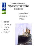
NondestructiveTesting
TableofContents
Chapter
No:
NameoftheChapter Page
No
1 Coursedailyschedule 1
2 CourseContents 2
3 IntroductionNDTprocesses&theirUses 311
4 IdentificationofweldDiscontinuities 1220
5 PenetrantTesting 2130
6 MagneticParticleTesting 31–48
7 UltrasonicTesting 4960
8 RadiographicTesting 6177
9 EddyCurrentTesting 7880
10 ComparisonandSelectionofNDT Methods 81
2
ChapterI
INTRODUCTION
NondestructiveTesting
The field ofNondestructive Testing(NDT)isaverybroad, that playsacritical rolein
assuringthatstructuralcomponentsandsystemsperformtheirfunctioninareliableand
costeffectivefashion.NDTtechniciansandengineersdefineandimplementteststhat
locate and characterize material conditions and flaws that might otherwise cause
seriousaccidentssuchas,planestocrash,reactorstofail,trainstoderail,pipelinesto
burst,andavarietyoftroublingevents.
Thesetestsareperformedinamannerthatdoesnotaffectthefutureusefulnessofthe
objectormaterial.Inotherwords,NDTallowspartsandmaterialstobeinspectedand
evaluatedwithoutdamagingthem.Becauseitallowsinspectionwithoutinterferingwith
a product's final use, NDT provides anexcellentbalancebetweenquality control and
costeffectiveness.
NondestructiveEvaluat ion
NondestructiveEvaluation(NDE)isatermthatisoftenusedinterchangeablywithNDT.
However,technically,NDEisusedtodescribemeasurementsthataremorequantitative
innature.Forexample,aNDEmethodwouldnotonlylocateadefect,butitwouldalso
be used to measure something about that defect such as its size, shape, and
orientation. NDE may be used to determine material properties such as fracture
toughness,ductility,conductivityandotherphysicalcharacteristics.
Useso fNDE
· FlawDetectionandEvaluation
· LeakDetection,LocationDetermination
· DimensionalMeasurements
· StructureandMicrostructureCharacterization
· EstimationofMechanicalandPhysicalProperties
· Stress(Strain)andDynamicResponseMeasurements
· MaterialSortingandChemicalCompositionDetermination
3
BackgroundonNondestructiveTesting(NDT)
Nondestructive testing has been practiced for many decades. One of the earliest
applicationswasthedetectionofsurfacecracksinrailcarwheelsandaxles.Theparts
weredippedinoil,thencleanedanddustedwithapowder.Whenacrackwaspresent,
theoilwouldseepfromthedefectandwettheoilprovidingvisualindicationindicating
that the component was flawed. This eventually led to oils that were specifically
formulatedforperformingtheseandotherinspectionsandtheseinspectiontechniques
arenowcalledpenetranttesting.
Xrayswerediscoveredin1895byWilhelmConradRoentgen(18451923)whowasa
Professor at Wuerzburg University in Germany. Soon after his discovery, Roentgen
produced the first industrial radiograph when he imaged a set of weights in a box to
show his colleagues. Other electronic inspection techniques such as ultrasonic and
eddy current testing started with the initial rapid developments in instrumentation
spurredbytechnologicaladvancesandsubsequentdefenseandspaceeffortsfollowing
World War II. In the early days, the primary purpose was the detection of defects.
Critical parts were produced with a "safe life" design, and were intendedto be defect
free during their useful life. The detection of defects was automatically a cause for
removalofthecomponentfromservice.
The continuedimprovementofinspection technology,inparticulartheability todetect
smaller andsmallerflaws,ledto moreandmore parts being rejected. Atthistimethe
disciplineoffracturemechanicsemerged,whichenabledonetopredictwhetheracrack
of a given size would fail under a particular load if a particular material property or
fracture toughness, were known. Other laws were developed to predict the rate of
growthofcracksundercyclicloading(fatigue).Withtheadventofthesetools,itbecame
possible to accept structures containing defects if the sizes of those defects were
known. This formed the basis for a new design philosophy called "damage tolerant
designs." Components having known defects could continue to be used aslong as it
couldbeestablishedthatthosedefectswouldnotgrowtoacriticalsizethatwouldresult
in catastrophic failure. A new challenge was thus presented to the nondestructive
testingcommunity.
Mere detection of flaws was not enough. One needed to also obtain quantitative
information about flaw size to serve as an input to fracturemechanics calculations to
predicttheremaininglifeofacomponent.Theseneeds,ledtothecreationofanumber
ofresearchprogramsaroundtheworldandtheemergenceofnondestructiveevaluation
(NDE)asanewdiscipline.
4
NDT/NDEMethods
The list of NDT methods that can be used to inspect components and make
measurementsislargeandcontinuestogrow.Researcherscontinuetofindnewways
of applying physics and other scientific disciplines to develop better NDT methods.
However, there are six NDT methods that are used most often. These methods are
Visual Inspection, Penetrant Testing, Magnetic Particle Testing, Electromagnetic or
EddyCurrentTesting,Radiography,andUltrasonicTesting.
VisualandOpticalT esting(VT)
Visual inspectioninvolvesusinganinspector's eyestolookfordefects.Theinspector
mayalsousespecialtoolssuchasmagnifyingglasses,mirrors,orborescopestogain
accessandmorecloselyinspectthesubjectarea.Visualexaminersfollowprocedures
thatrangefmsimpletoverycomplex.
PenetrantTesting(PT)
Test objects are coated with visible or fluorescent dye solution. Excess dye is then
removed fromthesurface, and a developeris applied.The developer actsasblotter,
drawing trappedpenetrantoutofimperfectionsopentothesurface.Withvisibledyes,
vividcolorcontrastsbetweenthepenetrantanddevelopermake"bleedout"easytosee.
With fluorescentdyes,ultravioletlightisusedto make thebleedoutfluorescebrightly,
thusallowingimperfectionstobereadilyseen.
5
MagneticParticleTest ing(MT)
This methodis accomplished byinducingamagnetic fieldinaferromagnetic material
and then dusting the surface with iron particles (either dry or suspended in liquid).
Surfaceandnearsurfaceimperfectionsdistortthemagneticfieldand concentrateiron
particlesnearimperfections,previewingavisualindicationoftheflaw.
ElectromagneticTesting(ET)orEddyCurrentTesting
Electrical currents are generated in a conductive material by an induced alternating
magnetic field This electrical currents is called eddy currents because they flow in
circles at and just below the surface of the material. Interruptions in the flow of eddy
currents, caused byimperfections, dimensional changes, or changes in the material's
conductiveandpermeabilityproperties,aredetected.
6
Radiography(RT)
Radiography involves the use of penetrating gamma or Xradiation to examine parts
andproductsforimperfections.AnXraygeneratororradioactiveisotopeisusedasa
sourceofradiation.Radiationisdirectedthroughapartandontofilmorotherimaging
media. The resulting radiograph shows the dimensional features of the part. Possible
imperfections are indicated as density changes on the film in the same manner as a
medicalXrayshowsbrokenbones.
UltrasonicT esting(UT)
Ultrasonics use transmission of highfrequency sound waves into a material to detect
imperfections or to locate changes in material properties. The most commonly used
ultrasonictestingtechniqueispulseecho,whereinsoundisintroducedintoatestobject
andreflections (echoes)are returned toareceiverfrominternalimperfectionsorfrom
thepart'sgeometricalsurfaces
.
crack
0 2 4 6 8 1
0
Initial
pulse
Crack
echo
Backsurface
echo
Sound
waves
Xrayfilm
Source
Rays
Objectwithdefect
Film
DefectImage
Filmwithimage
Probe
Couplant
Plate
Screen
7
AcousticEmissionTesting(AE)
Whenasolidmaterialisstressed,imperfectionswithinthematerialemitshortburstsof
acousticenergycalled"emissions."Asinultrasonictesting,acousticemissionscanbe
detectedbyspecialreceivers.Emissionsourcescanbeevaluatedthroughthestudyof
theirintensity,rate,andlocation.
LeakTesting(LT)
Severaltechniquesareusedtodetectandlocateleaksinpressurecontainmentparts,
pressure vessels, and structures. Leaks can be detected by using electronic listening
devices,pressuregaugemeasurements,liquidandgaspenetranttechniques,and/ora
simplesoapbubbletest.
8
Test
Method
UT Xray Eddy
Current
MPI LPT
Capitalcost
Mediumto
high
High Lowto
medium
Medium Low
Consumable
cost
Verylow High Low Medium Medium
Timeof
results
Immediate Delayed Immediate Short
delay
Short
delay
Effectof
geometry
Important Important Important Nottoo
Important
Nottoo
Important
Acc ess
problems
Important Important Important Important Important
Typeof
defect
Internal Most External External
Near
Surface
Surface
breaking
Relative
sensitivity
High Medium High Low Low
Operator
skill
High High Medium Low Low
Operator
training
Important Important Important Important Not
Important
Training
needs
High High Medium Low Low
Portabilityof
equipment
High Low Highto
medium
Highto
medium
High
Capabilities
Thickness
gauging,
composition
testing
Thickness
gauging
Thickness
gauging,
grade
sorting
Defects
only
Defects
only
The Relative Uses and Merits of Various NDT Methods
9
Table1ReferenceGuidetoMajorMethodsfortheNondestructive
ExaminationofWelds
Inspectio n
Method
Equipment
Required
Enables
Detectiortof
Advantages Limitations Remarks
Visual
Magnifying
glass
Weldsizing
gauge
Pocketrule
Straightedge
Workmanship
standards
Surfaceflaws
cracks,
porosity,
unfilled
craters,slag
inclusions
Warpage,
underwelding,
overwelding,
poorlyformed
beads,
misalignments,
improperfitup
Lowcost.
Canbeapplied
whileworkis
inprocess,
permitting
correctionof
faults.
Gives
indicationof
incorrect
procedures.
Applicable
tosurface
defectsonly.
Providesno
permanent
record.
Should
alwaysbethe
primary
methodof
inspection,no
matterwhat
other
techniquesare
required.
Istheonly
"productive"
typeof
inspection.
Isthe
necessary
functionof
everyonewho
inanyway
contributesto
themakingof
theweld.
Radiographic
Commercial
Xrayor
gammaunits
made
especiallyfor
inspecting
welds,
castingsand
forgings.
Filmand
processing
facilities.
Fluoroscopic
viewing
equipment.
Interior
macroscopic
flawscracks,
porosity,blow
holes,
nonmetallic
inclusions,
incomplete
root
penetration,
undercutting,
icicles,and
burnthrough.
Whenthe
indicationsare
recordedon
film,givesa
permanent
record.
Whenviewed
ona
fluoroscopic
screen,alow
costmethodof
internal
inspection
Requires
skillin
choosing
anglesof
exposure,
operating
equipment,
and
interpreting
indications.
Requires
safety
precautions.
Not
generally
suitablefor
filletweld
inspection.
Xray
inspectionis
requiredby
manycodes
and
specifications.
Usefulin
qualification
ofwelders
andwelding
processes.
Becauseof
cost,itsuse
shouldbe
limitedto
thoseareas
whereother
methodswill
notprovide
theassurance
required.
10
Magnetic
Particle
Special
commercial
equipment.
Magnetic
powders dry
orwetform;
maybe
fluorescent
forviewing
under
ultraviolet
light.
Excellentfor
detecting
surface
discontinuities
especially
surfacecracks.
Simplerto
usethan
radiographic
inspection.
Permits
controlled
sensitivity.
Relatively
lowcost
method.
Applicableto
ferromagnetic
materialsonly.
Requiresskill
in
interpretation
ofindications
and
recognitionof
irrelevant
patterns.
Difficulttouse
onrough
surfaces.
Elongated
defectsparallel
tothemagnetic
fieldmaynot
givepattern;
forthisreason
thefieldshould
beapplied
fromtwo
directionsator
nearright
anglestoeach
other.
Liquid
Penetrant
Commercial
kits
containing
fluorescentor
dyepenetrants
and
developers.
Application
equipmentfor
thedeveloper.
Asourceof
ultraviolet
light if
fluorescent
methodis
used.
Surfacecracks
notreadily
visibletothe
unaidedeye.
Excellentfor
locatingleaks
inweldments.
Applicableto
magneticand
nonmagnetic
materials.
Easytouse.
Lowcost.
Onlysurface
defectsare
detectable.
Cannotbe
used
effectivelyon
hotassemblies.
Inthinwalled
vesselswill
revealleaksnot
ordinarily
locatedby
usualairtests.
irrelevant
surface
conditions
(smoke,slag)
maygive
misleading
indications.
Ultrasonic
Special
commercial
equipment,
eitherofthe
pulseechoor
transmission
type.
Standard
reference
patternsfor
interpretation
ofRFor
video
patterns.
Surfaceand
subsurface
flawsincluding
thosetoosmall
tobedetected
byother
methods.
Especiallyfor
detecting
subsurface
laminationlike
defects.
Very
sensitive.
Permits
probingof
joints
inaccessible
to
radiography.
Requireshigh
degreeofskill
ininterpreting
pulseecho
patterns.
Permanent
recordisnot
readily
obtained.
Pulseecho
equipmentis
highly
developedfor
weldinspection
purposes.
The
transmission
typeequipment
simplifies
pattern
interpretation
whereitis
applicable.
11
ChapterII
IDENTIFICATIONOFWELDDISCONTINUITIES
Discontinuities are interruptions in the typical structure of a material. These interruptions
may occur in the base metal, weld material or "heat affected" zones. Discontinuities,
which do not meet the requirements of the codes or specification used to invoke and
control an inspection, are referred to as defects.
General Welding Discontinuities
The following discontinuities are typical of all types of welding.
Cracks:
Crack is tight linear separations of metal that can be very short to very long indications.
Cracks are grouped as hot or cold cracks. Hot cracks usually occur as the metal
solidifies at elevated temperatures. Cold cracks occur after the metal has cooled to
ambient temperatures ( delayed cracks).
Cracks can be detected in a radiograph only when they are propagating in a direction
that produces a change in thickness that is parallel to the x-ray beam. Cracks will
appear as jagged and often very faint irregular lines. Cracks can sometimes appear as
"tails" on inclusions or porosity.
12
Lack of Fusion:
Lack of fusion (Cold Lap) is a condition where the weld filler metal does not properly
fuse with the base metal or the previous weld pass material (inter pass cold lap). The
arc does not melt the base metal sufficiently and causes the slightly molten puddle to
flow into base material without bonding.
13
Porosity:
Porosity is the result of gas entrapment in the solidifying metal. Porosity can take many
shapes on a radiograph but often appears as dark round or irregular spots or specks
appearing singularly, in clusters or rows. Sometimes porosity is elongated and may
have the appearance of having a tail This is the result of gas attempting to escape while
the metal is still in a liquid state and is called wormhole porosity. All porosity is a void in
the material it will have a radiographic density more than the surrounding area.
Cluster porosity:
Cluster porosity is caused when flux coated electrodes are contaminated with moisture.
The moisture turns into gases when heated and becomes trapped in the weld during the
welding process. Cluster porosity appear just like regular porosity in the radiograph but
the indications will be grouped close
together.
14
Slag inclusions:
Slag inclusions are nonmetallic solid material entrapped in weld metal or between weld
and base metal. In a radiograph, dark, jagged asymmetrical shapes within the weld or
along the weld joint areas are indicative of slag inclusions.
Incomplete penetration (IP):
Incomplete penetration (IP) or lack of penetration (LOP) occurs when the weld metal
fails to penetrate the joint. It is one of the most objectionable weld discontinuities. Lack
of penetration allows a natural stress riser from which a crack may propagate. The
appearance on a radiograph is a dark area with well-defined, straight edges that follows
the land or root face down the center of the weldment.
Root concavity:
15
Root or Internal concavity or suck back is condition where the weld metal has
contracted as it cools and has been drawn up into the root of the weld. On a radiograph
it looks similar to lack of penetration but the line has irregular edges and it is often quite
wide in the center of the weld image.
Internal or root undercut:
Internal or root undercut is an erosion of the base metal next to the root of the weld. In
the radiographic image it appears as a dark irregular line offset from the centerline of
the weldment. Undercutting is not as straight edged as LOP because it does not follow
a ground edge.
External or crown undercut:
16
External or crown undercut is an erosion of the base metal next to the crown of the
weld. In the radiograph, it appears as a dark irregular line along the outside edge of the
weld area.
Offset or mismatch:
Offset or mismatch are terms associated with a condition where two pieces being
welded together are not properly aligned. The radiographic image is a noticeable
difference in density between the two pieces. The difference in density is caused by the
difference in material thickness. The dark, straight line is caused by failure of the weld
metal to fuse with the land area.
Inadequate weld reinforcement:
17
Inadequate weld reinforcement is an area of a weld where the thickness of weld metal
deposited is less than the thickness of the base material. It is very easy to determine by
radiograph if the weld has inadequate reinforcement, because the image density in the
area of suspected inadequacy will be more (darker) than the image density of the
surrounding base material.
Excess weld reinforcement :
Excess weld reinforcement is an area of a weld that has weld metal added in excess of
that specified by engineering drawings and codes. The appearance on a radiograph is a
localized, lighter area in the weld. A visual inspection will easily determine if the weld
reinforcement is in excess of that specified by the engineering requirements.
Discontinuities in TIG welds
18
The following discontinuities are peculiar to the TIG welding process. These
discontinuities occur in most metals welded by the process including aluminum and
stainless steels. The TIG method of welding produces a clean homogeneous weld
which when radiographed is easily interpreted.
Tungsten inclusions.
Tungsten is a brittle and inherently dense material used in the electrode in tungsten
inert gas ( TIG ) welding. If improper welding procedures are used, tungsten may be
entrapped in the weld. Radiographically, tungsten is denser than aluminum or steel;
therefore, it shows as a lighter area with a distinct outline on the radiograph.
Oxide inclusions:
Oxide inclusions are usually visible on the surface of material being welded (especially
aluminum). Oxide inclusions are less dense than the surrounding materials and,
therefore, appear as dark irregularly shaped discontinuities in the
radiograph.
Discontinuities in Gas Metal Arc Welds (GMAW)
The following discontinuities are most commonly found in GMAW welds.
19
Whiskers:
Whiskers are short lengths of weld electrode wire, visible on the top or bottom surface
of the weld or contained within the weld. On a radiograph they appear as light, "wire
like" indications.
Burn-Through:
Burn-Through results when too much heat causes excessive weld metal to penetrate
the weld zone. Often lumps of metal sag through the weld creating a thick globular
condition on the back of the weld. These globs of metal are referred to as icicles. On a
radiograph, burn through appears as dark spots, which are often surrounded by light
globular areas (icicles).
20
ChapterIII
PENE TRANTINSPECTION
Introduction
Liquidpenetrationinspectionisamethodthatisusedtorevealsurfacebreakingflaws
bybleedoutofacoloredorfluorescentdyefromtheflaw.Thetechniqueisbasedonthe
abilityofaliquidtobedrawnintoa"clean"surfacebreakingflawbycapillaryaction.
After a period of time called the "dwell," excess surface penetrant is removed and a
developer is applied. This acts as a "blotter." It draws the penetrant from the flaw to
revealitspresence.
Colored(contrast)penetrantsrequiregoodwhitelightwhilefluorescentpenetrantsneed
tobeviwedindarkenedconditionswithanultraviolet"blacklight".
A very early surface inspection technique involved the rubbing of carbon black on
glazedpottery,wherebythecarbonblackwouldsettleinsurfacecracksrenderingthem
visible. Later it became the practice in railway workshops to examine iron and steel
components by the "oil and whiting" method. In this method, heavy oil commonly
available in railway workshops was diluted with kerosene in large tanks so that
locomotive parts such as wheels could be submerged. After removal and careful
cleaning,thesurfacewasthencoatedwithafinesuspensionofchalkinalcoholsothat
awhitesurfacelayerwasformedoncethealcoholhadevaporated.Theobjectwasthen
vibrated and stroked withahammer, causingtheresidualoilinany surfacecracksto
seepoutandstainthewhitecoating.
Thismethodwasinusefromthelatterpartofthe19thcenturythroughtoapproximately
1940, when the magnetic particle method was introduced and found to be more
sensitive for the ferromagnetic iron and steels. Penetrant Inspection Improves the
DetectabilityofFlaws
The advantage that a liquid penetrant inspection (LPI) offers over an unaided visual
inspectionisthatit makesdefectseasiertosee for theinspector. Thereare basically
twowaysthatapenetrantinspectionprocessmakesflawsmoreeasilyseen.First,LPI
producesaflawindicationthatismuchlargerandeasierfortheeyetodetectthanthe
flawitself.Manyflawsaresosmallornarrowthattheyareundetectablebytheunaided
eye.
ThesecondwaythatLPIimprovesthedetectabilityofaflawisthatitproducesaflaw
indicationwithahighlevelofcontrastbetweentheindicationandthebackgroundwhich
alsohelpstomaketheindicationmoreeasilyseen.Whena
visible dye penetrant inspection is performed, the penetrant materials are formulated
usingabrightreddyethatprovidesforahighlevelofcontrast
21
betweenthewhitedeveloperthatservesasabackgroundaswellastopullthetrapped
penetrant from the flaw. When a fluorescent penetrant inspection is performed, the
penetrantmaterialsareformulatedtoglowbrightlyandtogiveofflightatawavelength
thattheeyeismostsensitivetounderdimlightingconditions.
BasicProcessingStepsofaLiquidPenetrantInspectio n
1. Surfac e Preparation: One of the most critical steps of a liquid penetrant
inspection is the surface preparation. The surface must be free of oil, grease,
water,orothercontaminantsthatmaypreventpenetrantfromenteringflaws.The
sample may also require etching if mechanical operations such as machining,
sanding, or grit blasting have been performed. These and other mechanical
operationscansmearthesurfaceofthesample,thusclosingthedefects.
2. PenetrantApplication:Oncethesurfacehasbeenthoroughlycleanedanddried,
the penetrant material is applied on the surface by spraying, brushing, or
immersingthepartsinapenetrantbath.
3. Penetrant Dwell:Thepenetrantisleftonthesurfaceforasufficienttimetoallow
as much penetrant as possible to be drawn from or to seep into a defect.
Penetrantdwelltimeisthetotaltimethatthepenetrantisincontactwiththepart
surface.Dwelltimesareusuallyrecommendedbythe
penetrant producers or required by the specification being followed. The times
varydependingontheapplication,penetrantmaterialsused,thematerialbeing
inspected,andthetypeofdefectbeinginspected.Minimumdwelltimestypically
range from 5 to 60 minutes. Generally, there is no harm in using a longer
22
penetrant dwell time as long as the penetrant is not allowed to dry. The ideal
dwelltimeisoftendeterminedbyexperimentationandisoftenveryspecifictoa
particularapplication.
4 Excess Penetrant Removal: This is a most delicate part of the inspection
procedure becausethe excess penetrant mustberemoved from the surface of
the sample while removing as little penetrant as possible from defects.
Dependingonthepenetrantsystemused,thisstepmayinvolvecleaningwitha
solvent, direct rinsing with water, or first treated with an emulsifier and then
rinsingwithwater.
5 DeveloperApplication:Athinlayerofdeveloperisthenappliedtothesample
to draw penetrant trapped in flaws back to the surface where it will be visible.
Developers come in a variety of forms that may be applied by dusting (dry
powdered),dipping,orspraying(wetdevelopers).
6 IndicationDevelopment:Thedeveloperisallowedtostandonthepartsurface
foraperiodoftimesufficienttopermittheextractionofthetrappedpenetrantout
ofanysurfaceflaws.Thisdevelopmenttimeisusuallyaminimumof10minutes
andsignificantlylongertimesmaybenecessaryfortightcracks.
7 Inspection: Inspection is then performed under appropriate lighting to detect
indicationsfromanyflawsthatmaybepresent.
8 Clean Surface: The final step in the process is to thoroughly clean the part
surfacetoremovethedeveloperfromthepartsthatwerefoundtobeacceptable.
PenetrantTestingMaterials
The penetrant materials used today are much more sophisticated than the kerosene
andwhitingfirstusedbyrailroadinspectorsneartheturnofthe20thcentury.Today's
penetrants are carefully formulated to produce the level of sensitivity desired by the
inspector.
1 Penetrant: Penetrant materials are classified in the various industry and
governmentspecificationsbytheirphysicalcharacteristicsandtheirperformance
Penetrant materials come in two basic types. These types are listed below:
· Type 1 - Fluorescent Penetrants
· Type2VisiblePenetrants
Fluorescentpenetrants containa dyeor several dyesthatfluoresce whenexposed to
ultraviolet radiation. Visible penetrants contain a red dye that provides high contrast
against the white developer background. Fluorescent penetrant systems are more
sensitive than visible penetrant systems because the eyeis drawn to the glow of the
fluorescingindication.However,visiblepenetrantsdonotrequireadarkenedareaand
an ultraviolet light in order to make an inspection. Visible penetrants are also less
vulnerable to contamination from things such as cleaning fluid that can significantly
reducethestrengthofafluorescentindication.
23
Penetrantsarethenclassifiedbythemethodusedtoremovetheexcesspenetrantfrom
thepart.Thefourmethodsarelistedbelow:
· MethodAWaterWashable
· MethodBPostEmulsifiable,Lipophilic
· MethodCSolventRemovable
· MethodDPostEmulsifiable,Hydrophilic
Waterwashable(MethodA)penetrantscanberemovedfromthepartbyrinsingwith
wateralone.Thesepenetrantscontainsomeemulsifyingagent(detergent)thatmakesit
possibletowashthepenetrantfromthepartsurfacewithwateralone.Waterwashable
penetrantsaresometimesreferredtoasselfemulsifyingsystems.
Post emulsifiable penetrants come in two varieties, lipophilic and hydrophilic. In post
emulsifiers,lipophilicsystems(MethodB),thepenetrantisoilsolubleandinteractswith
the oilbased emulsifier to make removal possible. Post emulsifiable, hydrophilic
systems(MethodD),useanemulsifierthatisawatersolubledetergentwhichliftsthe
excess penetrant from the surface of the part with a water wash. Solvent removable
penetrantsrequiretheuseofasolventtoremovethepenetrantfromthepart.
PropertiesofgoodPenetrant
Toperformwell,apenetrantmustpossessfollowingimportantcharacteristics.
· spread easily over the surface of the material being inspected to provide
completeandevencoverage.
· bedrawnintosurfacebreakingdefectsbycapillaryaction.
· remaininthedefectbutremoveeasilyfromthesurfaceofthepart.
· remainfluidsoitcanbedrawnbacktothesurfaceofthepartthroughthedrying
anddevelopingsteps.
· behighlyvisibleorfluorescebrightlytoproduceeasytoseeindications.
· mustnotbeharmfultothematerialbeingtestedortheinspector.
2Emulsifiers: Whenremovalofthepenetrantfromthedefectduetooverwashing
of the part is a concern, a post emulsifiable penetrant system can be used. Post
emulsifiablepenetrantsrequireaseparateemulsifiertobreakthepenetrant downand
make it water washable. Most penetrant inspection specifications classify penetrant
systemsintofourmethodsofexcesspenetrantremoval.Thesearelistedbelow:
1. MethodA:WaterWashable
2. MethodB:PostEmulsifiable,Lipophilic
24
3. MethodC:SolventRemovable
4. MethodD:PostEmulsifiable,Hydrophilic
Method C relies on a solvent cleaner to remove the penetrant from the part being
inspected.MethodAhasemulsifiersbuiltintothepenetrantliquidthatmakesitpossible
toremovetheexcesspenetrantwithasimplewaterwash.MethodBandDpenetrants
requireanadditionalprocessingstepwhereaseparateemulsificationagentisapplied
to make the excess penetrant more removable with a water wash. Lipophilic
emulsification systems are oilbased materials that are supplied in readytouse form.
Hydrophilic systems are waterbased and supplied as a concentrate that must be
dilutedwithwaterpriortouse .Lipophilicemulsifiers(MethodB)wereintroducedinthe
late1950'sandwork withbothachemical andmechanicalaction.Aftertheemulsifier
has coated the surfaceofthe object, mechanicalaction starts to remove some of the
excesspenetrantasthemixturedrainsfromthepart.Duringtheemulsificationtime,the
emulsifier diffuses into the remaining penetrant and the resulting mixture is easily
removedwithawaterspray.
Hydrophilicemulsifiers(MethodD)also removetheexcesspenetrantwith mechanical
and chemical action but the action is different because no diffusion takes place.
Hydrophilic emulsifiers are basically detergents that contain solvents and surfactants.
The hydrophilic emulsifier breaks up the penetrant into small quantities and prevents
thesepiecesfromrecombiningorreattachingtothesurfaceofthepart.Themechanical
action of the rinse water removes the displaced penetrant from the part and causes
freshremovertocontactandliftnewlyexposedpenetrantfromthesurface.
Thehydrophilicpostemulsifiablemethod(MethodD)wasintroducedinthemid1970's
andsinceitismoresensitivethanthelipophilicpostemulsifiable method ithasmade
the later method virtually obsolete. The major advantage of hydrophilic emulsifiers is
that they are less sensitive to variation in the contact and removal time. While
emulsificationtimeshouldbecontrolledascloselyaspossible,avariationofoneminute
ormoreinthecontacttimewillhavelittleeffectonflawdetectabilitywhenahydrophilic
emulsifier is used. However, a variation of as little as 15 to 30 seconds can have a
significanteffectwhenalipophilicsystemisused.
3Developers
Theroleofthedeveloperistopullthetrappedpenetrantmaterialoutofdefectsandto
spreadthedeveloperoutonthesurfaceofthepartsoitcanbeseenbyaninspector.
Thefinedeveloperparticlesbothreflectandrefracttheincidentultravioletlight,allowing
more of it to interact with the penetrant, causing more efficient fluorescence. The
developer also allows more light to be emitted through the same mechanism. This is
why indications are brighter than the penetrant itself under UV light. Another function
that some developers performs is to create a white background so there is a greater
degreeofcontrastbetweentheindicationandthesurroundingbackground.
DeveloperForms
25
The AMS 2644 and MilI25135 classify developers into six standard forms. These
formsarelistedbelow:
1. FormaDryPowder
2. FormbWaterSoluble
3. FormcWaterSuspendible
4. FormdNonaqueousType1Fluorescent(SolventBased)
5. FormeNonaqueousType2VisibleDye(SolventBased)
The developer classifications are based on the method that the developer is applied.
The developer can beappliedas a drypowder,ordissolvedor suspendedin aliquid
carrier.Eachofthedeveloperformshasadvantagesanddisadvantages.
A)DryPowder
Dry powder developer is generally considered to be the least sensitive but it is
inexpensivetouseandeasytoapply.Drydevelopersarewhite,fluffypowdersthatcan
be applied to a thoroughly dry surface in a number of ways. The developer can be
applied bydippingpartsinacontainerofdeveloper,orbyusinga puffertodustparts
withthedeveloper.Partscanalsobeplacedina dustcabinetwherethedeveloperis
blown around and allowed to settle on the part. Electrostatic powder spray guns are
also available to apply the developer. The goal is to allow the developer to come in
contactwiththewholeinspectionarea.
Unlessthepartiselectrostaticallycharged,thepowderwillonlyadheretoareaswhere
trapped penetrant has wet the surface of the part. The penetrant will try to wet the
surface of the penetrant particle and fill thevoids between the particles, which brings
more penetrant to the surface of the part where it can be seen. Since dry powder
developersonlysticktothepartwherepenetrantispresent,thedrydeveloperdoesnot
provide a uniform white background as the other forms of developers do. Having a
uniform light background is very important for a visible inspection to be effective and
sincedrydevelopersdonotprovideone,theyareseldomusedforvisibleinspections.
When a dry developer is used, indications tend to stay bright and sharp since the
penetranthasalimitedamountofroomtospread.
B) - Water Soluble
Asthenameimplies,watersolubledevelopersconsistofagroupofchemicalsthatare
dissolvedinwaterandformadeveloperlayerwhenthewaterisevaporatedaway.The
bestmethodforapplyingwatersolubledevelopersisbysprayingitonthepart.Thepart
can be wet or dry. Dipping, pouring, or brushing the solution on to the surface is
sometimes used but these methods are less desirable. Aqueous developers contain
wettingagentsthatcausethesolutiontofunctionmuchlikedilutehydrophilicemulsifier
and can lead to additional removal of entrapped penetrant. Drying is achieved by
placingthewetbutwelldrained
partinarecalculatingwarmairdryerwiththetemperatureheldbetween70and75°F.If
thepartsarenotdriedquickly,theindicationswillwillbeblurredandindistinct.Properly
developedpartswillhaveaneven,palewhitecoatingovertheentiresurface.