Tài liệu về micrologix 1000
Bạn đang xem bản rút gọn của tài liệu. Xem và tải ngay bản đầy đủ của tài liệu tại đây (1.73 MB, 422 trang )
User
Manual
MicroLogixt 1000
Programmable
Controllers
(Bulletin
1761 Controllers)
Allen-Bradley
Important User Information
Because of the variety of uses for the products described in this publication, those
responsible for the application and use of this control equipment must satisfy
themselves that all necessary steps have been taken to assure that each application
and use meets all performance and safety requirements, including any applicable
laws, regulations, codes, and standards.
The illustrations, charts, sample programs and layout examples shown in this guide
are intended solely for purposes of example. Since there are many variables and
requirements associated with any particular installation, Allen-Bradley does not
assume responsibility or liability (to include intellectual property liability) for actual
use based on the examples shown in this publication.
Allen-Bradley publication SGI-1.1, Safety Guidelines for the Application,
Installation, and Maintenance of Solid-State Control (available from your local
Allen-Bradley office), describes some important dif
ferences between solid-state
equipment and electromechanical devices that should be taken into consideration
when applying products such as those described in this publication.
Reproduction of the contents of this copyrighted publication, in whole or in part,
without written permission of Allen-Bradley Company, Inc., is prohibited.
Throughout this manual, we use notes to make you aware of safety considerations:
Identifies information about practices or circumstances that can lead to
personal injury or death, property damage, or economic loss.
Attention statements help you to:
• identify a hazard
• avoid the hazard
•
recognize the consequences
Note Identifies information that is critical for successful application and
understanding of the product.
SLC 500, SLC 5/01, SLC 5/02, SLC 5/03, SLC 5/04, MicroLogix, DTAM, DTAM Micro, PanelView, RediPANEL, Dataliner, DH+, and
Data Highway Plus are trademarks of Rockwell Automation.
PLC-2, PLC-5 are registered trademarks of Rockwell Automation.
A.I. Series and WINtelligent LINX are trademarks of Rockwell Software Inc.
T
able of Contents
toc–i
Table of Contents
Preface P–1.
. . . . . . . . . . . . . . . . . . . . . . . . . . . . . . . . . . . . . . . . . . . . . . . . . . . . . . . . . . . . . . . . . . . . . . .
Who
Should Use this Manual
P–2. . . . . . . . . . . . . . . . . . . . . . . . . . . . . . . . . . . . . . . . . . . . . . .
Purpose of this Manual
P–2. . . . . . . . . . . . . . . . . . . . . . . . . . . . . . . . . . . . . . . . . . . . . . . . . . . .
Common T
echniques Used in this Manual
P–6. . . . . . . . . . . . . . . . . . . . . . . . . . . . . . . . . . . . .
Allen-Bradley Support P–6. . . . . . . . . . . . . . . . . . . . . . . . . . . . . . . . . . . . . . . . . . . . . . . . . . . .
Hardware
1 Installing
Y
our Controller 1–1.
. . . . . . . . . . . . . . . . . . . . . . . . . . . . . . . . . . . . . . . . . . . . . .
Compliance to European Union Directives 1–2. . . . . . . . . . . . . . . . . . . . . . . . . . . . . . . . . . . .
Hardware Overview 1–3. . . . . . . . . . . . . . . . . . . . . . . . . . . . . . . . . . . . . . . . . . . . . . . . . . . . . .
Master Control Relay
1–4. . . . . . . . . . . . . . . . . . . . . . . . . . . . . . . . . . . . . . . . . . . . . . . . . . . . .
Using Sur
ge Suppressors
1–8. . . . . . . . . . . . . . . . . . . . . . . . . . . . . . . . . . . . . . . . . . . . . . . . . . .
Safety Considerations
1–11. . . . . . . . . . . . . . . . . . . . . . . . . . . . . . . . . . . . . . . . . . . . . . . . . . . .
Power Considerations
1–12. . . . . . . . . . . . . . . . . . . . . . . . . . . . . . . . . . . . . . . . . . . . . . . . . . . .
Preventing Excessive Heat
1–13. . . . . . . . . . . . . . . . . . . . . . . . . . . . . . . . . . . . . . . . . . . . . . . .
Controller Spacing 1–14. . . . . . . . . . . . . . . . . . . . . . . . . . . . . . . . . . . . . . . . . . . . . . . . . . . . . .
Mounting the Controller 1–14. . . . . . . . . . . . . . . . . . . . . . . . . . . . . . . . . . . . . . . . . . . . . . . . . .
2 Wiring
Y
our Controller 2–1.
. . . . . . . . . . . . . . . . . . . . . . . . . . . . . . . . . . . . . . . . . . . . . . . . .
Grounding
Guidelines
2–2. . . . . . . . . . . . . . . . . . . . . . . . . . . . . . . . . . . . . . . . . . . . . . . . . . . . .
Sinking and Sourcing Circuits 2–3. . . . . . . . . . . . . . . . . . . . . . . . . . . . . . . . . . . . . . . . . . . . . .
W
iring Recommendations
2–4. . . . . . . . . . . . . . . . . . . . . . . . . . . . . . . . . . . . . . . . . . . . . . . . . .
Wiring Diagrams, Discrete Input and Output V
oltage Ranges
2–7. . . . . . . . . . . . . . . . . . . . . .
Analog Cable Recommendation
2–21. . . . . . . . . . . . . . . . . . . . . . . . . . . . . . . . . . . . . . . . . . . .
Minimizing Electrical Noise on Analog Controllers 2–21. . . . . . . . . . . . . . . . . . . . . . . . . . . .
Wiring Y
our Analog Channels
2–22. . . . . . . . . . . . . . . . . . . . . . . . . . . . . . . . . . . . . . . . . . . . .
Analog Voltage and Current Input and Output Ranges 2–23. . . . . . . . . . . . . . . . . . . . . . . . . . .
Wiring Your Controller for High–Speed Counter Applications 2–24. . . . . . . . . . . . . . . . . . . .
3 Connecting the System 3–1.
. . . . . . . . . . . . . . . . . . . . . . . . . . . . . . . . . . . . . . . . . . . . . . . .
Connecting the DF1 Protocol 3–2. . . . . . . . . . . . . . . . . . . . . . . . . . . . . . . . . . . . . . . . . . . . . . .
Connecting to a DH-485 Network 3–5. . . . . . . . . . . . . . . . . . . . . . . . . . . . . . . . . . . . . . . . . . .
Connecting the AIC+
3–9. . . . . . . . . . . . . . . . . . . . . . . . . . . . . . . . . . . . . . . . . . . . . . . . . . . . .
Preface
MicroLogix 1000 Programmable Controllers User Manual
toc–ii
Establishing Communication 3–17. . . . . . . . . . . . . . . . . . . . . . . . . . . . . . . . . . . . . . . . . . . . . .
DeviceNet Communications
3–18. . . . . . . . . . . . . . . . . . . . . . . . . . . . . . . . . . . . . . . . . . . . . . .
Programming
4 Programming Overview 4–1.
. . . . . . . . . . . . . . . . . . . . . . . . . . . . . . . . . . . . . . . . . . . . . . . .
Principles of Machine Control 4–2. . . . . . . . . . . . . . . . . . . . . . . . . . . . . . . . . . . . . . . . . . . . . .
Understanding File Organization 4–4. . . . . . . . . . . . . . . . . . . . . . . . . . . . . . . . . . . . . . . . . . . .
Understanding How Processor Files are Stored and Accessed
4–6. . . . . . . . . . . . . . . . . . . . . .
Addressing Data Files
4–10. . . . . . . . . . . . . . . . . . . . . . . . . . . . . . . . . . . . . . . . . . . . . . . . . . . .
Applying Ladder Logics to Your Schematics 4–14. . . . . . . . . . . . . . . . . . . . . . . . . . . . . . . . . .
Developing Your Logic Program – A Model 4–15. . . . . . . . . . . . . . . . . . . . . . . . . . . . . . . . . .
5 Using Analog 5–1.
. . . . . . . . . . . . . . . . . . . . . . . . . . . . . . . . . . . . . . . . . . . . . . . . . . . . . . . .
I/O Image 5–2. . . . . . . . . . . . . . . . . . . . . . . . . . . . . . . . . . . . . . . . . . . . . . . . . . . . . . . . . . . . . .
I/O Configuration 5–3. . . . . . . . . . . . . . . . . . . . . . . . . . . . . . . . . . . . . . . . . . . . . . . . . . . . . . . .
Input Filter and Update Times 5–3. . . . . . . . . . . . . . . . . . . . . . . . . . . . . . . . . . . . . . . . . . . . . .
Converting Analog Data 5–5. . . . . . . . . . . . . . . . . . . . . . . . . . . . . . . . . . . . . . . . . . . . . . . . . . .
6 Using Basic Instructions 6–1.
. . . . . . . . . . . . . . . . . . . . . . . . . . . . . . . . . . . . . . . . . . . . . . .
About
the Basic Instructions
6–2. . . . . . . . . . . . . . . . . . . . . . . . . . . . . . . . . . . . . . . . . . . . . . . .
Bit Instructions Overview 6–3. . . . . . . . . . . . . . . . . . . . . . . . . . . . . . . . . . . . . . . . . . . . . . . . . .
Examine if Closed (XIC) 6–4. . . . . . . . . . . . . . . . . . . . . . . . . . . . . . . . . . . . . . . . . . . . . . . . . .
Examine if Open (XIO) 6–4. . . . . . . . . . . . . . . . . . . . . . . . . . . . . . . . . . . . . . . . . . . . . . . . . . . .
Output Energize (OTE) 6–5. . . . . . . . . . . . . . . . . . . . . . . . . . . . . . . . . . . . . . . . . . . . . . . . . . . .
Output Latch (OTL) and Output Unlatch (OTU) 6–5. . . . . . . . . . . . . . . . . . . . . . . . . . . . . . . .
One-Shot Rising (OSR) 6–7. . . . . . . . . . . . . . . . . . . . . . . . . . . . . . . . . . . . . . . . . . . . . . . . . . .
Timer Instructions Overview 6–8. . . . . . . . . . . . . . . . . . . . . . . . . . . . . . . . . . . . . . . . . . . . . . .
Timer On-Delay (TON) 6–11. . . . . . . . . . . . . . . . . . . . . . . . . . . . . . . . . . . . . . . . . . . . . . . . . .
Timer Off-Delay (TOF) 6–12. . . . . . . . . . . . . . . . . . . . . . . . . . . . . . . . . . . . . . . . . . . . . . . . . .
Retentive Timer (RTO) 6–14. . . . . . . . . . . . . . . . . . . . . . . . . . . . . . . . . . . . . . . . . . . . . . . . . . .
Counter Instructions Overview 6–15. . . . . . . . . . . . . . . . . . . . . . . . . . . . . . . . . . . . . . . . . . . . .
Count Up (CTU) 6–18. . . . . . . . . . . . . . . . . . . . . . . . . . . . . . . . . . . . . . . . . . . . . . . . . . . . . . . .
Count Down (CTD) 6–19. . . . . . . . . . . . . . . . . . . . . . . . . . . . . . . . . . . . . . . . . . . . . . . . . . . . .
Reset (RES) 6–20. . . . . . . . . . . . . . . . . . . . . . . . . . . . . . . . . . . . . . . . . . . . . . . . . . . . . . . . . . . .
Basic Instructions in the Paper Drilling Machine Application Example 6–21. . . . . . . . . . . . .
7 Using Comparison Instructions 7–1.
. . . . . . . . . . . . . . . . . . . . . . . . . . . . . . . . . . . . . . . .
About the Comparison Instructions 7–2. . . . . . . . . . . . . . . . . . . . . . . . . . . . . . . . . . . . . . . . . .
Comparison Instructions Overview 7–2. . . . . . . . . . . . . . . . . . . . . . . . . . . . . . . . . . . . . . . . . . .
T
able of Contents
toc–iii
Equal (EQU) 7–3. . . . . . . . . . . . . . . . . . . . . . . . . . . . . . . . . . . . . . . . . . . . . . . . . . . . . . . . . . . .
Not Equal (NEQ) 7–3. . . . . . . . . . . . . . . . . . . . . . . . . . . . . . . . . . . . . . . . . . . . . . . . . . . . . . . .
Less Than (LES) 7–3. . . . . . . . . . . . . . . . . . . . . . . . . . . . . . . . . . . . . . . . . . . . . . . . . . . . . . . . .
Less Than or Equal (LEQ) 7–4. . . . . . . . . . . . . . . . . . . . . . . . . . . . . . . . . . . . . . . . . . . . . . . . .
Greater Than (GRT) 7–4. . . . . . . . . . . . . . . . . . . . . . . . . . . . . . . . . . . . . . . . . . . . . . . . . . . . . .
Greater Than or Equal (GEQ) 7–4. . . . . . . . . . . . . . . . . . . . . . . . . . . . . . . . . . . . . . . . . . . . . . .
Masked Comparison for Equal (MEQ) 7–5. . . . . . . . . . . . . . . . . . . . . . . . . . . . . . . . . . . . . . . .
Limit Test (LIM) 7–6. . . . . . . . . . . . . . . . . . . . . . . . . . . . . . . . . . . . . . . . . . . . . . . . . . . . . . . . .
Comparison Instructions in the Paper Drilling Machine Application Example 7–8. . . . . . . . .
8 Using Math Instructions 8–1.
. . . . . . . . . . . . . . . . . . . . . . . . . . . . . . . . . . . . . . . . . . . . . . .
About
the Math Instructions
8–2. . . . . . . . . . . . . . . . . . . . . . . . . . . . . . . . . . . . . . . . . . . . . . . .
Math Instructions Overview 8–2. . . . . . . . . . . . . . . . . . . . . . . . . . . . . . . . . . . . . . . . . . . . . . . .
Add (ADD) 8–4. . . . . . . . . . . . . . . . . . . . . . . . . . . . . . . . . . . . . . . . . . . . . . . . . . . . . . . . . . . . .
Subtract (SUB) 8–5. . . . . . . . . . . . . . . . . . . . . . . . . . . . . . . . . . . . . . . . . . . . . . . . . . . . . . . . . .
32-Bit Addition and Subtraction 8–6. . . . . . . . . . . . . . . . . . . . . . . . . . . . . . . . . . . . . . . . . . . . .
Multiply (MUL) 8–8. . . . . . . . . . . . . . . . . . . . . . . . . . . . . . . . . . . . . . . . . . . . . . . . . . . . . . . . .
Divide (DIV) 8–9. . . . . . . . . . . . . . . . . . . . . . . . . . . . . . . . . . . . . . . . . . . . . . . . . . . . . . . . . . . .
Double Divide (DDV) 8–10. . . . . . . . . . . . . . . . . . . . . . . . . . . . . . . . . . . . . . . . . . . . . . . . . . . .
Clear (CLR) 8–11. . . . . . . . . . . . . . . . . . . . . . . . . . . . . . . . . . . . . . . . . . . . . . . . . . . . . . . . . . . .
Square Root (SQR) 8–11. . . . . . . . . . . . . . . . . . . . . . . . . . . . . . . . . . . . . . . . . . . . . . . . . . . . . .
Scale Data (SCL) 8–12. . . . . . . . . . . . . . . . . . . . . . . . . . . . . . . . . . . . . . . . . . . . . . . . . . . . . . .
Math Instructions in the Paper Drilling Machine Application Example 8–14. . . . . . . . . . . . .
9 Using Data Handling Instructions 9–1.
. . . . . . . . . . . . . . . . . . . . . . . . . . . . . . . . . . . . . .
About the Data Handling Instructions 9–2. . . . . . . . . . . . . . . . . . . . . . . . . . . . . . . . . . . . . . . .
Convert to BCD (TOD) 9–3. . . . . . . . . . . . . . . . . . . . . . . . . . . . . . . . . . . . . . . . . . . . . . . . . . . .
Convert from BCD (FRD) 9–5. . . . . . . . . . . . . . . . . . . . . . . . . . . . . . . . . . . . . . . . . . . . . . . . .
Decode 4 to 1 of 16 (DCD) 9–8. . . . . . . . . . . . . . . . . . . . . . . . . . . . . . . . . . . . . . . . . . . . . . . . .
Encode 1 of 16 to 4 (ENC) 9–9. . . . . . . . . . . . . . . . . . . . . . . . . . . . . . . . . . . . . . . . . . . . . . . . .
Copy File (COP) and Fill File (FLL) Instructions 9–10. . . . . . . . . . . . . . . . . . . . . . . . . . . . . .
Move and Logical Instructions Overview 9–13. . . . . . . . . . . . . . . . . . . . . . . . . . . . . . . . . . . . .
Move (MOV)
9–15. . . . . . . . . . . . . . . . . . . . . . . . . . . . . . . . . . . . . . . . . . . . . . . . . . . . . . . . . .
Masked Move (MVM)
9–16. . . . . . . . . . . . . . . . . . . . . . . . . . . . . . . . . . . . . . . . . . . . . . . . . . .
And (AND) 9–18. . . . . . . . . . . . . . . . . . . . . . . . . . . . . . . . . . . . . . . . . . . . . . . . . . . . . . . . . . . .
Or (OR) 9–19. . . . . . . . . . . . . . . . . . . . . . . . . . . . . . . . . . . . . . . . . . . . . . . . . . . . . . . . . . . . . . .
Exclusive Or (XOR) 9–20. . . . . . . . . . . . . . . . . . . . . . . . . . . . . . . . . . . . . . . . . . . . . . . . . . . . .
Not (NOT) 9–21. . . . . . . . . . . . . . . . . . . . . . . . . . . . . . . . . . . . . . . . . . . . . . . . . . . . . . . . . . . . .
Negate (NEG) 9–22. . . . . . . . . . . . . . . . . . . . . . . . . . . . . . . . . . . . . . . . . . . . . . . . . . . . . . . . . .
FIFO and LIFO Instructions Overview 9–23. . . . . . . . . . . . . . . . . . . . . . . . . . . . . . . . . . . . . . .
FIFO Load (FFL) and FIFO Unload (FFU) 9–25. . . . . . . . . . . . . . . . . . . . . . . . . . . . . . . . . . .
LIFO Load (LFL) and LIFO Unload (LFU) 9–26. . . . . . . . . . . . . . . . . . . . . . . . . . . . . . . . . . .
Preface
MicroLogix 1000 Programmable Controllers User Manual
toc–iv
Data Handling Instructions in the Paper Drilling Machine Application Example 9–28. . . . . .
10 Using Program Flow Control Instructions 10–1.
. . . . . . . . . . . . . . . . . . . . . . . . . . . . . .
About the Program Flow Control Instructions 10–2. . . . . . . . . . . . . . . . . . . . . . . . . . . . . . . . .
Jump (JMP) and Label (LBL) 10–2. . . . . . . . . . . . . . . . . . . . . . . . . . . . . . . . . . . . . . . . . . . . . .
Jump to Subroutine (JSR), Subroutine (SBR), and Return (RET) 10–4. . . . . . . . . . . . . . . . . .
Master Control Reset (MCR)
10–7. . . . . . . . . . . . . . . . . . . . . . . . . . . . . . . . . . . . . . . . . . . . . .
Temporary End (TND) 10–8. . . . . . . . . . . . . . . . . . . . . . . . . . . . . . . . . . . . . . . . . . . . . . . . . . .
Suspend (SUS) 10–8. . . . . . . . . . . . . . . . . . . . . . . . . . . . . . . . . . . . . . . . . . . . . . . . . . . . . . . . .
Immediate Input with Mask (IIM) 10–9. . . . . . . . . . . . . . . . . . . . . . . . . . . . . . . . . . . . . . . . . .
Immediate Output with Mask (IOM) 10–9. . . . . . . . . . . . . . . . . . . . . . . . . . . . . . . . . . . . . . . .
Program Flo
w C
ontrol Instruction
s i
n the Paper Drillin
g M
achine
A
pplication Example 10–10. . . . . . . . . . . . . . . . . . . . . . . . . . . . . . . . . . . . . . . . . . . . . . . . . . . .
11 Using Application Specific Instructions 11–1.
. . . . . . . . . . . . . . . . . . . . . . . . . . . . . . . .
About the Application Specific Instructions 11–2. . . . . . . . . . . . . . . . . . . . . . . . . . . . . . . . . . .
Bit Shift Instructions Overview 11–3. . . . . . . . . . . . . . . . . . . . . . . . . . . . . . . . . . . . . . . . . . . .
Bit Shift Left (BSL) 11–5. . . . . . . . . . . . . . . . . . . . . . . . . . . . . . . . . . . . . . . . . . . . . . . . . . . . .
Bit Shift Right (BSR) 11–6. . . . . . . . . . . . . . . . . . . . . . . . . . . . . . . . . . . . . . . . . . . . . . . . . . . .
Sequencer Instructions Overview 11–7. . . . . . . . . . . . . . . . . . . . . . . . . . . . . . . . . . . . . . . . . . .
Sequencer Output (SQO) and Sequencer Compare (SQC) 11–7. . . . . . . . . . . . . . . . . . . . . . . .
Sequencer Load (SQL) 11-13. . . . . . . . . . . . . . . . . . . . . . . . . . . . . . . . . . . . . . . . . . . . . . . . . .
Selectable Timed Interrupt (STI) Function Overview 11–15. . . . . . . . . . . . . . . . . . . . . . . . . .
Selectable Timed Disable (STD) and Enable (STE) 11–18. . . . . . . . . . . . . . . . . . . . . . . . . . . .
Selectable Timed Start (STS) 11–20. . . . . . . . . . . . . . . . . . . . . . . . . . . . . . . . . . . . . . . . . . . . .
Interrupt Subroutine (INT) 11–20. . . . . . . . . . . . . . . . . . . . . . . . . . . . . . . . . . . . . . . . . . . . . . .
Application Specific Instructions in the Paper Drilling Machine
Application Example 11–21. . . . . . . . . . . . . . . . . . . . . . . . . . . . . . . . . . . . . . . . . . . . . . . .
12 Using High-Speed Counter Instructions 12–1.
. . . . . . . . . . . . . . . . . . . . . . . . . . . . . . . .
About the High-Speed Counter Instructions 12–2. . . . . . . . . . . . . . . . . . . . . . . . . . . . . . . . . . .
High-Speed Counter Instructions Overview 12–3. . . . . . . . . . . . . . . . . . . . . . . . . . . . . . . . . . .
High-Speed Counter (HSC) 12–6. . . . . . . . . . . . . . . . . . . . . . . . . . . . . . . . . . . . . . . . . . . . . . .
High-Speed Counter Load (HSL) 12-18. . . . . . . . . . . . . . . . . . . . . . . . . . . . . . . . . . . . . . . . . .
High-Speed Counter Reset (RES) 12–21. . . . . . . . . . . . . . . . . . . . . . . . . . . . . . . . . . . . . . . . . .
High-Speed Counter Reset Accumulator (RAC) 12–22. . . . . . . . . . . . . . . . . . . . . . . . . . . . . .
High-Speed Counter Interrupt Enable (HSE) and Disable (HSD) 12–23. . . . . . . . . . . . . . . . .
Update High-Speed Counter Image Accumulator (OTE) 12–24. . . . . . . . . . . . . . . . . . . . . . . .
What Happens to the HSC When Going to REM Run Mode
12–25. . . . . . . . . . . . . . . . . . . . .
High-Speed Counter Instructions in the Paper Drilling Machine
Application Example 12–29. . . . . . . . . . . . . . . . . . . . . . . . . . . . . . . . . . . . . . . . . . . . . . . .
T
able of Contents
toc–v
13 Using the Message Instruction 13–1.
. . . . . . . . . . . . . . . . . . . . . . . . . . . . . . . . . . . . . . . .
Types of Communication 13–2. . . . . . . . . . . . . . . . . . . . . . . . . . . . . . . . . . . . . . . . . . . . . . . . .
Message Instruction (MSG)
13–3. . . . . . . . . . . . . . . . . . . . . . . . . . . . . . . . . . . . . . . . . . . . . . .
Timing Diagram for a Successful MSG Instruction 13–8. . . . . . . . . . . . . . . . . . . . . . . . . . . . .
MSG Instruction Error Codes 13–10. . . . . . . . . . . . . . . . . . . . . . . . . . . . . . . . . . . . . . . . . . . . .
Application Examples that Use the MSG Instruction 13–12. . . . . . . . . . . . . . . . . . . . . . . . . . .
Troubleshooting
14 Troubleshooting
Y
our System 14–1.
. . . . . . . . . . . . . . . . . . . . . . . . . . . . . . . . . . . . . . . . .
Understanding the Controller LED Status 14–2. . . . . . . . . . . . . . . . . . . . . . . . . . . . . . . . . . . .
Controller Error Recovery Model 14–5. . . . . . . . . . . . . . . . . . . . . . . . . . . . . . . . . . . . . . . . . . .
Identifying Controller Faults 14–6. . . . . . . . . . . . . . . . . . . . . . . . . . . . . . . . . . . . . . . . . . . . . . .
Calling Allen-Bradley for Assistance
14–10. . . . . . . . . . . . . . . . . . . . . . . . . . . . . . . . . . . . . . .
Reference
A Hardware Reference A–1.
. . . . . . . . . . . . . . . . . . . . . . . . . . . . . . . . . . . . . . . . . . . . . . . . . . .
Controller Specifications A–2. . . . . . . . . . . . . . . . . . . . . . . . . . . . . . . . . . . . . . . . . . . . . . . . . .
Controller Dimensions A–9. . . . . . . . . . . . . . . . . . . . . . . . . . . . . . . . . . . . . . . . . . . . . . . . . . .
Replacement Parts
A–10. . . . . . . . . . . . . . . . . . . . . . . . . . . . . . . . . . . . . . . . . . . . . . . . . . . . . .
B Programming Reference B–1.
. . . . . . . . . . . . . . . . . . . . . . . . . . . . . . . . . . . . . . . . . . . . . . .
Controller Status File B–1. . . . . . . . . . . . . . . . . . . . . . . . . . . . . . . . . . . . . . . . . . . . . . . . . . . . .
Instruction Execution T
imes and Memory Usage
B–21. . . . . . . . . . . . . . . . . . . . . . . . . . . . . . .
C Valid Addressing Modes and File Types for Instruction Parameters C–1.
. . . . . . .
Available File Types C–2. . . . . . . . . . . . . . . . . . . . . . . . . . . . . . . . . . . . . . . . . . . . . . . . . . . . . .
A
vailable Addressing Modes
C–3. . . . . . . . . . . . . . . . . . . . . . . . . . . . . . . . . . . . . . . . . . . . . . .
D Understanding the Communication Protocols D–1.
. . . . . . . . . . . . . . . . . . . . . . . . . . .
RS-232 Communication Interface D–2. . . . . . . . . . . . . . . . . . . . . . . . . . . . . . . . . . . . . . . . . .
DF1 Full-Duplex Protocol D–3. . . . . . . . . . . . . . . . . . . . . . . . . . . . . . . . . . . . . . . . . . . . . . . .
DF1 Half-Duplex Slave Protocol D–5. . . . . . . . . . . . . . . . . . . . . . . . . . . . . . . . . . . . . . . . . . .
DH-485 Communication Protocol D–11. . . . . . . . . . . . . . . . . . . . . . . . . . . . . . . . . . . . . . . . .
Preface
MicroLogix 1000 Programmable Controllers User Manual
toc–vi
E Application Example Programs E–1.
. . . . . . . . . . . . . . . . . . . . . . . . . . . . . . . . . . . . . . . .
Paper Drilling Machine Application Example E–2. . . . . . . . . . . . . . . . . . . . . . . . . . . . . . . . . .
Time Driven Sequencer Application Example E–17. . . . . . . . . . . . . . . . . . . . . . . . . . . . . . . . .
Event Driven Sequencer Application Example E–19. . . . . . . . . . . . . . . . . . . . . . . . . . . . . . . .
Bottle Line Example E–21. . . . . . . . . . . . . . . . . . . . . . . . . . . . . . . . . . . . . . . . . . . . . . . . . . . . .
Pick and Place Machine Example E–24. . . . . . . . . . . . . . . . . . . . . . . . . . . . . . . . . . . . . . . . . . .
RPM Calculation Application Example
E–28. . . . . . . . . . . . . . . . . . . . . . . . . . . . . . . . . . . . . .
On/Off Circuit Application Example E–34. . . . . . . . . . . . . . . . . . . . . . . . . . . . . . . . . . . . . . . .
Spray Booth Application Example E–36. . . . . . . . . . . . . . . . . . . . . . . . . . . . . . . . . . . . . . . . . .
Adjustable Timer Application Example E–41. . . . . . . . . . . . . . . . . . . . . . . . . . . . . . . . . . . . . .
F Optional Analog Input Software Calibration F–1.
. . . . . . . . . . . . . . . . . . . . . . . . . . . . .
Calibrating an Analog Input Channel F–2. . . . . . . . . . . . . . . . . . . . . . . . . . . . . . . . . . . . . . . . .
Glossary G–1.
. . . . . . . . . . . . . . . . . . . . . . . . . . . . . . . . . . . . . . . . . . . . . . . . . . . . . . . . . . . . . . . . . . . . .
Summary of Changes
soc–i
Summary of Changes
The
information below summarizes the changes to this manual since the last
printing as Publication 1761-6.3 — December 1997.
To help you find new information and updated information in this release of the
manual, we have included change bars as shown to the right of this paragraph.
New Information
The
table below lists sections that document new features and additional
information about existing features, and shows where to find this new information.
For This New Information See
Power supply inrush page 1–13
Updated Information
Changes from the previous release of this manual that require you to reference
information differently are as follows:
• The DeviceNet communications information has been updated; see chapter 3,
Connecting the System.
• For updated information on automatic protocol switching, see chapter 3,
Connecting the System.
• The MicroLogix 1000 programmable controllers’ VA ratings and power supply
inrush specifications have been updated; see appendix A, Hardware Reference.
• The DF1 Full-Duplex and DH-485 configuration parameters have been updated;
see appendix D, Understanding Communication Protocols.
Preface
MicroLogix 1000 Programmable Controllers User Manual
soc–ii
Notes:
Preface
P–1
Preface
Read this preface to familiarize yourself with the rest of the manual. It provides
information concerning:
•
who should use this manual
• the purpose of this manual
•
conventions used in this manual
• Allen-Bradley support
Preface
MicroLogix 1000 Programmable Controllers User Manual
P–2
Who Should Use this Manual
Use this manual if you are responsible for designing, installing, programming, or
troubleshooting control systems that use MicroLogixt 1000 controllers.
You should have a basic understanding of electrical circuitry and familiarity with
relay logic. If you do not, obtain the proper training before using this product.
Purpose of this Manual
This manual is a reference guide for MicroLogix 1000 controllers. It describes the
procedures you use to install, wire, program, and troubleshoot your controller. This
manual:
• explains how to install and wire your controllers
• gives you an overview of the MicroLogix 1000 controller system
• provides the MicroLogix 1000 controllers’ instruction set
•
contains application examples to show the instruction set in use
See your programming software user manual for information on programming your
MicroLogix 1000 controller. For information on using the Hand-Held Programmer
with the MicroLogix 1000 controllers, see the MicroLogix 1000 with Hand-Held
Programmer (HHP) User Manual, Publication 1761-6.2.
Preface
P–3
Contents of this Manual
Tab Chapter Title Contents
Preface
Describes the purpose, background, and scope
of this manual. Also specifies the audience for
whom this manual is intended.
1
Installing Your
Controller
Provides controller installation procedures and
system safety considerations.
Hardware
2
Wiring Your Controller Provides wiring guidelines and diagrams.
3 Connecting the System
Gives information on wiring your controller
system for the DF1 protocol or DH-485 network.
4 Programming Overview
Provides an overview of principles of machine
control, a section on file organization and
addressing, and a program development model.
5 Using Analog
Provides information on I/O image file format,
I/O configuration, input filter and update times,
and conversion of analog data.
6 Using Basic Instructions
Describes how to use ladder logic instructions
for relay replacement functions, counting, and
timing.
7
Using Comparison
Instructions
Describes how to use the instructions to
compare values of data in your ladder logic
program.
Programming
8
Using Math Instructions
Describes how to use the ladder logic
instructions that perform basic math functions.
Programming
9
Using Data Handling
Instructions
Describes how to perform data handling
instructions, including move and logical
instructions and FIFO and LIFO instructions.
10
Using Program Flow
Control Instructions
Describes the ladder logic instructions that affect
program flow and execution.
11
Using Application
Specific Instructions
Describes the bit shift, sequencer and STI
related instructions.
12
Using High-Speed
Counter Instructions
Describes the four modes of the high-speed
counter and its related instructions.
13
Using the Message
Instruction
Provides a general overview of the types of
communication, and explains how to establish
network communication using the message
instruction.
Troubleshooting 14
Troubleshooting Your
System
Explains how to interpret and correct problems
with your MicroLogix 1000 controller system.
Preface
MicroLogix 1000 Programmable Controllers User Manual
P–4
Tab ContentsTitleChapter
Appendix A Hardware Reference
Provides physical, electrical, environmental, and
functional specifications.
Appendix B
Programming
Reference
Explains the system status file and provides
instruction execution times.
Reference
Appendix C
Valid Addressing Modes
and File Types for
Instruction Parameters
Provides a listing of the instructions along with
their parameters and valid file types.
Rf c
Appendix D
Understanding the
Communication
Protocols
Contains descriptions of the DF1 protocol and
DH-485 network.
Appendix E
Application Example
Programs
Provides advanced application examples for the
high-speed counter, sequencer, bit shift, and
message instructions.
Appendix F
Optional Analog Input
Software Calibration
Explains how to calibrate your controller using
software offsets.
Glossary
Contains definitions for terms and abbreviations
that are specific to this product.
Preface
P–5
Related Documentation
The following documents contain additional information concerning Allen-Bradley
products. To obtain a copy, contact your local Allen-Bradley office or distributor.
For Read this Document
Document
Number
A procedural manual for technical personnel
who use the Allen-Bradley Hand-Held
Programmer (HHP) to monitor and develop
control logic programs for the MicroLogix 1000
controller.
MicroLogixt 1000 with Hand-Held
Programmer (HHP) User Manual
1761-6.2
Information on mounting and wiring the
c 000 c c
MicroLogixt 1000 Programmable
Controllers Installation Instructions
1761-5.1.2
In
f
ormation on mounting and wiring the
MicroLogix 1000 controllers, including a
mounting template for easy installation
MicroLogixt 1000 (Analog)
Programmable Controllers Installation
Instructions
1761-5.1.3
The procedures necessary to install and
connect the AIC+ and DNI
Advanced Interface Converter (AIC+)
and DeviceNet Interface (DNI)
Installation Instructions
1761-5.11
A description on how to install and connect an
AIC+. This manual also contains information
on network wiring.
Advanced Interface Converter (AIC+)
User Manual
1761-6.4
Information on how to install, configure, and
commission a DNI
DeviceNet Interfacet User Manual
1761-6.5
In-depth information on grounding and wiring
Allen-Bradley programmable controllers
Allen-Bradley Programmable Controller
Grounding and Wiring Guidelines
1770-4.1
A description of important differences between
solid-state programmable controller products
and hard-wired electromechanical devices
Application Considerations for
Solid-State Controls
SGI-1.1
An article on wire sizes and types for
grounding electrical equipment
National Electrical Code
Published by
the National
Fire Protection
Association of
Boston, MA.
A complete listing of current documentation,
including ordering instructions. Also indicates
whether the documents are available on
CD-ROM or in multi-languages.
Allen-Bradley Publication Index SD499
A glossary of industrial automation terms and
abbreviations
Allen-Bradley Industrial Automation
Glossary
AG-7.1
Information on understanding and applying
MicroLogix 1000 controllers
MicroMentor 1761-MMB
Preface
MicroLogix 1000 Programmable Controllers User Manual
P–6
Common
T
echniques Used in this Manual
The following conventions are used throughout this manual:
•
Bulleted lists such as this one provide information, not procedural steps.
• Numbered lists provide sequential steps or hierarchical information.
• Italic
type is used for emphasis.
Allen-Bradley Support
Allen-Bradley offers support services worldwide, with over 75 Sales/Support
Offices, 512 authorized Distributors and 260 authorized Systems Integrators located
throughout the United States alone, plus Allen-Bradley representatives in every
major country in the world.
Local Product Support
Contact your local Allen-Bradley representative for:
•
sales and order support
• product technical training
• warranty support
•
support service agreements
Technical Product Assistance
If
you need to contact Allen-Bradley for technical assistance, please review the
information in the Tr
oubleshooting
chapter first. Then call your local Allen-Bradley
representative.
Your Questions or Comments on this Manual
If you find a problem with this manual, or you have any suggestions for how this
manual could be made more useful to you, please contact us at the address below:
Allen-Bradley Company, Inc.
Control and Information Group
T
echnical Communication, Dept. 602V
, T122
P
.O. Box 2086
Milwaukee, WI 53201-2086
or visit our internet page at:
/>Hardware
Installing
Y
our Controller
1–1
1
Installing Your Controller
This chapter shows you how to install your controller system. The only tools you
require are a Flat head or Phillips head screwdriver and drill. T
opics include:
• compliance to European Union Directives
• hardware overview
• master control relay
• sur
ge suppressors
•
safety considerations
•
power considerations
•
preventing excessive heat
• controller spacing
• mounting the controller
Preface
MicroLogix 1000 Programmable Controllers User Manual
1–2
Compliance to European Union Directives
If this product has the CE mark it is approved for installation within the European
Union and EEA regions. It has been designed and tested to meet the following
directives.
EMC Directive
This product is tested to meet Council Directive 89/336/EEC Electromagnetic
Compatibility (EMC) and the following standards, in whole or in part, documented
in a technical construction file:
• EN 50081-2
EMC – Generic Emission Standard, Part 2 – Industrial Environment
• EN 50082-2
EMC – Generic Immunity Standard, Part 2 – Industrial Environment
This product is intended for use in an industrial environment.
Hardware
Installing
Y
our Controller
1–3
Hardware Overview
The MicroLogix 1000 programmable controller is a packaged controller containing
a power supply, input circuits, output circuits, and a processor. The controller is
available in 10 I/O, 16 I/O and 32 I/O configurations, as well as an analog version
with 20 discrete I/O and 5 analog I/O.
The catalog number for the controller is composed of the following:
1
76
1-L
20
AWA-5A
Bulletin Number
Base Unit
Unit I/O Count: 20
Input Signal:
A = 120V ac
B = 24V dc
Power Supply:
A = 120/240V ac
B = 24V dc
Output Type:
W = Relay
B = MOSFET
A = Triac
Analog I/O
Analog Circuits:
Inputs = 4
Outputs = 1
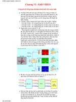
The hardware features of the controller are:
4
1
3
5
6
7
8
9
1
3
4
5
6
7
8
9
3
20142
Input terminals
Mounting hole
Input LEDs
Status LEDs
RS-232 communication channel
Output LEDs
Power supply line power
Ground screw
10
10
Output terminals
2
dc output terminals (or not used)
2
POWER
RUN
FAULT
FORCE
IN
OUT
Preface
MicroLogix 1000 Programmable Controllers User Manual
1–4
Master Control Relay
A hard-wired master control relay (MCR) provides a reliable means for emergency
controller shutdown. Since the master control relay allows the placement of several
emer
gency-stop switches in dif
ferent locations, its installation is important from a
safety standpoint. Overtravel limit switches or mushroom head push buttons are
wired in series so that when any of them opens, the master control relay is
de-energized. This removes power to input and output device circuits. Refer to the
figure on page 1–6.
Never alter these cir
cuits to defeat their function, since serious injury and/or
machine damage could result.
Note If
you ar
e using an external dc output power supply
, interrupt the dc output side
rather than the ac line side of the supply to avoid the additional delay of power
supply turn-off.
The external ac line of the dc output power supply should be fused.
Connect a set of master contr
ol r
elays in series with the dc power supplying the
input and output circuits.
Place the main power disconnect switch where operators and maintenance personnel
have quick and easy access to it. If you mount a disconnect switch inside the
controller enclosure, place the switch operating handle on the outside of the
enclosure, so that you can disconnect power without opening the enclosure.
Whenever any of the emer
gency-stop switches are opened, power to input and
output devices should be removed.
When you use the master control relay to remove power from the external I/O
circuits, power continues to be provided to the controller’
s power supply so that
diagnostic indicators on the processor can still be observed.
The master control relay is not a substitute for a disconnect to the controller. It is
intended for any situation where the operator must quickly de-ener
gize I/O devices
only. When inspecting or installing terminal connections, replacing output fuses, or
working on equipment within the enclosure, use the disconnect to shut off power to
the rest of the system.
Note Do
not contr
ol the master contr
ol r
elay with the contr
oller. Pr
ovide the operator
with the safety of a dir
ect connection between an emer
gency-stop switch and the
master contr
ol r
elay.
Installing
Y
our Controller
1–5
Using Emergency-Stop Switches
When using emergency-stop switches, adhere to the following points:
• Do not program emergency-stop switches in the controller program. Any
emergency-stop switch should turn off all machine power by turning off the
master control relay.
•
Observe all applicable local codes concerning the placement and labeling of
emer
gency-stop switches.
• Install emer
gency-stop switches and the master control relay in your system.
Make certain that relay contacts have a suf
ficient rating for your application.
Emer
gency-stop switches must be easy to reach.
• In the following illustration, input and output circuits are shown with MCR
protection. However
, in most applications, only output circuits require MCR
protection.
Hardware
Preface
MicroLogix 1000 Programmable Controllers User Manual
1–6
The following illustrations show the Master Control Relay wired in a grounded
system.
Note The
illustrations only show output cir
cuits with MCR pr
otection. In most
applications input cir
cuits do not r
equire MCR pr
otection; however
, if you need to
r
emove power fr
om all field devices, you must include MCR contacts in series with
input power wiring.
Schematic (Using IEC Symbols)
X1
230V ac
230V ac
Disconnect
L1 L2
Isolation
Transformer
Operation of either of these contacts will
remove power from the adapter external I/O
circuits, stopping machine motion.
MCR
MCR
MCR
Emergency-Stop
Push Button
Overtravel
Limit Switch
Stop
Start
Suppr.
MCR
(Lo) (Hi)
Line T
erminals: Connect to 230V ac
terminals of Power Supply
.
dc Power Supply
.
Use IEC 950/EN 60950
MCR
+
—
X2
Line terminals: Connect to 24V dc
terminals of Power Supply
.
24V dc
I/O Circuits
230V ac
I/O Circuits
230V ac
I/O Circuits
Master Control Relay (MCR)
Cat. No. 700-PK400A1
Fuse
Fuse
Suppressor
Cat. No. 700-N24
Hardware
Installing
Y
our Controller
1–7
Schematic (Using ANSI/CSA Symbols)
115V ac
230V ac
Disconnect
L1 L2
Isolation
Transformer
Fuse
Operation of either of these contacts will
remove power from the adapter external I/O
circuits, stopping machine motion.
MCR
MCR
MCR
Emergency-Stop
Push Button
Overtravel
Limit Switch
Stop
Start
Suppr.
MCR
(Lo) (Hi)
Line T
erminals: Connect to 1
15V ac
terminals of Power Supply
.
dc Power Supply
.
Use N.E.C. Class 2
for UL Listing.
MCR
+
—
X1
X2
Line terminals: Connect to 24V dc
terminals of Power Supply
.
24V dc
Output
Circuits
1
15V ac
Output
Circuits
230V ac
Output
Circuits
Master Control Relay (MCR)
Cat. No. 700-PK400A1
Fuse
Suppressor
Cat. No. 700-N24
Preface
MicroLogix 1000 Programmable Controllers User Manual
1–8
Using Surge Suppressors
Inductive
load devices such as motor starters and solenoids require the use of some
type of surge suppression to protect the controller output contacts. Switching
inductive loads without sur
ge suppression can
significantly reduce the lifetime of
relay contacts. By adding a suppression device directly across the coil of an
inductive device, you will prolong the life of the switch contacts. Y
ou will also
reduce the effects of voltage transients caused by interrupting the current to that
inductive device, and will prevent electrical noise from radiating into system wiring.
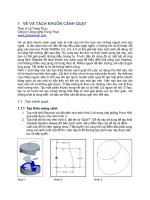
The following diagram shows an output with a suppression device. We recommend
that you locate the suppression device as close as possible to the load device.
OUT
1
OUT 5
OUT 6
OUT 7
OUT 2
VAC/VDC
OUT 0
OUT 3
COM
+
dc or L1
OUT
4
Snubber
ac
or dc
Outputs
dc COM or L2
If you connect a micro controller FET output to an inductive load, we recommend
that you use an 1N4004 diode for sur
ge suppression, as shown in the illustration that
follows.
OUT
1
OUT 5
OUT 6
OUT 7
OUT 2
VAC/VDC
OUT 0
OUT 3
COM
+24V
dc
OUT
4
Relay
or Solid State
dc Outputs
24V dc common
IN4004 Diode
Hardware
Installing
Y
our Controller
1–9
Suitable sur
ge suppression methods for inductive ac load devices include a varistor
,
an RC network, or an Allen-Bradley sur
ge suppressor
, all shown below. These
components must be appropriately rated to suppress the switching transient
characteristic of the particular inductive device. See the table on page 1–10 for
recommended suppressors.
Output Device
Varistor
Output DeviceOutput Device Output Device
RC Network
Surge
Suppressor
Surge Suppression for Inductive ac Load Devices
If you connect a micro controller triac output to control an inductive load, we
recommend that you use varistors to suppress noise. Choose a varistor that is
appropriate for the application. The suppressors we recommend for triac outputs
when switching 120V ac inductive loads are a Harris MOV
, part number V175
LA10A, or an Allen-Bradley MOV, catalog number 599-K04 or 599-KA04.
Consult the varistor manufacturer’s data sheet when selecting a varistor for your
application.
For inductive dc load devices, a diode is suitable. An 1N4004 diode is acceptable
for most applications. A sur
ge suppressor can also be used. See the table on
page 1–10 for recommended suppressors.
As shown in the illustration below
, these sur
ge suppression circuits connect directly
across the load device. This reduces arcing of the output contacts. (High transient
can cause arcing that occurs when switching of
f an inductive device.)
Output Device
Output Device
Diode
(A surge suppressor can also be used.)
—
+
Surge Suppression for Inductive dc Load Devices