KẾT CẤU MỚI FORM AND STRESS MODELLING OF TENSION STRUCTURES
Bạn đang xem bản rút gọn của tài liệu. Xem và tải ngay bản đầy đủ của tài liệu tại đây (2.11 MB, 10 trang )
31
FORM AND STRESS MODELLING OF TENSION STRUCTURES
Michael Barnes
SYNOPSIS
This article gives a brief overview of the development of
form-finding applications for modern tensile roof
structures, particularly CAD methods with stress or
fabrication control of form. Selected projects are chosen
to illustrate the application to cable networks, woven
steel mesh systems, prestressed mechanisms, coated
fabric membranes and air-supported structures. The
purpose is to review the form-modelling of direct force
structures in which the form must physically be a
reflection of the prestress distribution - to provide a
background description, principally for architects who
will work with engineers in the design process.
CONCEPTUAL DESIGN
The origins of the design of modern tensile roof
structures are based on physical modelling techniques,
particularly for the conceptual form-finding process [1].
These physical procedures have ranged, in order of
accuracy, from minimum surface soap films, through
stretch fabric nylon models and the use of specially
formed hexagonal weave models, to the use of silk-
screen fabric (with very low stretch) or uniform mesh
wire models. The latter procedures were sufficiently
accurate for fabrication patterning of simple structures
provided that, for prestressed membranes, the material
used in the real structure had adequate flexibility, or that
boundary turnbuckles were incorporated in cable
networks to adjust tension distributions on site.
A
Fig 1
Fig 2
The most sophisticated design to be carried through to
the stage of fabrication patterning using such techniques,
with precisely measured wire models, was probably the
cable network for the German pavilion at EXPO 67 (Figs
1 & 2), designed by Frei Otto in collaboration with
Gutbrod, Leonhardt & Andrea, and Linkwitz. Whilst
other structures may have been technically more precise
through the use of analytical descriptions for prestressed
shapes, the EXPO 67 pavilion represented a truly free-
form system; and it was perhaps this structure, more than
any other, which captured the imagination of both the
architectural profession and the gneral public and led to
the popularity of tensile structures.
During the design of the Munich Olympic Games
stadium, it became apparent that even quite large-scale
and accurate wire models of the network system could
not be sufficiently precise for design purposes; and since
this time, numerical methods for form-finding, load
analysis and fabrication patterning of both prestressed
membranes and cable networks have played an essential
role in the engineering design process and in the
development of conceptual models
[2,3,4].
32
Fig 3
COMPUTER-AIDED DESIGN
The aim of CAD procedures might be stated as the
replacement of physical modelling techniques by
computer programs enabling realistic graphical display
of form and stress levels and interactive control of these
aspects together with the patterning and detail design
features. An "expert systems" approach incorporated in
these CAD procedures might further provide a guide to
conceptual design, and coupled with CFD procedures
may eventually lead to far better wind load definitions
for complex shapes.
In reality, simple stretch-fabric physical models (Fig 3)
continue to be useful for the initial form studies of
complex free-form systems. In addition to the tactile
value of such models in conceptual design, they provide
a means of communication between various members of
the design team and the best learning process for new
members of a team. They also yield an estimate of
surface curvatures and hence stress distributions and,
when stiffened by a reinforced resin coating, the basis for
wind tunnel model tests. Models may, although now
unusually, also provide a guide to suitable patterning
arrangements and mesh generation topology for finite-
element type analyses. For cable network systems, this
entails the determination of preferred mesh orientation,
generally with a uniform mesh (or grid of equal length
links),
while for prestressed membranes a model clarifies
the choice of panels for fabric patterning - generally
employing "geodesic" seam lines. These geodesies
describe lines that follow a minimum distance over the
surface - equivalent to the trajectories that would be
followed by finite width tapes without shearing
distortion. The geodesic seam lines can thus define the
edges of shear-free panels for fabrication purposes. In
most cases now, only an imagined physical model is
necessary for the definition of an initial computer model.
From an initial definition of topology, CAD procedures
for membranes control the seam geometry to provide
precise cutting patterns with optimum use of material,
the overall structural form being governed
simultaneously by specified stress distributions in the
surface for a weightless prestress state. The neglect of
self-weight in form-finding is important since it allows
the shape to be determined purely on the basis of stress
ratios in the principal weave directions (the warp and
weft of the fabric), with subsequent scaling of stress
levels to satisfy load state design conditions (including
self weight). For fabrication patterning, the
"compensations" that must be applied in the factory
cutting of initially stress-free fabric panels are also
governed by the choice of design prestress levels and the
warp/weft stress ratios, with allowances made for in-
service load distributions and relaxation of the prestress.
For cable networks the CAD process will start from an
initial coarse definition of topology with equal length
links in each net direction (apart from end links
intersecting with curved boundaries). Tension ratios in
each net direction are also specified to cuntrol the surface
curvatures - as with membranes. However, the process is
then usually one of gradual refinement - doubling and
then qudarupling the mesh density - until a net is found
with no untensioned links and sufficient accuracy for
fabrication patterning; "sufficient" meaning that
patterms in a large surface net can be obtained to the
nearest millimetre - steel cables are far less forgiving
than coated fabrics. During all of this process the
topology must be changing, with links disappearing from
boundaries in some regions and new links appearing in
others.
It can be seen from the above description of the
interrelations between form, patterning, design loads and
stress distributions that the use of CAD procedures is an
essential feature in both the conceptual and developed
design stages for tension structures; and that, together
with changes in support geometry and topology, the
specification of required stresses, or forces in discrete
components, is of prime importance in the control of
form.
Fig 4
33
Fig 5
Fig 6
CABLE NET AND UNIFORM MESH
STRUCTURES
The initial form investigations for cable networks and
analysis checks for various load states may often be
based on an equivalent membrane model with
appropriate properties and with one of the cable traverse
directions approximately parallel to the warp (or
geodesic direction) lines in each surface region. A coarse
grid cable-net model may subsequently be numerically
assembled over the membrane surface by choosing one
of the warp lines as a control traverse, from which the
network can be set out link by link until intercepting with
the boundaries. Networks numerically constructed in
this way may be of three types:
(a) uniform grid nets (the most commonly used in
practice);
(b) geodesic nets - since all warp lines in the
membrane surface are geodesies, one set of cable
traverses will be parallel to these lines
throughout the surface and the other set can be
assembled so that angles of incidence onto the
first set are equal to their angles of departure; in
such geodesic nets all cables have constant
tension along their lengths in the prestress state.
(c) hybrid nets in which one set of cables are
geodesies over the surface with equal link
lengths and the other set have constant tensions
throughout their lengths.
Only the third type of net can theoretically exactly fit the
membrane surface - provided that the equivalent
membrane stresses are uniform and equal in all directions
(as a soap fdm model). However, for all three types, the
procedure yields a good starting topology for the net
analysis and its form adjustments.
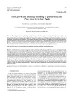
The procedure is closely analogous to the initial
generation of nets from fabric models used for concept
studies. Figure 4 shows a fabric study model (for
Gatlinberg community centre) which was subsequently
fibreglassed for wind tunnel testing (Fig 5). The physical
modelling in this case progressed in parallel with the
numerical modelling which is shown in figures 6-9. In
this coarse CAD model the cable traverse spacings
represent four grids of the real uniform link net and the
colours represent tension levels: light blue or yellow for
the target or low but acceptable tensions, dark blue for
high tensions and red for slack (or buckled) links. At an
early stage in form-finding from an initially flat net the
tensions are rather random with slack or highly stressed
links concentrated in the boundary or mast support areas
(Fig 6).
The first true equilibrium state is shown in figure 7. In
arriving at this state, as much as possible in the CAD
process may be automatic - for example, in short
traverses with shallow curvature the average tension can
be checked and end link lengths adjusted automatically
to meet target values. But for longer traverses with more
complex curvatures, increased stressing at their ends in
an attempt to eliminate large slack areas (see buckled
band in fig 7) will merely over-stress other areas of the
net, particularly around mast supports. In such cases, a
substantial shearing of the net and/or adjustment of mast
configurations is necessary in order to force the slack
bands to follow greater distances over the surface - the
adjusted prestress state, with no slack or over-stressed
links,
is shown in figure 8. After evaluating network
tensions under wind and snow loadings further
adjustments of the form may evidently be necessary; for
example, under snow loading, the tensions around the
hoop and radial support cable ring of the central mast
were too high, and the effective bearing diameter of this
ring was therefore increased (fig 9).
Fig 7
34
Fig 10
Fig 9
The form-finding and analysis of large or finely spaced
networks may be carried out using comparatively coarse
grid models. For fabrication patterning, corrections to
the grid lengths of the numerical idealization must
subsequently be made to allow for local curvatures. This
may be achieved by fitting splines thriough the grid
traverses and shorteneing the slack grid lengths by the
difference between surface arc and chord lengths. The
final stage of patterning involves precise boundary and
mast support zone analyses using a fine grid spacing,
with geometry and tension distributions interpolated
from the overall analysis to set the local zone analyses.
A structure which perhaps more vividly illustrates the
concept of net angle (or shearing) distortions to fit a
surface shape is Munich Aviary (Fig 10). The continuous
surface is formed from butt welded constant width rolls
of crimped stainless steel fine mesh (Fig 11). The wires
are held in place mechanically by the crimping, but allow
in-plane shearing angles of up to 30°. The feasibility of
constructing such a system without wrinkling (and
hence, in this case, parting) of the mesh depends on the
following factors:
(a) the number and height of masts and tie-down
systems;
(b) the number of convex indentations and concave
curves forming the plan boundary geometry (in
relation to the number of masts);
(c) the freedom given, assuming a fixed plan, for
adjustments in the heights of the mesh
attachment along the boundary curve; and
(d) the precise arrangement of the trellis supporting
plates around each mast or tie-down
(Figs 12 & 13).
Fig 11
Fig 12
Fig 13
Fig 14
35
4*
Fig 16
A simple analogy is of laying an open weave cotton net
over a sphere: at the top the net will be orthogonal, but
as the net progresses down the sphere it must shear to
hold to the surface. At a particular depth parts of it must
depart outwards from the surface otherwise it will
wrinkle.
In contrast to the structures reviewed above, the concept
of overlapping shingle plates for the Radolfzell concert
sail dictated that as many plates as possible were
standardized within a tolerance governed by the size of
the clamp bolt holes (Figs 14 & 15). The 0.55m cable
grid was thus arranged to be nearly orthogonal
throughout the surface. To achieve this the surface was
split into regions by means of ridge cables which also
limited deflections and provided security for the main
mast. A similar but more free-form structure was
proposed for the Munich Zoo large cat enclosure (Fig
16).
The orthogonal net orientations for these shingle
structures are clearly dictated by the drainage
requirements. Since the sides of plates are parallel with
the net cables the ideal orientation is at 45° to the steepest
gradient direction, though with a practical tolerance of
±20°.
An alternative which could provide a stiffer
structure, with the net traverses more closely following
lines of principal curvature, would be to orientate the net
at 45° to the plate edges, although perhaps at the expense
of aesthetic appearance. Since the shingles are
physically attached to the net only at opposite corners
this also suggests the use of a hybrid geodesic type net
(type C referred to earlier). A third alternative of a true
principal curvature net is probably impractical from the
point of view of standardization of the cladding panels.
36
Fig 21
The same glazed shingle system as in the Radolfzell
concert sails was used for the undulating wall enclosure
of the German pavilion at EXPO 92 in Seville (Figs 17 &
18).
Again, a major objective was to employ the greatest
number of standard panel units. In this case, however,
there were to be no regional splitter cables; the entire
surface was continuous. Instead of splitting the surface
into regions, two geodesic bands (AA and BB in figure
19a) were employed to induce more equal tensions in the
longer set of traverse cables (inclined at about 30° to the
horizontal). To disguise these "tucks" in the otherwise
uniform network the necessary shortening of the
traverses was spread over three consecutive links in each
geodesic band - figure 19b shows a region of the final
network viewed normal to the plane 123. Whilst the
shingle panels adjacent to the band AA are non-standard,
the great majority of the surface panels are orthogonal.
The main roof of the pavilion was a pneumatic lens
membrane structure 90m x 50m, with an elliptic internal
boundary truss, which was intended to give the
impression of floating over the main assembly / functions
area (Figures 20 and 21). The structure was supported by
a single main mast which, because of its inclination,
allowed the system to be stabilized only by slender
cables (varying from 22 - 42mm 0) attached to the
perimeter of the pneumatic lens (Fig 22). At the base of
the mast the reactions in the self-weight state are
components vertical and horizontal (parallel with the
main axis of the ellipse); the vertical component is
resisted by purely vertical cables around the perimeter,
with greatest tensions in cables at the end nearest the
mast in order to counter the overturning weight. The
horizontal component is resisted by just two cables
(shown thicker in the image), taken from either side of
the lens structure to strong points at the top of the
exhibition building. To accomodate variations in live
load, particularly the lateral components due to wind,
two further cables are taken from these strong points to a
single point at the apex of the lens furthest from the mast;
this arrangement of cables also resists overall torsion of
the structure [5]. In effect the entire system is "docked",
rather analogously to a ship which is moored to a
dockside by fore, aft, and shear lines. A similar principle,
though with more complex structuring, was used in the
design of the Guthrie pavilion in Singapore (Fig 23).
Fig 22
Fig 23 Fig 25
Fig 24
PRESTRESSED MEMBRANE AND AIR
SUPPORTED STRUCTURES
As with cable systems, certain controls in CAD form-
finding of membranes, such as controls on stress
distributions, can be interactive. A very simple example
is shown in figures 24 and 25, in which necking
contraction of a conic is occurring because of insufficient
warp stress (in the radial direction). The system can be
restored to a desired form (Fig 26) by altering the single
parameter of warp line tension to induce increased warp
stress in the necked areas. Other adjustments, for
example of panel and warp orientations, will entail some
resetting of topology - yet this can be established by
specifying only a few principal control lines in each
surface, with automatic interpolation between them. The
colour display of behaviour (Fig 25), form and patterning
(Fig 30), and stress distributions (Figs 35 and 36), are
clearly useful aids to guide the design process. The
display and simple storage of stress contours is important
from an engineering point of view for the comparison of
different load states (and adjustments to form or material
properties). The same graphics routines for stress plots
are also used for contours of height (to examine possible
ponding in shallow areas), or any other variable such as
slope, discontinuity of slope and wind incidence - the
latter to aid load definitions.
The two main entrances at EXPO 92 both employed
widespan cable and membrane shade structures [5]. The
Fig 26
Fig 27
"Diadema", shown in figure 27, employed a porous
fabric partly in order to alleviate the high wind loads on
the structure which had a maximum height of about 55m
and span of 77m. The main surface structure was a wide
grid cable net of equal spacing in one direction and equal
traverse tensions in the other, with the lightly stressed
fabric acting solely as shade covering. The "Oleada"
entrance structure, shown in figures 28 - 31, employed a
more highly stressed heavy-grade fabric, together with
cable reinforcing in the surface whose principal function
was to stabilize the central compression booms.
Fig 28
Fig 29
The design of the Oleada was intended as a continuation
and reflection of La Barqueta bridge which joined the
EXPO site to Old Seville. An initial functional aim of the
structure was to constrain and then open out the view of
the EXPO site. The sculptural form that emerged was
enhanced (Fig 30) by adjusting surface stress ratios and
the positioning and heights of the boundary mast points
so that the surface reflected the motion of a bird in flight
- "Oleada". The membranes span from perimeter guyed
masts to two main central arches of 60 and 70m span, one
inflected downwards and the other upwards. The first
downward arch is suspended and pre-compressed by
cables from 65m high V-form masts, with the
compression force in the arch balanced by ties to the
ground at its free ends. The second, upward arch is pre-
compressed by light ties to ground level with the main
free end thrust in the arch sustained by cables to the top
of the V masts (Figs 29 & 31). In order to decouple the
interactions between these two systems the masts were
additionally guyed by independent cables to ground
anchorages.
Fig 30
39
The original concept for the design was that the two main
arches should be tensegrity type systems - in the sense
that each was to consist of eight pin-jointed slender
compression booms stabilized by spiral cable bracing for
torsional and general stability (Fig 29), assisted by the
mast stay cables or ground ties for stability in the vertical
plane and by transverse cables in the membrane surfaces
to enhance lateral stability. In fact, because of the
complexity and high cost of connection details for the
tensegrity system, and the difficulty of construction in
terms of required tolerances, alternative segmental
arches using thin walled large diameter tubes were
eventually employed. In spite of their sizes (650 and
810mm diameter) they still had a slender appearance (Fig
31).
Fig 32
In a subsequent study [6] the use of fabricated segments
was investigated. Each segment consists of a central
compression boom and three tie rods to either end braced
apart in the centre of the segment by a triangular yoke.
The segments are then prestressed into a pin-jointed
tensegrity arch system using only three continuous
longitudinal chord cables attached to the apices of the
triangular yokes (Fig 32). The advantage of this system
is that only the chord cables (or in fact, for a circular arc,
only one of the chords) need prestressing adjustments,
and the problems of tolerances on site should be
alleviated. However, although the resulting arch is stiff
in bending it has no torsional stiffness - since, in contrast
to the Oleada concept model, there are no spiral bracing
cables. In fact, this is quite acceptable and even beneficial
provided the membranes (or cables within the membrane
surface) act compositely with the arch structure: Figure 33
illustrates the stability of the system under extreme
transverse wind load which induce greatest torsional load.
The yokes twist along the arch and allow the stresses in the
membrane regions on either side to equilibrate eachother.
A more recent project taken to full engineering design by
IPL, though not built, is a very large air-supported structure
for covering industrial waste, principally employed in order
to minimize the cost of contaminated water treatment. This
low-rise structure has a kidney shape (Fig 34) with main
and minor axis spans of 500m x 280m and was to be
fabricated in very heavy-grade PVC polyester in
standardized 20x20m panels with mechanical joints. The
high strength of the fabric eliminates the need for a
reinforcing cable grid, which otherwise would have to
sustain the main spanning tensions because of the disparity
between membrane and cable stiffnesses (particularly with
longer term effects). In addition to its strength the
membrane has very high visco-elastic damping which is of
benefit in terms of dynamic behaviour. However, this also
entails substantial creep, particularly in the weft direction
of the material. A major aspect of the design and associated
material testing was therefore to account for both first time
loading elastic stiffnesses and long-term creep effects in
order to ensure a reasonable degree of load sharing between
warp and weft fibres under various load states - figures 35
and 36 show contour plots of warp and weft stress for one
wind loading direction.
W
Fig 33
Fig 34
Fig
36
Another important consideration
in the
design
of
very wide
span air-supported structures
is the
question
of
dynamic
stability. High-rise structures with greater curvatures
may
have potentially lower membrane stresses
but are
likely
to
be subject
to
non-uniform, shape-deforming distributions
of wind pressures
and
suctions.
In
contrast, low-rise
systems
are
likely
to
have much more uniform wind
suctions over
the
entire surface,
but
higher tensions will
be
induced because
of the
shallow curvature. Although these
higher tensions incur penalties
in
terms
of
foundation loads
they significantly improve large scale dynamic stability.
A
greater problem
for
these large scale air-supported
structures
(and
other shallow membrane systems)
is
snow
loading
and the
potential occurrence
of
ponding
and
consequent failure. This
has
been
a
difficulty with several
of
the
largest built structures
of
this type
and is
perhaps
the
reason
for the
reduced
use of
air-supported systems
in
recent years.
An
alternative view
is
that control systems
and
the
means
of
modelling wind
and
snow loadings
and
their interaction with structural systems have
now
substantially improved. These aspects
are
considered
in the
final
two
papers
of
this section
on
form
and
structure.
ACKNOWLEDGEMENTS
Consulting Engineers
for the
Gatlinberg Centre project
and
for
Munich Aviary were Buro Happold.
The
Architects
for the
former were Sprankle Lynd
and
Sprague
and for the
latter
was
Jorg Gribl. Frei Otto
was
Consultant Architect
for
both projects.
Consulting Engineers
and
Architects
for all
other projects
illustrated were
IPL
under
the
direction
of the
late Harald
Muehlberger.
REFERENCES
1.
Frei Otto: Tensile Structures,
MIT
Press
, 1971
2.
Haug,
E,
Powell,
G H:
Finite element analysis
of
non-linear
membrane structures, IASS Symp.
on
Tension Structures
and
Space Frames, Tokyo,
1971
3.
Argyris,
J H,
Angelopoulos,
T,
Birchat,
B: A
general method
for
the shape finding
of
lightweight structures,
Int. Conf. on
Tension
Strucrtures, London,
1974
4.
Barnes,
M R:
Applications
of
dynamic relaxation
to the
design
and analysis
of
cable, membrane
and
pneumatic structures. Second
Int.
Conf. on
Space Structures, Guildford,
1975
5.
Barnes,
M R,
Renner,
W,
Kiefer,
M:
Case studies
in the
design
of widespan EXPO structures, Proc. Conceptual Design
of
Structures, Stuttgart,
1996
6. Adriaenssens,
S,
Barnes,
M R,
Mollaert,
M:
Deployable torsion
free tensegrity spines, Proc. Engineering
a New
Architecture,
Aarhus,
1998