KẾT CẤU MỚI CONTROLLING THE INDOOR CLIMATE IN WIDE SPAN ENCLOSURES 4 CASE STUDIES
Bạn đang xem bản rút gọn của tài liệu. Xem và tải ngay bản đầy đủ của tài liệu tại đây (1.68 MB, 10 trang )
117
CONTROLLING THE INDOOR CLIMATE
IN WIDE SPAN ENCLOSURES
4 CASE STUDIES
Nick Cullen
Hoare Lea & Partners - Consulting Engineers
SYNOPSIS
This paper presents four case studies of different large
span structures, describing the characteristics of, and the
systems used to control, the indoor climate.
The first two studies consider the difficulties inherent in
designing systems that 'fight' against the basic laws of
physics. The first of the two, the British Aerospace
Aircraft Assembly Hall is based on work undertaken in
the 1980's and highlights the significance of buoyancy
forces and the difficulty in mixing airstreams of different
temperatures. The second case study, the ExCel
exhibition centre in London's Docklands, highlights the
need for compromise in the design of Engineering
systems.
The second two studies review projects in which the
designs made use of the natural forces of gravity and
buoyancy in order to maintain thermal and Indoor Air
Quality (IAQ) conditions. The first, the Millennium
Stadium
Cardiff,
features a fully retractable roof and
relies upon Natural Cooling and Ventilation enhanced
with the operation of the smoke extract fans as necessary.
The final Study details the work undertaken at the House
of Representatives, Brasilia the Capital of Brasil. It
discusses the significance of control and alternative
strategies.
INTRODUCTION
To the Building Environmental Engineer it is generally
not the overall size of a building that creates the
challenge it is the internal height and the lack of suitable
locations for indoor climate control systems. Large span
structures are synonymous with high open spaces.
The Engineer seeks to control not only thermal
conditions but also Indoor Air Quality (IAQ) both to
achieve comfortable conditions within the occupied
space and to maintain a healthy environment free from
pollutants (of which there are many). Ideally the
Engineer would seek to condition the occupied space
rather than the whole volume and hence benefit from
both reduced plant capacity and reduced energy
consumption and C0
2
emissions. This is not always
possible.
The temperature within a large space can be controlled
using air systems or radiant systems. Indoor Air Quality
(IAQ) can only be controlled using 'fresh air' (usually
outdoor air). Many systems tend to combine the
temperature regulation function with the IAQ function.
The problem faced by Engineers is that hot air rises, or
more accurately, cold air falls and forces warmer air to
high level leading to temperature stratification within the
space. This fundamental law of physics can work to the
Engineers advantage. A case in point being Displacement
Ventilation Systems (natural or mechanical), which rely
upon buoyancy and gravity forces to drive them.
However displacement air systems require the supply air
to be introduced at low level and at regular -albeit fairly
large -intervals. This is rarely compatible with the needs
of large span structures and indeed is often in conflict to
the use of such structures.
The consequences of stratification are twofold. Firstly,
the increased temperature differential at roof level results
in a greater heat loss increasing energy consumption and
thereby C0
2
emissions. Secondly, thermal conditions
within the occupied zones may at times be unsatisfactory,
depending of course, on the location of the occupants.
High spaces are generally conditioned using mixing
systems with the supply air introduced at high level, the
objective being, to minimise stratification by producing a
fully mixed environment. The designer has to ensure that
when heating the supply air can deliver heat to low level
and when cooling the air arrives at low level without
causing discomfort due to cold drafts. In the process of
creating a mixed condition, pollutants, produced within
the space, are diluted by 'fresh' air.
The alternative, that of displacement ventilation, seeks to
condition and removes pollutants only from occupied
zone.
118
CASE STUDY NO.l
BRITISH AEROSPACE AIRCRAFT
ASSEMBLY HALL, BRISTOL
"THE BRABAZON HANGER"
BACKGROUND
The aircraft assembly hall was constructed
in
the 1940's
for
the
specific purpose
of
constructing
the
Brabazon
aircraft, the largest aircraft
in
the world
at
the time.
The
building's clear height (23m)
was
determined
by the
height
of
the Brabazon tailfin and
its
clear internal span,
by
its
wingspan. Its overall internal height reaches 35m.
At the time the building was completed,
it
was one
of
the
largest clearspan structures
of
its type
in the
world.
Its
floor area was approximately 30,000m
2
and
enclosed
a
volume
of
1,000,000m3
(Figures 1&2).
Height to Eaves
26 m
Height
to
Apex 35
m
Floor Area 30,000
m
2
Total Volume
1
mi
1.1
ton
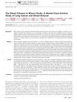
Fig I The Brabazon Hanger - Exterior View
Fig 2 The Brabazon Hanger - Interior View
EXISTING HEATING SYSTEM
The original (1940's) heating system comprised steam
unit heaters
at
catwalk level blowing
air
vertically down
into the space. At the perimeter
of
each bay were located
a row
of
"swan neck" steam heaters which drew cool
air
from
low
level, heated
it, and
discharged
the
warm
air
down towards
the
hangar floor from
a
height
of
about
10m (Figure
3).
By
1980
the
steam pipework
was
beyond
its
useful life
and had
significant leakage
problems.
The
pipework
was
poorly insulated, mainly
with asbestos and as
a
consequence, apart from the health
issues
of
asbestos the operating efficiency
of
the system
was extremely poor. Furthermore, under test
it
was
found that
the
unit heaters
at
catwalk level gave
insufficient velocity
to the hot air to
overcome
its
inherent buoyancy.
The
heated
air
lost
any
momentum
after the first few metres and rose back
up to
high level.
Thus,
only
the
perimeter "swan neck" heaters provided
any useful heat
to the
hangar floor,
the
remaining
capacity being used to heat the roof space. Temperatures
at roof level rose regularly towards 40°C
in
the
vain
attempt
to
hold
a
comfortable temperature within
the
occupied zone (Figure 4).
He,!
Lot*
through Roof
Down draught heaters
dine!
airdowtw>nry3m
Swan Neck Darcharge
CROSS
SECTION -CENTRE SPAN)
Fig 3 Existing Heating Sytem
Improved thermal performance
Reduced heat
Ion
leading to increase tn
temperature
CROSS SECTION -CENTRE
SPAN)
ORIGINAL ROOT
4
HEATING
SYSTEM
CROSS SECTION -CENTRE
SPAN)
NEW ROOF
4
HEATING
SYSTEM
The building has always been difficult to heat effectively.
In the early 1980's
a
complete re-cladding
of
the building
was undertaken
to
upgrade
the
performance
of the
building envelope
to
comply with
the
Building
Regulations standards
of
the day.
Sadly,
the
cost
of
upgrading the doors was prohibitive,
a
feature which
we
will return
to
later.
Fig 4 Temperature Profiles
NEW HEATING SYSTEM
Immediately following
the
recladding contract, Hoare
Lea
&
Partners were commissioned
to
design
a
new
direct
gas
fired heating system
to
replace
the
original
steam fired system.
The
concept
was
to
replace
the
119
existing steam heaters at catwalk level with direct gas
fired unit heaters, blowing vertically downwards from a
height of 23m (Figure 5). The existing perimeter heaters
were to be modified, and instead of blowing warm air
down to low level, they were to draw cool air from low
level and to discharge the air vertically upwards, mixing
the cool air with warm air at high level, inducing
destratifying circulation currents within the space.
CROSS
SECTION -CENTRE SPAN)
MODIFIED HEATERS
Fig 5 Proposed New Heating System
The concept had been developed in conjunction with Bristol
University who carried out performance monitoring on the
existing system and then on a trial mock up, modifying one
of the perimeter "swan neck" heaters. Initial results were
promising, showing a much reduced temperature gradient in
the space.
The team identified the proposals as carrying significant,
technical risk, there being no precedent for use of reverse
destratification system, least of
all,
on a building of this size.
In order to offset this risk, the team applied to the EEC for a
Thermie Grant which was subsequently awarded, in
recognition of the innovative nature of the project.
The client embarked on a significant construction contract,
comprising the removal of the existing heating system,
including the steam pipework installation, asbestos
insulation and heaters. In its place was installed a new gas
pipework, new power distribution system, fan powered unit
heaters complete with discharge jet nozzles. The complete
installation was undertaken, at a height of 23m, whilst
maintaining production on the factory floor. This required
significant protection measures to be provided to allow the
building occupants to continue working safely. Key design
considerations involved reducing C0
2
, and moisture levels
in the space to acceptable levels by introducing fresh air
through perimeter units. The design of the heaters, and
"swan neck" discharge nozzles was also critical to give good
air mixing and air distribution.
The designers struggled to balance the design parameters of
heat input, air velocity, noise and power consumption and
cost and eventually arrived at a "best fit" solution.
PERFORMANCE
After completion of the installation, the performance of
the heating system was monitored to assess whether the
predicted performance was achieved in practice. The
results were dramatic.
The delivery of air at 45°C to the hangar floor from a
height of 23m required a substantial discharge air
velocity. At part load conditions, when the discharge
temperature was lower, the high discharge velocity was
not dissipated, so that a very high air movement occurred
at low level. It was decided to accept a restricted
turndown ratio on the units, typically to a minimum of
80%
of full heat output, the fans being controlled
"on/off below this level.
The building fabric, and particularly the old hangar
doors,
were found to allow a considerable amount of cold
air to infiltrate into the building. As a consequence of the
density of this cold infiltration, it tended to collect at low
level creating a cold "lake" of air at about 10°C in the
first 2m above the hangar floor, the very zone that was
required to be heated.
Under full load output from the heaters, operating in
response to temperature sensors located in the cool
occupied zones, the buoyant warm air was found to have
lost most of its momentum by the time it arrived at the
bottom 2m zone. The discharge air suddenly moving in
10°C set, not 20°C ambient air, effectively "bounced" at
this 2m level, providing very little heating effect in the
occupied zone. As a consequence, the whole volume of the
hangar was being heated to a temperature of 20-25°C, in
order to maintain I0°C in the occupied zone (Figure 6)!
^t^+HMt Low through Roof
, ""1
a Entrained Air item high lev el mixes '
20*C
t§
With
raster
dBchtrge
Air
CROSS
SECTION-CENTRE SPAN)
Fig 6 Actual Performance
MAIN ACCESS DOOR
Paradoxically, the solution to this problem was to reduce
the maximum heat output of the gas heaters, lessening
the buoyancy of the supply air, which enabled proper
penetration by the supply air into the occupied zone, and
good mixing in that space.
120
The modified "swan neck" destratification units were
found to have minimal effect in destratifying the space,
the temperature profiles and airflow patterns being
determined primarily by the velocity and discharge
temperature of air from the direct fired gas heaters.
Of course with hindsight the solution should have
included:
(i) an increase the thermal performance of the
doors
(ii) a reduction in the infiltration leakages of the
building.
Had it been practical within the constraints of an
operational production facility, the provision of a warm
floor by embedded piping or by overlaid radiant heaters,
may have overcome many of the problems.
CASE STUDY NO.2
EXCEL LONDON, ROYAL VICTORIA
DOCK
INTRODUCTION
Across the river from the Millennium Dome on the North
side of the Thames a New "State of the Art" exhibition
centre is about to open. Phase 1 of the project will
provide 93,500m
2
of accommodation including 64,000
m
2
of exhibition space split between two halls. Each hall
is designed with a minimum clear height of 10m. The
entire exhibition space is located above a car park. A
boulevard running the length of the building separates
the two column free halls. The whole building can
operate as a single exhibition space or be sub-divided
down into individual halls each of 4000m
2
(Figure 7).
Fig 7 Excel Exhibition Centre - London Docklands
VALUE MANAGEMENT
The indoor climate control system was divided according
to the minimum module size. A single air-handling unit
serves each module and is located at high level within the
structural depth of the
roof.
Supply air ductwork from the
air-handling unit is distributed at high level (Figure 8).
Out door air is drawn in via a 'beehive' air intake the
amount being determined either, by Indoor Air Quality
(IAQ) as measured by CO
z
sensors, or according to the
free cooling opportunities. As extract air is drawn it
passes directly from the space and discharges to out
doors.
Intake Air
Exhaust Air
^s-—
.,.,••„-
)IINI?jahu|
••••• "7—\
Supply Air via Long throw Diffisers
EzUbitlonHal]
I Clm
r
Boulevard
Supply Air via Long throw Diffisers
EzUbitlonHal]
I Clm
r
90m
Fig 8 Excel Exhibition Centre - London Docklands - Diagramatic
121
The exhibition space required both cooling and heating.
The supply air system therefore had to operate to deliver
warm buoyant air to low level during heating, and cool
non-buoyant (heavier) air during cooling. The obvious
answer was to vary the trajectory of the supply air
according to the supply air temperature by using
adjustable geometry diffusers. This however proved to be
too costly and would probably prove to be unreliable and
an alternative approach was required.
The alternative proposal envisaged a fixed airflow
trajectory with long throw nozzles fixed directly into
ductwork and arranged in groups. With volume flow rate
and design supply air temperatures, fixed, two variables
remained under the designers control, discharge velocity
and trajectory (Figure 9). Using Computation Fluid
Dynamics combinations of the different parameters were
tested in both heating and cooling modes.
Computational Fluid Dynamics, not available at the time
the design of Brabazon Hanger Design was employed to
assess options and performance of the design (Figure 9).
RESULTS
The results from the analysis showed that the cold slab
(due to the unheated car park below) would create a
'lake'
of cold air at low level which could be reduced in
depth by increasing the momentum of the supply air, but
could not be completely overcome. Once again the
conclusion pointed to the need for a warmed floor which
was beyond the budget. (Figure 10).
The CFD modelling images brought instance 'Deja vu' to
the (by now Partner) engineer who years earlier had
experienced the Brabazon hanger or refurbishment and
its outcome.
It was recognized that the primary circumstance likely to
occur was that of cooling and so parameters were
selected to satisfy the associated thermal comfort
conditions.
Engineering designers learn very early that compromise
will be called for, that compromise often involves
designing to satisfy the primary circumstances. When
warmth from exhibits and people will require a cool air
supply from the building systems. That lessens the
outstanding probability that when a few people rent a
small amount of the space in colder weather they may
find a bracing experience requiring a pullover. Satisfying
the majority that is now called value judgement and is an
essential part of an engineer's experience.
Figure L5 (a) Temperature
distribution at
height of
1
5m
Fig 9 Results - Computational Fluid Dynamics
23B
Winter
model,
no occupancy Winter
model-
Low
level
occupancy
Fig 10 Results - Computational Fluid Dynamics
122
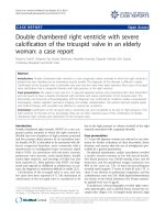
Fig
11
Millennium Stadium Cardiff
-
Exterior View
CASE STUDY
NO.3
THE MILLENNIUM STADIUM CARDIFF
INTRODUCTION
The £120million Millennium Stadium Cardiff
has a
capacity
of
72,500 people
and is the
first
UK
arena
to
have
a
fully retractable
roof. It
provides
a
multi-use
all
weather venue with completely un-restricted views.
The
grass pitch
is
completely removable allowing
the
arena
to
be
put to use as a
concert venue.
The
stadium takes
the
form
of a
bowl complete with retractable
roof.
This form
Fig
12
Millennium Stadium Cardiff
-
Interior View clearly limits
the
Natural ventilation
and
cooling
mechanisms that
act
around stadia with open corners.
The retractable roof (Figure
11 & 12),
when closed,
created
a
number
of
problems that
the
designers needed
to resolve. Firstly
the
space needed
to be
ventilated
to
remove unwanted heated
and
metabolic pollutants.
Ventilation
was
also
an
important factor
in
maintaining
a
healthy grass pitch. Secondly
it had to be
safe, allowing
spectators
to
escape
in the
event
of a
fire.
123
The arena was conceived
as
being Naturally Cooled
and
Ventilated using
the
vomitory passage ways
and a
high-
level louvre system
as air
paths. Numerous different
scenarios were considered using Computational Fluid
Dynamics (CFD).
The
Criteria
set for the
Stadium
was
for
all
occupied areas
to
remain below 28°C
at
design
summer conditions (26°C).
The
effect
of
different sized
openings, their number
and
location were investigated.
The initial analysis assumed
a
worst-case scenario
of
stack driven ventilation only without wind assistance.
The analysis showed
the
need
for two
sets
of
parallel
louvres running
at
high level
, one at the
junction
between
the
retractable roof
and the
fixed roof
and the
around the back
of
the upper tier seating. Temperatures
at
high level varied only slightly between
the
various
options (Figure 13). The arrangement operated primarily
using Natural buoyancy effects
and,
when available,
wind pressure
to
drive
air
through
the
arena.
The
smoke
extract fans
are
made available
to
guarantee
a
minimum
volume
of
fresh
air
movement through
the
arena.
CFD modelling showed that the combination
of
vomitary
and high level openings produced acceptable conditions
with the roof closed even without the beneficial effects
of
wind
or
with
the
fans running.
&
PARTNERS
26 0
Cardiff
Millennium
Stadium
Fig
13
Results
-
Ventilation
and
Cooling CFD Results
FIRE
The fire engineering
for
public arenas
is
vitally
important.
The
objective
was to
determine whether,
in
the event
of a
fire, there would
be
sufficient time
for the
audience to escape. This time
for
full evacuation from the
arena
was
calculated
as 12
minutes taking into account
detection, investigation, action
and
evacuation times.
In
addition
a
smoke temperature limit
of
200°C
and a
visibility distance
of 25m to a
reflective sign were
adopted,
as
design criteria.
Being primarily
a
sports stadium
the
potential fire load
was minimal.
It
was considered that
a
pop concert with
a
stage located
at
one
end of
the pitch
was the
worst case
scenario.
The
effect
of the
operation
of the
mechanical
extract system
was
investigated using Warrington's Fire
Research CFX CFD software.
The results highlighted two important factors. Firstly that
the depth
of the
smoke
was
worst
at the end of the
stadium closest to the fire (Figure 14). The time available
for escape
in
these areas
did not
meet
the
design criteria
and people could
not be
located
in
these areas.
Secondly the operation
of
the fans provided
an
additional
2 minutes escape time extending the period to 14 minutes for
the topmost seats. The extract temperature
of
the smoke was
estimated
as
being between 39°C and 43°C, well within the
operational capability
of
the fans (Figure
15).
Time:
+12
minutes
_
0.0010
0.0000
Fig
15
Computational Fluid Dynamics
-
fire/smoke
-
fans
operational
Fig
14
Computational Fluid Dynamics
-
fire/smoke
- no
fans
124
CASE STUDY NO.4
HOUSE OF REPRESENTATIVES,
BRASILIAN CONGRESS BUILDINGS,
BRASILIA, BRASIL
In late 1997 Hoare Lea & Partners Research and
Development group were asked to offer advice on the
problem of acute 'Sick Building Syndrome' in the House
of Representatives at the Brasilian Congress. The
particular Building, is that pictured and constructed in
the 1960's to designs by the renowned Architect Oscar
Niemeyer (Figure 16).
Fig 16 House of Representatives, Congress Building, Brasilia -
Exterior View
The House of Representatives is one of two chambers
(plenaria) in the Congress building complex and it measures
some 30 m in diameter and 15m high. The plenaria has
capacity for up to 550 people made up both of Representatives
and a smaller number of journalists. A raked gallery for
'spectators' overlooks the chamber, encompassing
3
/
4
of the
high level perimeter, but this is isolated from the chamber by a
glass screen (Figure 17 & 18).
Fig 18 House of Representatives, Congress Building, Brasilia -
Interior View towards Podium
The building had been reported as 'sick', indeed a
Government Minister had passed away it was said,
"because of the amount of his time he had spent in the
building". An initial visit and inspection of the air supply
system indicated that the system was clearly at the end of
it's serviceable life. It also had some inherent design
problems most notably the absence of any system of air
extraction other than by tortuous route out of the
chamber via the main entrance doors which had to be left
open. (Figure 19).
Fig 19 House of Representatives, Congress Building, Brasilia -
Schematic representation of existing ventilation and cooling
system
Hoare Lea and Partners were asked to put forward a
scheme which after much consideration was based on
Displacement Ventilation principles. Unlike the first two
case studies displacement ventilation is a system that
relies upon natural forces to function. Cool fresh air is
introduced at low level and is drawn towards any heat
source where is warms and is 'displaced' to high level
taking with it unwanted heat and pollutants. The polluted
air can be extracted and thrown away having first passed
through heat exchangers.
Fig 17 Plan and Section through House of Representatives
Two alternative schemes were studied and each was
modelled using Computational Fluid Dynamics. The
favoured scheme envisaged the installation of a
compartmented raised floor through which air would be
delivered to air terminals integrated into the seat. The
floor would double as a conduit for power and data
cabling (Figure 20).
Schematic of Proposed New
Displacement Ventilation for
dulled AHeattng Water from Existing Central Plant
-
Fig 20 Schematic of proposed new displacement ventilation
The alternative method was to introduce the air around the
perimeter of the space a scheme that would have required
only a small raised platform.
The size of the space highlights another inherent problem of
large spaces not so far mentioned, that of locating control
sensors. This problem exists irrespective of the parameter
being measured.
Ideally the sensor should be located at regular intervals
within the occupied zone, but without a surface on which to
mount the sensor an alternative strategy is required. The
walls around the chamber offered possible locations but were
rejected due to their variable surface temperature and
unrepresentative location.
The main concern was the IAQ within the space and the
main pollution sources both of heat, chemical and biological
contamination were the occupants themselves. The quantity
of air could therefore be varied according to the number of
occupants within the space. Whilst C0
2
sensors are regarded
as a good measure of IAQ when people are the main
pollutant source, they were considered to be too much of an
on-going maintenance item requiring regular re-calibration.
Two alternative strategies were conceived. The first was the
inclusion of a variable volume damper within the
construction of the seat
itself.
This would enable the
associated diffuser to deliver fresh air only when the seat was
occupied. A background supply would be guaranteed
through other diffusers. The alternative was simply to count,
electronically the number of people within the space and
then deliver an appropriate volume of fresh air. This would
rely upon the characteristic of displacement ventilation for
the air to be drawn to the heat sources within the room. Both
these options would have resulted in energy and C0
2
consumption reductions.
Ka il.aii loi'iKc&t
-
under Lest tolut>
.
•.
• i . ->' - of
Temper&l'j'e
tl)
Fig 21 CFD Results - Velocity Vectors - Temperature Supply
Riri/'iian Conor Case 2S
Vekioty Victors Gotwrt C> Vckc-oty Magn-tuOo
(nvs)
RMHAJNS
4.2 pa to
i
:
Thu
Apr
te-W8
;
Fig 22 CFD Results - Velocity Vectors - Perimeter Supply
Rrf.7t»u*nCuiiti(e** C&ce
2»
Vei»:*v Victors Ccwaoa Dv V**fflv Magirtudo
(m/s)
Cioss section
at
tortus
• 20m
eiuonfUNS
4.2
0(1.
he)
Thu Ap» 16 -aSK)
Fluefil
inc.
Fig 23 CFD Results - Velocity Vectors - Perimeter Supply
B'tU'haii
Cu
tyieu Cass
1
••'-•>:•< V6CKHSCokxM
r. .e. • "
Cress
free
non at
racJus
-
25nt
E
H«1H.
:
NS4.2(3J M»2.W. unstMQY
Fn Apt 17 1998
Hurt
IK,
Fig 24 CFD Results - Velocity Vectors - Under Seat Supply
126
RESULTS
The results confirmed the design supply air volume was
sufficient to maintain thermal conditions within
acceptable limits in both cases (Figure 21). It did
however identify that the alternative perimeter supply
solution generated a 'dough-nut' vortex which had the
effect of driving high level polluted air to low level back
down into the occupied zone. This was due to three
factors. Firstly the massing of heat sources created a
coalescence of individual plumes which rose to high
level. Secondly the thermally cool surfaces of the glass
divide between the gallery and plenaria generated a down
flow of air. Thirdly the rising plumes of air drew air from
the perimeter supply points. The combination of these
three characteristics generated the vortex (Figure 22 &
23).
In contrast the favoured option with the supply air
introduced on a seat by seat basis showed a less vigorous
air movement with a general, albeit un-steady drift of air
flow to high level (Figure 24).
The project proposals await approval and finance from
the government which, unlike our own, of whatever
party, is very concerned not to spend money on it's own
accommodation whilst there are calls for money from its
populace.
CONCLUSION
Wide span structures enclosing large volume high spaces
present the Building Engineer with significant
challenges. The Building Environmental Engineer seeks
to control the conditions within the occupied space with
the minimum of 'environmental impact'. Numerous
different scenarios often need to be considered The
function of the space along with cost restrictions often
force the Professional Engineer to design systems that
fight the basic laws of physics and to seek compromises
in performance. The advent of CFD has given the
Engineer an invaluable tool enabling the prediction of the
performance and comparison of different engineering
systems. Despite the rapid growth in computer power we
are still limited to making only global assessments of
large spaces.