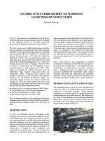
KẾT CẤU MỚI SERVICING THE DOME ENVIRONMENT
Bạn đang xem bản rút gọn của tài liệu. Xem và tải ngay bản đầy đủ của tài liệu tại đây (1.31 MB, 8 trang )
137
SERVICING THE DOME ENVIRONMENT
Tony McLaughlin BSc. C Eng. MCIBSE. MASHRAE. M Inst E.
Partner, Buro Happold Consulting Engineers
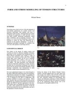
SYNOPSIS
The Millennium Dome is a fabric clad structure covering
some 80,000m2 which is to house a spectacular
exhibition for the duration of the Millennium Year. This
paper describes some of the constraints on the
environmental engineering design, the servicing strategy
adopted, the cooling and electrical loads determined, and
how the environmental design evolved to meet the
changing development of the exhibit designs.
INTRODUCTION - THE MILLENNIUM
EXPERIENCE
The idea of holding a celebration for the millennium had
been talked about since 1993 and even before. The
Greenwich site had always been a possibility but other
sites were also under consideration. In the latter part of
1995,
the Millennium Commission invited bids with
design proposals for several sites. Imagination Ltd
joined with the NEC and Birmingham City Council to
put forward a proposal for Birmingham. Buro Happold
assisted Imagination in that bid. Imagination's proposal
for content and design ideas was judged the best and they
were subsequently asked to consider how they would
transfer it to Greenwich. In the first months of 1996,
Imagination, with assistance from Buro Happold, put
forward a number of proposals for housing an exhibition
in pavilions with a large arena for shows and displays.
Richard Rogers Partnership was at that time working
with British Gas and English Partnerships on the master
plan for the whole of the gas works site. Their master
plan had a circular road pattern at the northern end,
which Imagination had incorporated into their exhibition
plan.
The separate pavilions were four generous storeys high
and involved a considerable amount of construction work
leading to a difference between the costs of the designs
produced by Imagination to meet the
brief,
and the
Millennium Commission's budget. The site was very
exposed to wind and rain coming off the river and there
was a worry about the impact of this on visitor
experience in the winter months. Imagination was trying
to deal with this by covering the spaces between the
pavilions, which were arranged around a central show
arena.
In May 1996, faced with time running out, Gary Withers
of Imagination and Mike Davies of the architects Richard
Rogers Partnership suggested covering the whole site
with a giant umbrella. This would create a protected
environment in which exhibition structures could be
designed specifically for the exhibitions and be rapidly
erected without the necessity for weather tight cladding.
We in Buro Happold picked up that idea and suggested a
fabric clad stressed cable-net structure supported by 12
masts.
This concept was welcomed by the client and
engineering work got underway.
THE SITE CONDITIONS
Greenwich peninsula is an exposed site with the river
Thames on "three sides "of the Dome site leaving it
vulnerable to the winter winds from the east. In the depth
of winter it can be an inhospitable place when the wind
is in the wrong direction. Mike Davies reminded us many
times that to the east there is no ground over 100m
between Greenwich and the steppes of Moscow. But like
most southerly UK sites the met office offers the
following synopsis, the prevailing wind is south westerly,
the coldest month is January with a mean monthly
temperature of 4oC and July is the warmest month with
a mean monthly temperature of 17.5oC. As a matter of
interest a temperature of 37.8oC was recorded at
Greenwich in 1911. Greenwich is 7m above sea level.
ENVIRONMENTAL ENGINEERING
THE 'UMBRELLA' CONCEPT
The concept of developing an "umbrella" environment is
nothing new, as many of the mainline rail stations
demonstrate. What makes the Millennium Dome
different is its physical scale and its intended purpose.
The dimensions of the Dome are huge: 320m in diameter,
50m high in the centre, with an enclosing wall structure
10m high and 1km long. The contained volume is
approximately 2.1 million cubic meters, which leads to a
many well published and interesting statistic eg the
weight of air inside the Dome is actually greater than that
of the structure that encloses it, not to mention the fact
that it could contain 3.8billion pints of beer It is twice
the size of Atlanta's Georgia Dome, previously the
largest tensile-roofed structure in the world.
138
•mm
U
Fig 1A The Environmental Concept
4
320m
w>
Fig IB The Problem of Scale
Solar
Reduction
The
Creation
of a
Meso
Environment
under
the
Dome
roof from
which
other
structures
(core
&
exhibition
buildings)
can
spawn.
FiglC
design
and
passive control systems: mechanbal control systems:
• protection from solar radiation
in hot
weather
•
fresh
air
ventilation
• protection from precipitation
in wet
weather
• air
movement
• natural ventilation
in hot
weather
•
heating
in
winter
• wind protection
in
cold weather
•
comfort cooling
in the
core
•
a
smoothing
of
temperature
or
humidity accommodation
and
exhibits
Fig ID
When
we
first started work
on the
building services
and
environmental systems,
it is
fair
to say
that
the
Clients brief
was somewhat lacking, both
in
terms
of what
was likely
to
happen inside
the
Dome,
and
even more
so,
what
its
form
and operation
was
likely
to
be.
The
driving issue
was
time.
The only design guidance
we had, was to
draw
on our own
previous experience
and
look
at
precedents.
The
idea was
to
provide
a
services back bone which would give
the
desired
flexibility
for an
exhibition theme which was still very much
in the melting pot. Naturally this flexibility would also have
to have
the
capacity
for the
likely energy demands
of the
future exhibitions, all of which would be unique. At the time,
Imagination were leading
the
team,
and it was
with their
extensive knowledge of past and present exhibitions,
as
well
as
a lot of
research into utility loads
for
existing exhibitions
that
we
established
the
following energy demands:
Power supply 35MW
Cooling demand
18MW
Heating demand 2.5MW
for the
Dome
air
intake systems.
How these were delivered
is
addressed later
in the
paper.
ENERGY BALANCE
Initially,
one of
the design team's primary concerns
was the
environmental implication
of
putting such high heat loads
together with 35,000 visitors under
a
transparent
roof.
What
were
the
environmental conditions likely
to be
experienced
by
the
visitors? What would visitors expect? Would
conditions
be
acceptable?
The roof
is a
double skin fabric, which allows
12%
light
transmission
and has a
shading coefficient
of 0.08.
Externally,
the
fabric
is
highly reflective (white), whilst
internally
the
fabric
is a
white "matt" finish. Initially,
the
architects
and
cost consultants preference
was for a
single
skin structure
but
this
had to be
rejected environmentally,
due
to the
need
for
increased solar protection
of
the double
layer
and,
just
as
important,
the
need
to
provide some
thermal insulative properties
for the
winter conditions.
The
convincing argument
was the
much-reduced risk
of
condensation.
The
inner fabric liner
-
which
is not
structurally taut as the outer layer - also assists in "softening"
the enclosure's acoustic characteristics.
The following energy balance diagram
was
first used
to
illustrate
the
problem
and was the
first simple step
in our
environmental analysis
of
the Domes environment.
One
of
the underlying design objectives
for the
"umbrella"
environment was that
it
should
use the
niinimum amount
of
energy to provide the transient environment within which the
exhibition would operate. Another advantage
of the
"umbrella"
is
that
it
allowed
the
construction
of the
exhibition
and
core buildings under cover, free from
the
extremes
of
the British climate.
The
downside
of
this latter
point
was
that construction dust
etc was
trapped which
eventually stained
the
inner liner.
Fig 2 Energy balance diagram
CONDENSATION
The thermally lightweight, low insulation, high occupancy
characteristics of the Dome did give the design team some
concerns regarding the risk of condensation. The arguments
for the inner liner were almost entirely based upon
environmental issues of which condensation was one. The
others being solar protection, heat insulation in winter and
acoustic absorption.
Buro Happold's TAS analysis of the volume indicted that
with the installed mechanical ventilation systems operating it
was possible to limit the build up of condensation. We
looked at a number of operating scenarios which indicated to
us that the greatest risk of condensation on the internal skin
was late in the evening on a cold winters day with a
reasonable attendance. We calculated that the build up of
moisture to be in the order of 30g/m2, this equates to a very
thin wetted surface less than 1mm thick. Condensation
dropping is therefor unlikely.
To validate our work we commissioned "The Centre for
Research in the Built Environment" at Cardiff University to
carry out an independent check. This study made the
following observations;
• Under the design conditions assumed for ventilation,
occupancy and internal gains, there is a low risk of
surface condensation on the inner surface of the
roof.
Whilst some condensation is likely it should not be
sufficient to cause drips and will quickly evaporate as
conditions improve.
• Condensation risk in the Dome is however very
sensitive to the ventilation of the space. If ventilation
rates do not reach those assumed, particularly in
winter, there is a very high risk of severe condensation
on the inner skin. As occupancy moisture builds up.
The simulations described in this report indicate that
ventilation rates should be greater than 0. 3 air
changes per hour. Thus natural ventilation alone may
not be sufficient.
• Condensation risk may be significantly reduced by
continuous overnight ventilation, even in winter.
• Condensation risk may be reduced by reduced by
increasing the inner surface temperature.
• Condensation risk will be increased by introducing
internal water features, planting and other water
vapour producing processes.
• There is also the risk of condensation on the inner skin of
the outer surface this could lead to staining or mould
growth.
VENTILATION STRATEGIES
Initial thoughts were for a totally naturally ventilated
building, similar to the railway station environment
referred to above, but this alone would never be
sufficient because of the scale and usage of the enclosure.
MM
This picture was taken from Building Services Journal April 1899
Fig 3 Ventilalion systems cross section.
140
Natural ventilation could
not
penetrate
the
depth
of the
dome (particularly
so in
summer)
and
entering fresh
air
would tend
to
rise
a
short distance
in
from
the
perimeter
as
it
picked
up the
internal heat gains. Secondly
the
flow
restrictions imposed
by the
large scale perimeter
exhibition buildings would prevent
air
reaching
the
centre. Next,
the
team considered
the use of
underground
air ducts supplying
a
large displacement system.
However,
the
desire
to
reduce
the
amount
of
ground
excavation
to the
absolute minimum
due to the
costs
of
excavation
in
contaminated ground, made this
uneconomic. Further, such
a
major displacement system
imposed
on the
plan
at
such
an
early stage
of the
design
process could impede
the
future placement
of the
exhibition structures,
so
this solution
was
also rejected.
The adopted ventilation strategy relies upon
the
perimeter zone being naturally ventilated
via
open doors,
a permanently open strip
at the top of the
perimeter wall
and
the
natural leakage
of the
structure
itself. To
move
air into
the
centre
of the
Dome,
two
25m
3
/s
air
handling
units
are
located
in
each
of the six
core buildings
providing 300m
3
/s
in
total. These
air
systems have
a
modicum
of
heating, equivalent
to the
Building
Regulations uninsulated structure, which allows 25W/m
2
of heating input. This input
is
just sufficient
to
take
the
chill
off the
incoming
air. The
same applies
in
summer
when again,
a
modicum
of
cooling
is
added primarily
to
assist
the air in
dropping into
the
occupied central zones.
There
is no
attempt made
to
control
the
Dome
environment
as a
whole.
It
will
be a few
degrees warmer
than
the
external environment
in
both winter
and
summer.
The
same large
air
handling units have variable
speed drives
and can
operate
in
full re-circulation mode.
The full re-circulation option
is
used during shut down"
and rehearsal hours during
the
winter months.
The following diagrams illustrate
the
applied layers
of
ventilation.
DESIGN VERIFICATION
TWO DIMENSIONAL MODEL
To verify
the
team's proposal,
a
three dimensional 360°
CFD model
was
developed with
AEA
Technology
in
Didcot, Oxfordshire, acting
as a
sub-consultant
to
Buro
Happold.
The
model went through
a
number
of
refinements
as the
information
on the
exhibition
structures began
to
filter through from
the
exhibition
design teams.
As it
stands today,
the
model
has
been
generated
by
700,000 cells, takes
450 MB of
memory,
and
to run one
scenario
on
AEA's most powerful machine
takes approximately four days. Outputs
are air
speed,
air
temperature, resultant temperature
and a
"Comfort
Index".
As
stated earlier,
the
question posed
by our
client
was what would
the
internal environment
be
like
and to
what
is it
comparable. Buro Happold
set
about trying
to
establish comfort criteria
for the
space. Fangers
or
Bedfords comfort criteria were
not
considered
appropriate
as
they related primarily
to
"static" office
environments. Instead criteria established
by
United
States Department
of
Transportation called
the
"Relative Warmth Index"
(RWI) was
adopted. This
was
developed
for
subways
and
train stations,
so it was
felt
to
be
the
most relevant
and
appropriate
for the
Dome
environment.
RWI
=
M(Icw
+Ia) + 1.13(t - 95)
+RIa
74.2
where:
M
=
metabolic rate
lew
=
insulation effect
of
clothing,
clo.
Ia
=
insulation effect
of air
boundary,
clo.
t
= dry
bulb temperature
t-95
=
difference between
dry
bulb
and
average
skin temperature.
R
=
mean incident radiant temperature from
surrounding surfaces.
The above
are all
imperial units.
Explaining
our
results
and
"comfort"
to our lay
client
was
not an
easy task,
so the
following diagrams were
used
to
illustrate
our
results.
141
Fig 4 CFD plots with comfort criteria.
Its worth noting, that as the model became more
accurate, and our Client became more knowledgeable,
we reverted back to simply stating Resultant
temperatures as our measure of the Domes environment.
The following diagrams illustrate some of the CFD
model outputs.
Hot
Summer
Day
Fig 5a,b & c CFD plots
Ventilation tests to date on the installed systems
(Andrew Cripps paper)
142
3010 302.5 304.0 305.5 307.0
Temperature
(K)
ENERGY DEMANDS
PREDICTING THE LOAD
Formulating the Dome's energy demand twelve months
in advance of knowing what was going to happen within
the building, came to down to guesswork, albeit educated
guesswork. We talked to a number of organisations who
had done "something" like it before, even if not on the
same scale, we did a lot of reading and research into
major exhibitions throughout the world, including asking
the Disney Corporation, whose advise was particularly
comforting - "Get your exhibition designs first before
establishing your energy loads".
The result is we have an all-electric building, this
decision taken against a brief for a temporary exhibition
(and at the time of the decision, also a temporary ^
building). Other energy supply methods were reviewed,
including Combined Heat and Power (CHP). The CHP
scheme was to be part of the total Greenwich Peninsula
development, initially be used to serve the Dome (this
being first load on-line) before commercial and domestic
loads came on line in the future. Time, cost and lack of
funding saw this proposal stranded.
Gas heating was excluded because of programme and the
cost of reinforcing the mains for the given demand. At
the Dome, gas is only used for catering. At first sight the
use of electricity as the Dome's sole energy source is
questionable, but when viewed against the Clients
programme, costs, the temporary exhibition brief and the
post exhibition legacy (an electrical infrastructure in
place for the future development of the Peninsula),
electricity proved the most attractive option.
The following figure gives the current break down of
areas:
SPATIAL BREAKDOWN OF AREAS WITHIN
THE DOME
m?
Exhibition Area 35,000
Central Show Arena 14,750
Catering 3,900
Circulation 11,350
Retail 1,350
Toilets, plant, support 10,300
COOLING LOAD
The 18MW of cooling is split between the following
functions as follows:
Exhibition Structures
5.5MW
Central Arena
3.0MW
Baby Dome
1.5MW
Core Buildings
2.5MW
Dome air supply
1.5MW
External Buildings
1.5MW
Spare (April 1999)
2.5MW
Total
18.0MW
ELECTRICAL LOAD
The installed capacity of electrical power for the
landlords' supplies, at 57.5MVA, is only slightly higher
than our original estimate. In providing this demand, the
team set about standardising the size of transformers, the
set up being:
• 2x
1.25MVA
transformers for each of the six
internal core buildings.
• lxl.25MVA transformer per exhibition
• 4x
1.25MVA
for the central area buildings
• 4x 2.50MVA for the central show
• 9x
1.25MVA
for the external buildings and
landscape including "Baby Dome"
PLANT SELECTION
This standardisation of the primary M&E equipment was an
early design objective set by the Client and the design team,
based on the directive of an exhibition lifetime of two years,
and the short design and build times available. This directive
was fundamental in the selection of services plant. Tried and
tested technology was used, albeit on a very large scale.
Standard off-the-shelf plant was selected and positioned
around the site.
143
The London International Financial Futures and Options
Exchange (LIFFE) was consulted by Buro Happold to
evaluate resale values of plant on the futures exchange, and
items were selected on this basis. The type of transformer
specified, for example, was changed as a result of this input
as was the rated output of the packaged air-cooled chillers.
Equipment is standardised throughout in order to increase
the likelihood of resale and minimise downtime if repairs are
required.
SERVICING STRATEGY
FUTURE FLEXIBILITY
At the beginning, it seemed that we were faced with a
seemingly impossible task. The site was a barren and
formless landscape, with little, if any, infrastructure, and
there was increasing public debate as to what to put in it
and if it should be built at all. But with an immovable
completion date looming, design and construction work
on the Millennium Experience had to start.
Faced with the uncertainty on the exhibition form and
content, the design team had to make some fundamental
decisions on how the services should be planned so that
the design and construction could progress well in
advance of any exhibition designers been appointed.
There was much discussion and debate on the servicing
strategy and its intended flexibility as it was soon
realised this would have a major influence on the
exhibition layout and size. A number of scenarios were
tested, including services within raised floors or above
ground service beams. The adopted solution takes a very
pragmatic approach. The dome is split into six equal
'pie'
segments, each a mirror image of the other, the core
building being the 'heart' of each segment, with plant in
a pair of cylinders feeding into each segment. External
plant such as the air cooled chillers, HV switchgear,
standby generators and water tanks are contained in the
twelve prominent service pods, or cylinders, around the
perimeter, these operate in pairs to service each of the six
segments. All segments have equal capacities although
each pair of pods holds slightly different plant.
From the cores, the services are distributed into a series
of six radial trenches, each six meters wide and 900mm
deep,
and three circumferential trenches which run under
the Dome's ground slab and carry all cable and piped
services, including drainage. The radial trenches are
generally arranged so an exhibition lies on either side
with an access route directly overhead. Two major
exhibits are serviced from each, with any excess
continuing around the circumferential trenches to pick up
any secondary loads. The radial trenches continue into
the centre of the Dome to supply the demands of the
central arena.
As the siting of exhibits and public services was devised
during construction, it was necessary to ensure that
services would be available throughout the site when
required. Despite the uncertainties, the entire M&E
services were designed in only nine months and their
installation is now complete and commissioning started
in March 1999
Fig 6 Services Strategy
Fig 7 Early concept diagram for the service pods
THE EXTERNAL SERVICE PODS
Included in all views of the exhibition since they first
entered the public domain, the cylindrical pods
surrounding the Dome are now entrenched in the minds
of everyone who has seen any photographs or models of
the structure. Housed within these aluminium-finned
cylinders are all the primary services for the Millennium
Experience. Originally intended to be spherical, creating
a futuristic space-station look to the structure, they were
to hold part of the exhibition. However, space
constraints meant that the plant had to be moved outside
of the Dome. The team liked the idea of using the now
defunct exhibition spheres. However, it became
increasingly difficult to fit square plant into a round
space, so the spheres are now cylindrical.
144
Fig 8 Architectural image
Fig 9
Each pod is split into three levels, plant not requiring
weather protection was left open to the elements, the
remainder was enclosed in packaged plantrooms
assembled off site by GEL and AC Engineering and
installed complete. The contents of each pod varies due
to the way the required capacities have been apportioned.
Where plant is not required, the space is left empty for
future expansion of exhibition demands.
Two 750kW air cooled chillers are located on the top
level of each pod. These are connected in parallel and
grouped onto a common header. A chiller system (i.e. a
'pie'
segment) consists of four units, the pods working as
a pair, giving six systems in total to service the Dome and
site.
All systems run totally autonomous from each other.
On floor two of the pods, one of each pair holds a
prefabricated packaged plantroom, which contain close-
coupled end-suction chilled water pumps to give a flow
of 132 1/s at a head of 200kPa to a common pipe system
which distributes around the Dome to null headers. A
pressurisation unit and a controls system is also included
in this plantroom. In eight pods London Electricity
packaged HV switchrooms are sited at this level.
On the bottom level, a 92.5m
3
sprinkler water tank is
sited in two pods, the volume required for the Category 3
Special system being too large for a single pod. Separate
pump rooms have been installed as the tanks are more
than 30m apart. A 500kW standby generator has been
installed in three pods, each generator servicing two
sectors.
ACKNOWLEDGEMENTS
Client:
The New Millennium Experience Company
Jennie Page, David Trench, Richard Coffey, Peter English
Architect:
Richard Rogers Partnership
Richard Rogers, Mike Davies, Andrew Morris, Stuart Forbes,
Steve Martin, Adrian Williams, Mike Elkan, Laurie Abbott.
Construction Manager:
MacAlpine Laing Joint Venture
Bernard Ainsworth, Gary Nash.
Our sub-consultants:
Central Area:
Cundall Johnston and Partners
Ric Carr, Peter O'Halloran, Mike Golding.
Lighting Designers:
Speirs and Major
Jonathan Spiers, Mark Major
Lift Consultants:
Dunbar + Boardman
Peter Boardman, Chris Meering
and most of all, to all my numerous colleagues at Buro Happold who
have contributed to this project.
REFERENCES
1 Constructing the Millennium Dome.
Ian Liddell, Lecture to the RA, September 1997
2 The Design and construction of the Millennium Dome.
Ian Liddell and Peter Miller The Structural Engineer, 6 April999
3 Servicing the Dome
Various, The Building Services Journal, April 1999
4 Subway Environmental Design Handbook Vol 1.
U.S Dept. of Transportation