Getting Started with Micriμm’s μC_OS-III Kernel_LabProcedures
Bạn đang xem bản rút gọn của tài liệu. Xem và tải ngay bản đầy đủ của tài liệu tại đây (269.84 KB, 13 trang )
1
DevCon 2012
9L05I: Getting Started with Micriµm’s µC/OS-III Kernel
Lab Guide
The hands-on portion of this class consists of four coding exercises. These exercises embody
the concepts covered in the lecture portion of the class. In order to complete the exercises,
you’ll need to follow the step-by-step instructions provided in this lab guide.
Lab 1: Becoming Familiar with µC/OS-III
Objectives: This exercise, which involves building and running a µC/OS-III-based application, will
introduce you to the tools and source code that you will use throughout the class.
Procedure:
1. The hardware platform for the class is the YRDKRX63N board. You should now connect
your board to your PC using the provided USB cable. The YRDKRX63N has two USB
connectors; you should use the one labeled J-LINK USB.
2. You will build each of this class’s exercises using Renesas’s e
2
studio. To open this IDE,
you can either double-click its desktop shortcut or select All
Programs>Renesas>Renesas E2Studio from your PC’s Start menu.
3. Before the e
2
studio IDE opens, you may see a dialog prompting you to select a
workspace. You should select the location shown below. If you do not see the dialog,
you can change the workspace within the IDE, as detailed in the next step.)
C:\Workspace\9L05I_Micrium_uC-OSIII
4. If you were able to use the dialog described in the previous step to select your
workspace, then the four projects shown in the screenshot on the next page
(uCOSIII_Lab_1, uCOSIII_Lab_2, uCOSIII_Lab_3, and uCOSIII_Lab_4) should appear in
e
2
studio’s Project Explorer when the IDE begins running. If you did not specify a
workspace in the dialog and the projects are not present, then you should switch
workspaces by selecting Switch Workspace>Other… from the File menu. You should
then enter the workspace location provided in step 3.
2
5. uCOSIII_Lab_1 is the project that has been created for this lab. As the screen shot on
the subsequent page indicates, this project consists of a number of files and folders.
The project’s C source and header files, including those that make up µC/OS-III, are
contained in the src folder. You should now build the code that the project’s files
contain. You can initiate the build process by right-clicking the project’s name and
selecting Build Project from the resulting menu.
Four
projects
3
6. The project should build without any errors or warnings. (The Console window at the
bottom of the IDE normally provides the status of each build operation.) If the build
does complete successfully, then you should begin initiating a debug session by
selecting Debug As>Debug Configurations… from the menu that appears when you
right-click the project’s name. e
2
studio should then present you with the Debug
Configurations dialog.
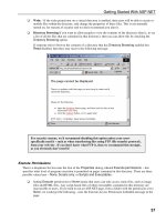
7. The left-hand side of Debug Configurations contains a tree for organizing different
collections of debug settings. You should expand the tree’s Renesas GDB Hardware
Debugging entry and then select uCOSIII_Lab_1, as shown in the screen shot on the
next page of this document. To start your session, you should click the Debug button
located at the bottom of the dialog.
4
8. After you click Debug, e2studio will display the below Confirm Perspective Switch
dialog, informing you that “this kind of launch is configured to open the Renesas Debug
perspective.” You should simply click this dialog’s Yes button.
5
9. The buttons that can be used to control debugging in e2studio are shown below. For
your debugging session, you should simply click the Resume button twice. After the
second click, the circular array of LEDs on your YRDKRX63N board should begin lighting.
This behavior can be taken as an indication that the µC/OS-III-based application code is
running successfully.
Lab 2: Writing a Task
Objectives: In this lab, you will be taken through the process of writing a task for a µC/OS-III
application. You’ll begin your work with application code that manipulates the YRDKRX63N’s
LEDs, much like what you saw in the first lab. You’ll write a new task that outputs messages to
the board’s graphical LCD, and you’ll add this task to the existing application. In the process,
you’ll gain experience with µC/OS-III’s task creation routine, OSTaskCreate(). You’ll also
have an opportunity to work with the kernel’s time-management services.
Procedure:
1. uCOSIII_Lab_2 is the project provided for this lab. You should now expand the listing for
this project in the Project Explorer. Subsequently, you should expand the src folder and
then the App folder.
2. You will be manipulating two files in this lab, app.c and app_cfg.h, both of which reside
in the App folder. You should open app_cfg.h now, by simply double-clicking its name in
the Project Explorer.
3. Two lines of code that you should now add to app_cfg.h are shown below. The first line
is a definition for a task priority. app_cfg.h, already defines one such priority,
APP_TASK_START_PRIO, and you can place the new definition directly below this
one. The second line of code defines a stack size, and this line can likewise be placed
below app_cfg.h’s existing stack-size definition, APP_TASK_START_STK_SIZE.
#define APP_TASK_LCD_PRIO 6u
#define APP_TASK_LCD_STK_SIZE 512u
Resume
6
4. After adding the priority and stack-size definitions to app_cfg.h, you should save this file
by selecting Save from the File menu. You should then open app.c.
5. The first two lines of code for you to add to app.c are shown below. This code declares
a task control block (TCB) and a stack, both of which will be needed by your new task.
Within app.c, you should place the two new lines below the comment block reading
LOCAL VARIABLES.
static OS_TCB AppTaskLCDTCB;
static CPU_STK AppTaskLCDStk[APP_TASK_LCD_STK_SIZE];
6. A prototype for your new task is provided below. You should now add this prototype to
app.c, placing it beneath the FUNCTION PROTOTYPES header.
static void AppTaskLCD (void *p_arg);
7. The below function will serve as your task. You should append this function to the end
of app.c now. The code that the function contains writes messages to the YRDKRX62N
board’s LCD by calling BSP_GraphLCD_StringPos(). To control the amount of
time that each message is displayed, the code invokes the µC/OS-III delay function
OSTimeDlyHMSM(), which is, essentially, a request for the kernel to run another task
for a specified period of time.
static void AppTaskLCD (void *p_arg)
{
OS_ERR err;
while (DEF_TRUE) {
BSP_GraphLCD_Clear();
BSP_GraphLCD_StringPos(3, 5, "DevCon");
BSP_GraphLCD_StringPos(4, 6, "2012");
OSTimeDlyHMSM(0, 0, 5, 0,
OS_OPT_TIME_HMSM_STRICT, &err);
BSP_GraphLCD_Clear();
BSP_GraphLCD_StringPos(3, 4, "Micrium");
BSP_GraphLCD_StringPos(4, 3, "uC/OS-III");
OSTimeDlyHMSM(0, 0, 5, 0,
OS_OPT_TIME_HMSM_STRICT, &err);
}
}
7
8. A C function does not, of course, become a task just by being declared. Application code
must actually notify µC/OS-III that the function is to be treated as a task.
OSTaskCreate() can be used for this purpose. You should now add the below
OSTaskCreate() call to app.c. The best location for the call is in
AppTaskStart(), just above the infinite loop.
OSTaskCreate((OS_TCB *)&AppTaskLCDTCB,
(CPU_CHAR *)"LCD Task",
(OS_TASK_PTR ) AppTaskLCD,
(void *) 0,
(OS_PRIO ) APP_TASK_LCD_PRIO,
(CPU_STK *)&AppTaskLCDStk[0],
(CPU_STK_SIZE) APP_TASK_LCD_STK_SIZE / 10u,
(CPU_STK_SIZE) APP_TASK_LCD_STK_SIZE,
(OS_MSG_QTY ) 0u,
(OS_TICK ) 0u,
(void *) 0,
(OS_OPT )(OS_OPT_TASK_STK_CHK |
OS_OPT_TASK_STK_CLR),
(OS_ERR *)&err);
9. Once you’ve added your OSTaskCreate() call to app.c, you should save this file.
You should then attempt to build and run your code, following the procedu re given in
Lab 1. When you’ve completed this procedure, you can look for your board’s LEDs to
begin lighting. Additionally, you can check for messages on the board’s LCD. “DevCon”
and “2012” should appear on the display first and should be followed by “Micrium” and
“uC/OS-III” Each of pair of messages should be visible for five seconds before the
pattern begins repeating itself.
Lab 3: Interrupt Handlers
Objective: To complete this exercise, you’ll need to add both a task and an interrupt service
routine (ISR) to an existing application. The ISR will read values from the 12-bit analog-to-
digital converter that the microcontroller on the YRDKRX63N incorporates. These values will
ultimately be output to the board’s LCD by the task. As you implement this functionality, you’ll
gain insight into how ISRs can be used in multitask applications.
8
Procedure:
1. The project provided for this lab is uCOSIII_Lab_3. You should now open this project’s
copy of app_cfg.h.
2. In this lab, as in the previous one, you will be writing a task. You should now add
definitions for your task’s priority and stack size to app_cfg.h. You can use the
definitions shown below.
#define APP_TASK_LCD_PRIO 6u
#define APP_TASK_LCD_STK_SIZE 512u
3. Once you’ve completed the above additions, you should save app_cfg.h. You should
then open app.c and add the below variable declarations to this file. The declarations
are for a TCB, a stack, and a 16-bit variable that your task will use to store analog-to-
digital values. You can place the declarations below the comment block reading LOCAL
VARIABLES.
static OS_TCB AppTaskLCDTCB;
static CPU_STK AppTaskLCDStk[APP_TASK_LCD_STK_SIZE];
static CPU_INT16U AppADCVal;
4. You should prototype your task as shown below. You can place your prototype under
the FUNCTION PROTOTYPES comment block in app.c.
static void AppTaskLCD (void *p_arg);
5. The code that will make up your task is provided on the following page. Like the task
that you wrote in Lab 2, this code uses calls to BSP_GraphLCD_StringPos() to
output messages to the YRDKRX63N board’s LCD. The variable, AppADCVal, that the
code repeatedly writes to the display via these calls, will, in the finished code, be
updated by your ISR. You will write this routine in subsequent steps. For now, you
should add the below code to app.c, placing it at the end of the file.
9
static void AppTaskLCD (void *p_arg)
{
CPU_CHAR adc_str[5];
OS_ERR err;
BSP_ADCInit();
BSP_GraphLCD_StringPos(3, 1, "ADC Value:");
while (DEF_TRUE) {
Str_FmtNbr_Int32U(AppADCVal, 4, 10, ' ', DEF_NO,
DEF_YES, adc_str);
BSP_GraphLCD_StringPos(4, 4, adc_str);
OSTimeDlyHMSM(0u, 0u, 0u, 50u,
OS_OPT_TIME_HMSM_STRICT, &err);
}
}
6. The OSTaskCreate() call for your new task is provided below. You should insert this
call into app.c’s declaration of AppTaskStart(), just above the infinite loop.
OSTaskCreate((OS_TCB *)&AppTaskLCDTCB,
(CPU_CHAR *)"LCD Task",
(OS_TASK_PTR ) AppTaskLCD,
(void *) 0,
(OS_PRIO ) APP_TASK_LCD_PRIO,
(CPU_STK *)&AppTaskLCDStk[0],
(CPU_STK_SIZE) APP_TASK_LCD_STK_SIZE / 10u,
(CPU_STK_SIZE) APP_TASK_LCD_STK_SIZE,
(OS_MSG_QTY ) 0u,
(OS_TICK ) 0u,
(void *) 0,
(OS_OPT )(OS_OPT_TASK_STK_CHK |
OS_OPT_TASK_STK_CLR),
(OS_ERR *)&err);
10
7. The ISR that your finished code will use to process analog-to-digital converter interrupts
is shown below. This function reads a new value from the converter and places that
value into AppADCVal. You should add the ISR to app.c now. You can append it to the
end of the file.
void AppADCRead (void)
{
AppADCVal = S12AD.ADDR2;
}
8. Once you’ve written the ISR, you can save app.c. You should then expand the BSP
subfolder of src and open one of the files comprising this subfolder: bsp_adc_a.s, the
contents of which were written so as to be called by the code located at the analog-to-
digital converter’s interrupt vector. You should insert the below code into bsp_adc_a.s,
just below the line of assembly language that executes the macro OS_ISR_ENTER.
The new code will cause the function that you added to app.c in the previous step to be
invoked after every analog-to-digital converter interrupt.
MOV.L #_AppADCRead, R5
JSR R5
9. You should save bsp_adc_a.s after making the above change. You can then attempt to
build and run your code. If you successfully completed each of the above steps, the
code should cause your YRDKRX63N’s LEDs to light. It should also result in an analog-to-
digital-conversion value appearing on the board’s display. You should be able to change
this value by turning the potentiometer located at the bottom of the board.
Lab 4: Task Synchronization
Objective: In this lab, you’ll again be writing an ISR and a task, both of which will behave
somewhat similarly to their counterparts in the previous lab. Your ISR for this lab, however, will
not place analog-to-digital conversion values in a variable. Instead, it will signal your task using
a semaphore. The task will then read the values itself and display them. As you write the task
and the ISR, you’ll gain familiarity with µC/OS-III’s semaphore API.
11
Procedure:
1. You’ll use project uCOSIII_Lab_4 for this lab. You should now open this project’s copy of
app_cfg.h.
2. The below definitions are for your task’s priority and stack size. You should add these
definitions to app_cfg.h now.
#define APP_TASK_LCD_PRIO 6u
#define APP_TASK_LCD_STK_SIZE 512u
3. After saving app_cfg.h, you should add the below code to app.c. This code comprises
stack and TCB declarations similar to those that you’ve seen before, along with a new
declaration for a semaphore. The semaphore will be used by your task and ISR for
signaling. You can place the semaphore, TCB, and stack declarations below app.c’s
LOCAL VARIABLES comment block.
static OS_TCB AppTaskLCDTCB;
static CPU_STK AppTaskLCDStk[APP_TASK_LCD_STK_SIZE];
static OS_SEM AppSemADC;
4. The below prototype is for your task. You should add this prototype to app.c now. You
can place the prototype below the FUNCTION PROTOTYPES comment block.
static void AppTaskLCD (void *p_arg);
5. Your task’s code is provided on the next page. This code uses a call to µC/OS-III’s
OSSemPend() function to wait for a signal from the analog-to-digital converter’s ISR.
(You will be writing the ISR soon.) After receiving the signal, the code reads a new value
from the converter and displays that value, using BSP_GraphLCD_StringPos().
You should append the code to the end of app.c now.
12
static void AppTaskLCD (void *p_arg)
{
CPU_INT16U adc_val;
CPU_CHAR adc_str[5];
OS_ERR err;
BSP_ADCInit();
BSP_GraphLCD_StringPos(3, 1, "ADC Value:");
while (DEF_TRUE) {
OSSemPend(&AppSemADC, 0, OS_OPT_PEND_BLOCKING, 0,
&err);
adc_val = S12AD.ADDR2;
Str_FmtNbr_Int32U(adc_val, 4, 10, ' ', DEF_NO,
DEF_YES, adc_str);
BSP_GraphLCD_StringPos(4, 4, adc_str);
}
}
6. Like previous tasks you’ve written, the one for this lab necessitates an
OSTaskCreate() call. Additionally, the semaphore that the task uses requires an
OSSemCreate() call. Both of these function calls are provided below. You should
now add the calls to app.c, inserting them into AppTaskStart(), just above the
infinite loop.
OSSemCreate(&AppSemADC, "ADC Sem", 0, &err);
OSTaskCreate((OS_TCB *)&AppTaskLCDTCB,
(CPU_CHAR *)"LCD Task",
(OS_TASK_PTR ) AppTaskLCD,
(void *) 0,
(OS_PRIO ) APP_TASK_LCD_PRIO,
(CPU_STK *)&AppTaskLCDStk[0],
(CPU_STK_SIZE) APP_TASK_LCD_STK_SIZE / 10u,
(CPU_STK_SIZE) APP_TASK_LCD_STK_SIZE,
(OS_MSG_QTY ) 0u,
(OS_TICK ) 0u,
(void *) 0,
(OS_OPT )(OS_OPT_TASK_STK_CHK |
OS_OPT_TASK_STK_CLR),
(OS_ERR *)&err);
13
7. The below code will serve as your ISR. Unlike the ISR from the previous lab, this one
does not read a value from the analog-to-digital converter. Instead, it calls the µC/OS-III
function OSSemPost() to notify your task that a new value is available. You should
now add the ISR to app.c. You can place it just below your task.
void AppADCRead (void)
{
OS_ERR err;
OSSemPost(&AppSemADC, OS_OPT_POST_1, &err);
}
8. You can attempt to build and run your code after saving the changes to app.c. The code
should exhibit the same behavior that you observed in Lab 3: Your board’s LEDs should
light, and the most recent value form the analog-to-digital converter should appear on
the LCD.