Sensorless Vector Control with RL78G14 (1)
Bạn đang xem bản rút gọn của tài liệu. Xem và tải ngay bản đầy đủ của tài liệu tại đây (1.65 MB, 29 trang )
Renesas Electronics America Inc.
© 2012 Renesas Electronics America Inc. All rights reserved.
Sensorless Vector Control with RL78G14
© 2012 Renesas Electronics America Inc. All rights reserved.2
Renesas Technology & Solution Portfolio
© 2012 Renesas Electronics America Inc. All rights reserved.3
Microcontroller and Microprocessor Line-up
Wide Format LCDs
Industrial & Automotive, 130nm
350µA/MHz, 1µA standby
44 DMIPS, True Low Power
Embedded Security, ASSP
165 DMIPS, FPU, DSC
1200 DMIPS, Performance
1200 DMIPS, Superscalar
500 DMIPS, Low Power
165 DMIPS, FPU, DSC
25 DMIPS, Low Power
10 DMIPS, Capacitive Touch
Industrial & Automotive, 150nm
190µA/MHz, 0.3µA standby
Industrial, 90nm
242µA/MHz, 0.2µA standby
Automotive & Industrial, 90nm
600µA/MHz, 1.5µA standby
Automotive & Industrial, 65nm
600µA/MHz, 1.5µA standby
Automotive, 40nm
500µA/MHz, 35µA deep standby
Industrial, 40nm
242µA/MHz, 0.2µA standby
Industrial, 90nm
1mA/MHz, 100µA standby
Industrial & Automotive, 130nm
144µA/MHz, 0.2µA standby
2010
2013
32-bit8/16-bit
© 2012 Renesas Electronics America Inc. All rights reserved.4
Enabling the Smart Society
Industrial
Motors
Smart
Metering
Energy
harvesting
Home
Automation
Energy efficiency is key to a Smart Society
Motor control is key to efficient energy management
© 2012 Renesas Electronics America Inc. All rights reserved.5
Agenda
Introduction to the Field Oriented Control (FOC) with
Sensorless Speed and Position Detection
Challenges to implement SVC on 16-bit MCUs
RL78G14 special features
Implementation with RL78G14
Introduction to the RL78G14 kit
Lab procedure
Setup Sensorless Vector Control Demo
Sample motor currents and DC bus voltage
Drive motor in open loop
Understand sensorless position and speed estimation
Drive motor by closing the speed loop
Tune motor operation
© 2012 Renesas Electronics America Inc. All rights reserved.6
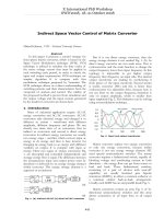
Sensorless Vector Control Loop
θ
*
r
ω
Speed Regulator
r
ω
∆
*
q
i
0
*
=
d
i
r
ω
id PI
Regulator
iq PI
Regulator
d,q
to
βα
,
)(
1
θ
−
T
Motor Model
Based Flux and
Position Observer
q
i
d
i
*
q
U
*
d
U
*
α
U
*
β
U
Voltage
Source
3-phase
Inverter
SIN
PWM
PWM1~6
to
a, b, c
βα
,
3-phase
PMSM
r
ω
to
d,q
βα
,
)(
θ
T
a
i
b
i
d
i
q
i
α
i
β
i
a,b,c
to
βα
,
Speed Estimation
θ
DC Bus
Commanded
speed
Actual
speed
Clarke transformPark transform
Inverse
Clarke transform
Inverse
Park transform
Computation intensive operations
© 2012 Renesas Electronics America Inc. All rights reserved.7
Examples of control equations
Phase voltages: νa, νb, νc
– ia, ib, ic phase currents
– Rs stator resistance
– λ magnetic flux linkage
Clark transformation
– 3-phase to 2-phase in stator frame
Park transformation
– ω angular speed
– L mutual inductance
© 2012 Renesas Electronics America Inc. All rights reserved.8
Challenges of 16-bit MCUs for Motor Control
Most 16-bit MCUs are CISC architecture
Good code density (smaller memory needed)
Execution time may not be fast enough for real-time control
Representation of quantities is range limited
0 to 65536 unsigned
-32768 to 32768 signed
Without FPU scaling needs to be used
Scaling limitation
Multiply-Accumulate (MAC) operation: a = a + (b * c)
d = b * c
a = a + d
Can the 16-Bit MCUs do field oriented sensorless control?
Yes with the right performance and peripherals!
© 2012 Renesas Electronics America Inc. All rights reserved.9
RL78G14: 16-bit MCU for Motor Control
Communications
2 x I
2
C
Master / Slave
1 x I
2
C
Multi-Master
2 x CSI/SPI
7-, 8-bit
3 x UART
7-, 8-, 9-bit
1 x LIN
1ch
Analog
ADC
10-bit, 12ch
Internal Vref.
Memory
Program Flash
up to 64KB
SRAM
up to 5.5KB
Data Flash
up to 4KB
System
Interrupt Controller
4 Levels, 20 pins
Power Management
HALT
RTC,DMA Enabled
SNOOZE
Serial,ADC Enabled
STOP
SRAM On
Timers
2 x Timer Array
16-bit, 4ch
Interval Timer
12-bit, 1ch
Window WDT
17-bit , 1ch
RTC
Calendar
Temp. Sensor
Safety
RAM
Parity Check/protection
POR, LVD
MUL/DIV/MAC
Debug
Single-Wire
ADC
Self-diagnostic
SFR
protection
Memory
CRC
Clock system
External Clock
20MHz
External Clock
32.768KHz
Internal OCO
up to 64MHz
Internal LOCO
15KHz
Clock
Monitoring
DTC
Motor Control Support
16-Bit Motor Control Timers
– 64MHz / 1% Internal Clock
– RD for 3-Phase PWM
– RJ for interrupt culling
– RG for quadrature encoder
ADC trigger
Event Link Controller (ELC)
Data Transfer Controller (DTC)
Hardware Safety
– Independent Watchdog
– Hardware shutdown
Self-test
o Flash ECC, RAM Parity, H/W CRC,
WDT, A/D, RAM/SFR write protect,
Clock monitor
Motor Control
3ph MC Timer RD
16-bit with dead time
Encoder Timer RG
16-bit, 1ch
Timer RJ
16-bit , 1ch
ELC
16-Bit CISC CPU Core
41 DMIPS @32MHz
3-stage pipelined Harvard architecture
MUL/DIV/MAC instructions
16-Bit Barrel Shifter
© 2012 Renesas Electronics America Inc. All rights reserved.10
High Performance Optimized Architecture
16-bit CPU core with pipelining
Efficient instruction execution – 86% in 1-2 cycles
Single cycle multiplication (HW math assist)
Data transfer controller (up to 24 channels)
HW math assist Operation
Clock
cycles
16-bit barrel shifter shift/rotate by n (n = 1-15) 1
multiply signed & unsigned 16 x 16 = 32 Bit result 2
multiply/accumulate signed & unsigned 16 x 16 + 32 = 32 Bit result 3
© 2012 Renesas Electronics America Inc. All rights reserved.11
Motor Timer RD
TRDGRA0
TRDGRB0
TRDGRA1
TRDGRB1
TRDGRD0
TRDGRC1
TRDGRD1
DUTY 1
DUTY 2
DUTY 3
PERIOD
Waveform
Control
Timer RD Registers
RD0
RD1
Buffer Compare
U
/U
V
/V
W
/W
TRDIOC0
TRDIOB0
TRDIOD0
TRDIOA1
TRDIOC1
TRDIOB1
TRDIOD1
© 2012 Renesas Electronics America Inc. All rights reserved.12
Complementary PWM Operation
Value in TRDGRA0
Value in TRDGRB0
Value in TRDGRA1
Value in TRDGRB1
TRDIOB0 Output
TRDIOD0 Output
TRDIOA1 Output
TRDIOC1 Output
TRDIOB1 Output
TRDIOD1 Output
U
/U
V
/V
W
/W
TRD0
TRD1
© 2012 Renesas Electronics America Inc. All rights reserved.13
Event Link Controller (ELC)
Standard processing Processing with ELC
CPU
Comparator
Timer
A/D
Interrupt
Controller
External
analog input
voltage
CPU
Comparator
Timer
A/D
Interrupt
Controller
ELC
External
analog input
voltage
ELC links Inputs and Outputs of internal peripherals
Performance benefits:
Reduces CPU load, interrupts, program size and power consumption
Improves real-time operation
Enables direct control of I/O ports and built in event timers
Using Interrupt: > 9-16 cyc
ELC: 3cyc
© 2012 Renesas Electronics America Inc. All rights reserved.14
Data Transfer Controller (DTC)
Data transfer between memory and registers without CPU use
Reduced CPU overhead
CPU
DTC DTC
DTC unused DTC used
DTC Performance (G14 64-pin)
Number of channels 24 ch
Address space for transfer 64 KB
Max. transmission time/ Block size 256 times / 512B
Transmission target
memory ⇔ memory
memory ⇔ SFR
Activation sources 31
Memory,
SFR
CPU
Memory,
SFR
© 2012 Renesas Electronics America Inc. All rights reserved.15
Control loop cycle management
PWM interrupt culling (skipping)
– Timer RD: PWM frequency - 24KHz
– Timer RJ: Event count mode
Count down from 2 to 0
– ELC : Input from Timer RD
Output to Timer RJ
– Control loop frequency set by Timer RJ underflow
interrupt @8KHz
RL78/G14 Use for Motor Control
CPU
Timer RD
Timer RJ
Interrupt
Controller
ELC
Timer RD
Event Link
Controller
TRD1
Underflow
Trigger
Event
Input
Trigger
Complementary
PWM
Timer RJ
Event
Counter
© 2012 Renesas Electronics America Inc. All rights reserved.16
Software Flow – Main Loop
Hardware and software Init
Interrupt enabling
125us Interrupt
10ms Main loop
Main loop
synchronization
Main loop body
Speed ramp management
Communication management
General board management
Parameter modification management
cnt_init==0?
cnt_init=NUM_INT
© 2012 Renesas Electronics America Inc. All rights reserved.17
Software Flow – Control Interrupt
Phase current reading
Park and Clarke transformations
iu, iv, iw iα, iβ id, iq
DC bus voltage reading
Rotor phase angle calculation
Current PI processing
(idref, iqref), (idmea, iqmea), vdout, vqout
Inverse Clarke and Park transformations
vdout, vqout vαout, vβout, vuout, vvout, vwout
PWM duty update
Rotor phase estimation:
θest
Speed estimation: ωest
Speed PI processing or Start up
Main loop synchronization
© 2012 Renesas Electronics America Inc. All rights reserved.18
Physical quantities represented as 16-bit signed integers
sin(), cos(): (-1 to +1) x 16384 -16384 to +16384
Voltages (V): (0 to 511.9) x 64 32768
Currents (A): (0 to 32) x 1024 32768
Resistance (Ω): (0 to 128) x 256 32768
Inductance (Henry): (0 to 2) x 16384 32768
Magnetic flux (Weber): (0 to 8) x 4096 32768
32-Bit: -2147483648 to +2147483648
16-Bit: -32768 to +32768
© 2012 Renesas Electronics America Inc. All rights reserved.19
High Integration = Cost Reduction
Supply
Voltage Monitoring
Voltage Regulator
(1.6V to 5.5V input)
Dedicated flash memory for data
storage (Data Flash)
Accurate Internal
Oscillators
Temperature
Sensor
REG
Temp.
Sensor
DATA
FLASH
OCO
RL78
CPU
LVD
POR
CODE
FLASH
SRAM
PERIPHERALS
PERIPHERALS
Reset IC
X1
Regulator
IC
Internal Reset
EEPROM
IC
Temp.
IC
WDT
20mA port drive
(no need for external
transistors)
IEC60730 in HW
(Easier/quicker
certification)
Reduce system BOM by eliminating external components
© 2012 Renesas Electronics America Inc. All rights reserved.20
Sensorless Vector Control Lab Agenda
Setup Sensorless Vector Control Demo
Sample motor currents and DC bus voltage
Drive motor in open loop
Understand sensorless position and speed estimation
Drive motor by closing the speed loop
Tune motor operation
© 2012 Renesas Electronics America Inc. All rights reserved.21
Introduction to the RL78G14 Kit
© 2012 Renesas Electronics America Inc. All rights reserved.22
RL78G14 Kit
© 2012 Renesas Electronics America Inc. All rights reserved.23
RL78G14 Board
© 2012 Renesas Electronics America Inc. All rights reserved.24
Skill Level
1. Familiar with motor control
techniques
2. Familiar with sensorless
vector control concepts
3. Familiar with IAR Embedded
Workbench
Time to Complete Lab
100 Minutes
Lab Materials
Please verify you have the
following materials at your lab
station.
RL78G14 Motor Control
Evaluation Kit with E1
emulator, two USB cables,
24V DC power supply,
control board and motor
Laptop with the CD drive
Lab Objectives
1. Get familiar with the RL78G14
starter kit and drive the motor.
2. Understand ADC sampling to
measure motor currents and DC
bus voltage.
3. Drive the motor in open loop.
4. Understand sensorless position and
speed estimation.
5. Drive motor by closing the speed
loop
6. Understand motor tuning
Lab Overview
© 2012 Renesas Electronics America Inc. All rights reserved.25
Enabling the Smart Society
Industrial
Motors
Smart
Metering
Energy
harvesting
Home
Automation
Energy efficiency is key to a Smart Society
Motor control is key to efficient energy management