HỆ THỐNG NHIÊN LIỆU ĐỘNG CƠ 1NZFE TOYOTA
Bạn đang xem bản rút gọn của tài liệu. Xem và tải ngay bản đầy đủ của tài liệu tại đây (3.33 MB, 47 trang )
1NZ-FE FUEL – FUEL SYSTEM
FU–1
FU
FUEL SYSTEM
PRECAUTION
1. PRECAUTIONS
(a) Before working on the fuel system, disconnect the
cable from the negative battery terminal.
(b) Do not work on the fuel system near any naked
flames. Never smoke during the work.
(c) Keep rubber and leather parts away from gasoline.
2. DISCHARGE FUEL SYSTEM PRESSURE
CAUTION:
• Before removing any fuel system parts, take
precautions to prevent gasoline spillage.
• As some pressure remains in the fuel line even
after taking precautions to prevent gasoline
spillage, use a shop rag or piece of cloth to
prevent gasoline splashes when disconnecting
the fuel line.
(a) Remove the rear seat cushion (for Hatchback) (See
page SE-114).
(b) Remove the rear seat assembly (for Hatchback)
(See page SE-70).
(c) Remove the rear seat cushion (for Sedan) (See
page SE-46).
(d) Remove the rear floor service hole cover.
(e) Disconnect the connector from the fuel pump
assembly.
(f) Start the engine. After the engine stops naturally,
turn the ignition switch OFF.
HINT:
DTC P0171 may be set.
(g) Crank the engine again and make sure that the
engine does not start.
(h) Remove the fuel tank cap and discharge the
pressure.
(i) Disconnect the cable from the negative battery
terminal.
(j) Connect the connector of the fuel pump assembly.
3. FUEL SYSTEM
(a) When disconnecting the high-pressure fuel line, a
large amount of gasoline will splash. So take the
following precautions.
(1) Discharge the fuel system pressure.
(2) Disconnect the fuel tube.
A115462
FU–2
1NZ-FE FUEL – FUEL SYSTEM
FU
(3) Drain the fuel remaining inside the fuel pump
tube.
(4) Cover the disconnected fuel tube connector and
pipe with a vinyl bag to prevent damage and the
intrusion of foreign matter.
(b) Observe the following precautions when removing
and installing the fuel injector.
(1) Do not reuse the O-ring.
(2) When placing a new O-ring onto the injector, do
not damage the O-ring.
(3) Coat the new O-ring with grease or gasoline
before installing it. Do not use engine, gear or
brake oil.
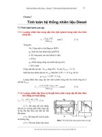
(c) Install the injector into the delivery pipe and cylinder
head, as shown in the illustration. Apply grease or
gasoline oil to the contact surfaces of the delivery
pipe and injector before installing the injector.
(d) Observe these precautions when disconnecting the
fuel tube connector.
(1) Remove the fuel pipe clamp No.1.
(2) Check whether there is any dirt in the pipe
around the connector before disconnecting it
and remove the dirt as necessary.
(3) If the connector and pipe are stuck, pinch the
retainer with your hand, then push and pull the
connector to disconnect them. Do not use any
tools.
(4) Check the sealing surface of the pipe for dirt and
mud. If dirty, wipe it with a shop rag or piece of
cloth.
B000679E04
A106964
Insulator
Delivery Pipe
O-ring
A090674E02
A125132
Pull
A125133E01
1NZ-FE FUEL – FUEL SYSTEM
FU–3
FU
(5) Cover the disconnected fuel tube connector and
pipe with a vinyl bag to prevent damage and the
intrusion of foreign matter.
(e) Observe the following precautions when connecting
the fuel tube connector.
(1) Check that there is no damage or foreign matter
on the part of the pipe that comes into contact
with the connector.
(2) Align the axis of the connector with the axis of
the pipe. Push the pipe into the connector until
the connector makes a click sound. If the
connection is too tight, apply a small amount of
fresh engine oil to the tip of the pipe.
(3) After connecting the pipe and connector, try to
pull them apart to confirm that they are securely
connected.
(4) Attach the lock claws to the connector by
pushing down on the cover.
4. CHECK FOR FUEL LEAKAGE
(a) Check that there is no fuel leakage after performing
maintenance anywhere on the fuel system (See
pageFU-7).
Plastic Bag
A099427E08
Push
A125134E01
Pull
A125201E01
FU–4
1NZ-FE FUEL – FUEL SYSTEM
FU
PARTS LOCATION
FUEL INJECTOR
FUEL SUCTION WITH PUMP
AND GAUGE TUBE ASSEMBLY
for Hatchback:
A119137E02
1NZ-FE FUEL – FUEL SYSTEM
FU–5
FU
FUEL INJECTOR
FUEL SUCTION WITH PUMP AND
GAUGE TUBE ASSEMBLY
for Sedan:
A133330E01
FU–6
1NZ-FE FUEL – FUEL SYSTEM
FU
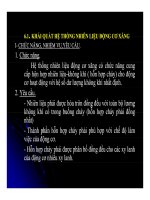
SYSTEM DIAGRAM
Pump
7.5A IGN
C/OPN
Ignition Switch
IG2
15A AM2
20A EFI
Battery
Fuel Injector 4
Fuel Injector 3
Fuel Injector 2
Fuel Injector 1
ECM
FC
IGSW
#40
#30
#20
#10
MREL
+B2
BATT
EFI
A119140E01
1NZ-FE FUEL – FUEL SYSTEM
FU–7
FU
ON-VEHICLE INSPECTION
1. CHECK FUEL PUMP OPERATION AND FUEL
LEAKAGE
(a) When using the intelligent tester.
(1) Connect the intelligent tester to the DLC3.
(2) Turn the ignition switch on (IG) and the
intelligent tester main switch on.
NOTICE:
Do not start the engine.
(3) Select the Active Test mode on the intelligent
tester.
HINT:
Refer to the intelligent tester operator's manual
for further details.
(b) Check that there is no fuel leakage anywhere on the
fuel system after doing maintenance.
2. CHECK FUEL PRESSURE
(a) Discharge the fuel system pressure (See page FU-
1).
(b) Using a voltmeter, measure the battery voltage.
Standard voltage:
11 to 14 V
(c) Disconnect the negative (-) battery terminal cable.
(d) Remove fuel pipe clamp No. 1 from the fuel tube
connector.
(e) Disconnect the fuel hose from the fuel main tube.
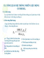
(f) Install SST (pressure gauge and fuel tube
connector) as shown in the illustration.
SST 09268-45014 (09268-41200, 09268-41220,
09268-41250), 09268-41047 (90467-13001,
95336-08070, 09268-41500)
(g) Wipe off any spilt gasoline.
(h) Reconnect the negative (-) battery terminal cable.
(i) Connect the intelligent tester to the DLC3 (see step
1 in check fuel pump operation).
(j) Measure the fuel pressure.
Fuel pressure:
304 to 343 kPa (3.1 to 3.5 kgf*cm
2
, 44.1 to 49.7
psi)
If the pressure is high, replace the fuel pressure
regulator.
If the pressure is low, check the fuel hoses, fuel
hose connections, fuel pump and fuel pressure
regulator.
(k) Disconnect the intelligent tester from the DLC3.
(l) Start the engine.
(m) Measure the fuel pressure while the engine is idling.
Fuel pressure:
304 to 343 kPa (3.1 to 3.5 kgf*cm
2
, 44.1 to 49.7
psi)
If the pressure is not as specified, check the
vacuum sensing hose and the fuel pressure
regulator.
SST (Pressure
Gauge)
SST (Clip)
SST (T-joint)
SST (Tube)
SST
(Hose)
SST (Tube Connector)
A105669E04
FU–8
1NZ-FE FUEL – FUEL SYSTEM
FU
(n) Stop the engine.
(o) Check that the fuel pressure remains as specified
for 5 minutes after the engine stops.
Fuel pressure:
147 kPa (1.5 kgf*cm
2
, 21 psi) or more
If the pressure is not as specified, check the fuel
pump, pressure regulator and injectors.
(p) After checking the fuel pressure, disconnect the
negative (-) battery terminal cable and carefully
remove SST to prevent gasoline splashes.
(q) Reconnect the fuel tube to the fuel main tube.
(r) Install fuel pipe clamp No. 1 onto the fuel tube
connector.
(s) Check for fuel leakage (step 1).
1NZ-FE FUEL – FUEL INJECTOR
FU–9
FU
ENGINE1NZ-FE FUEL
FUEL INJECTOR
COMPONENTS
N*m (kgf*cm, ft.*lbf)
: Specified torque
7.0 (71, 62 in.*lbf)
7.0 (71, 62 in.*lbf)
CYLINDER HEAD COVER NO. 2
A115136E01
FU–10
1NZ-FE FUEL – FUEL INJECTOR
FU
N*m (kgf*cm, ft.*lbf)
: Specified torque
9.0 (92, 80 in.*lbf)
IGNITION COIL NO. 1
A115486E01
1NZ-FE FUEL – FUEL INJECTOR
FU–11
FU
VENTILATION HOSE
WIRE HARNESS BRACKET
SEAL WASHER
N*m (kgf*cm, ft.*lbf)
: Specified torque
10 (102, 7.0)
13 (133, 9.6)
x7
CYLINDER HEAD COVER
SUB-ASSEMBLY
CYLINDER HEAD COVER GASKET
VENTILATION HOSE NO. 2
10 (102, 7.0)
10 (102, 7.0)
10 (102, 7.0)
A115504E01
FU–12
1NZ-FE FUEL – FUEL INJECTOR
FU
FUEL DELIVERY PIPE
SUB-ASSEMBLY
FUEL INJECTOR ASSEMBLY
FUEL TUBE SUB-ASSEMBLY
FUEL PIPE CLAMP
19 (194, 14)
9.0 (92, 80 in.*lbf)
N*m (kgf*cm, ft.*lbf) : Specified torque
x2
x2
x4
Non-reusable part
INJECTOR VIBRATION INSULATOR
O-RING
DELIVERY PIPE
NO. 1 SPACER
A115505E01
1NZ-FE FUEL – FUEL INJECTOR
FU–13
FU
REMOVAL
1. DISCHARGE FUEL SYSTEM PRESSURE
(See page FU-1)
2. DISCONNECT CABLE FROM NEGATIVE BATTERY
TERMINAL
3. REMOVE CYLINDER HEAD COVER NO. 2 (See page
IG-9)
4. REMOVE IGNITION COIL NO. 1 (See page IG-9)
5. REMOVE VENTILATION HOSE
(a) Disconnect the ventilation hose.
6. REMOVE VENTILATION HOSE NO. 2
(a) Disconnect ventilation hose No. 2.
7. REMOVE CYLINDER HEAD COVER SUB-ASSEMBLY
(a) Disconnect the fuel injector connectors.
A115487
A115488
A115489
FU–14
1NZ-FE FUEL – FUEL INJECTOR
FU
(b) Disconnect the connector and 3 wire harness
clamps shown in the illustration and disconnect the
engine wire harness.
(c) Remove the bolt and remove the wire harness
bracket.
(d) Remove the 9 bolts, 2 nuts and 2 seal washers and
then remove the cylinder head cover sub-assembly.
8. DISCONNECT FUEL TUBE SUB-ASSEMBLY
(a) Remove the fuel pipe clamp.
A115490
A115491
A066472E01
A115492
1NZ-FE FUEL – FUEL INJECTOR
FU–15
FU
(b) Pinch the retainer of the fuel tube connector, then
pull the fuel tube connector to disconnect the fuel
tube out of the fuel delivery pipe sub-assembly.
NOTICE:
• Remove any dirt and foreign matter from the
fuel tube connector before performing this
work.
• Do not allow any scratches or foreign matter
on the parts when disconnecting, as the fuel
tube connector has the O-ring that seals the
pipe.
• Perform this work by hand. Do not use any
tools.
• Do not forcibly bend, twist or turn the nylon
tube.
• Protect the disconnected parts by covering
them with a vinyl bag after disconnecting the
fuel tube.
• If the fuel tube connector and pipe are stuck,
push and pull to release them.
9. REMOVE FUEL DELIVERY PIPE SUB-ASSEMBLY
(a) Remove the 3 bolts and remove the fuel delivery
pipe sub-assembly with 4 fuel injectors.
NOTICE:
Do not drop the fuel injectors when removing
the fuel delivery pipe sub-assembly.
10. REMOVE DELIVERY PIPE NO. 1 SPACER
(a) Remove the 2 delivery pipe No. 1 spacers.
11. REMOVE INJECTOR VIBRATION INSULATOR
(a) Remove the 4 injector vibration insulators.
Pinch
Retainer
Nylon Tube
O-Ring Pipe
A117474E01
A115494
A115496
A115497
FU–16
1NZ-FE FUEL – FUEL INJECTOR
FU
12. REMOVE FUEL INJECTOR ASSEMBLY
(a) Pull the 4 fuel injector assemblies out of the fuel
delivery pipe sub-assembly.
INSPECTION
1. INSPECT FUEL INJECTOR ASSEMBLY
(a) Check the resistance.
(1) Using an ohmmeter, measure the resistance
between the terminals.
Standard resistance:
11.6 to 12.4 Ω at 20°C (68°F)
If the result is not as specified, replace the
injector assembly.
(b) Check the operation.
CAUTION:
Perform the inspection in a well-ventilated area.
Do not perform the inspection near any naked
flames.
(1) Connect SST (fuel tube connector) to SST
(hose), then connect them to the fuel pipe
(vehicle side).
SST 09268-41048 (90467-13001, 95336-
08070, 09268-41500)
(2) Install the O-ring onto the fuel injector
assembly.
(3) Connect SST (adaptor and hose) to the injector
assembly, and hold the injector assembly and
union with SST (clamp).
SST 09268-41048 (09268-41110, 90467-
13001, 95336-08070, 09268-41310)
(4) Set the injector assembly in a graduated
cylinder.
CAUTION:
Install a suitable vinyl tube onto the injector
assembly to prevent gasoline splashes.
(5) Operate the fuel pump (see page FU-7 ).
Pull
A115498E01
Ohmmeter
A116182E01
SST (Clip)
SST (Hose)
Fuel Pipe
SST (Fuel Tube Connector)
A088382E01
SST (Hose)
SST (Adaptor)
Vinyl Tube
SST (Clip)
SST (Clamp)
A116183E01
1NZ-FE FUEL – FUEL INJECTOR
FU–17
FU
(6) Connect SST (wire) to the injector assembly
and the battery for 15 seconds, and measure
the injection volume with the graduated
cylinder. Test each injector 2 or 3 times.
SST 09842-30080
Injection volume:
47 to 58 cm
3
(2.9 to 3.5 cu in.) per 15
seconds
Difference between each injector:
11 cm
3
(0.6 cu in.) or less
NOTICE:
Always do the switching at the battery side.
If the injection volume is not as specified,
replace the injector assembly.
(c) Check the leakage.
(1) In the condition above, disconnect the test
probes of SST (wire) from the battery and
check the injector for fuel leakage.
Fuel drop:
1 drop or less every 12 minutes
INSTALLATION
1. INSTALL FUEL INJECTOR ASSEMBLY
(a) Apply a light coat of gasoline or spindle oil to new O-
rings, then install one onto each fuel injector.
(b) Apply a light coat of gasoline or spindle oil to the
contact surfaces of the fuel delivery pipe and the O-
ring of the fuel injector.
(c) While turning the fuel injector left and right, install it
onto the fuel delivery pipe.
NOTICE:
• Do not twist the O-ring.
• After installing the fuel injectors, check that
they turn smoothly. If not, replace the O-ring
with a new one.
Connect
SST
(Wire)
A075915E04
A116184
O-Ring
A115499E01
Turn
Push
A115500E01
FU–18
1NZ-FE FUEL – FUEL INJECTOR
FU
2. INSTALL INJECTOR VIBRATION INSULATOR
(a) Install 4 new injector vibration insulators onto the
cylinder head.
3. INSTALL DELIVERY PIPE NO. 1 SPACER
(a) Install the 2 No. 1 delivery pipe spacers onto the
cylinder head.
NOTICE:
Install the delivery pipe No. 1 spacer in the
correct direction.
4. INSTALL FUEL DELIVERY PIPE SUB-ASSEMBLY
(a) Install the fuel delivery pipe sub-assembly with the 4
fuel injectors, then provisionally install the 3 bolts.
NOTICE:
• Do not drop the fuel injectors when installing
the fuel delivery pipe sub-assembly.
• Check that the fuel injectors rotate smoothly
after installing the fuel delivery pipe sub-
assembly.
(b) Tighten the 3 bolts to the specified torque.
Torque: 19 N*m (194 kgf*cm, 14 ft.*lbf) for bolt A
9.0 N*m (92 kgf*cm, 80 in.*lbf) for bolt B
5. CONNECT FUEL TUBE SUB-ASSEMBLY
(a) Insert the fuel tube connector into the fuel delivery
pipe until a click sound can be heard.
NOTICE:
• Check that there are no scratches or foreign
matter around the disconnected parts of the
fuel tube connector and pipe before
performing this work.
• After connecting the fuel tube, check that the
fuel tube connector and pipe are securely
connected by pulling them.
A115497
A115501
A115494
A
A
B
A115494E01
Push
A115502E01
1NZ-FE FUEL – FUEL INJECTOR
FU–19
FU
(b) Install the fuel pipe clamp.
6. INSTALL CYLINDER HEAD COVER SUB-ASSEMBLY
(a) Apply seal packing to the cylinder head as shown in
the illustration.
Seal Packing:
Toyota Genuine Seal Packing Black, Three
Bond 1207B or Equivalent
NOTICE:
• Remove any oil from the contact surface.
• Install the cylinder head cover sub-assembly
within 3 minutes of applying the seal packing.
• Do not start the engine for at least 2 hours
after the installation.
(b) Install the cylinder head cover sub-assembly with
the 9 bolts, 2 nuts and 2 seal washers.
(c) Tighten the 9 bolts and 2 nuts in the sequence
shown in the illustration.
Torque: 10 N*m (102 kgf*cm, 7.0 ft.*lbf)
(d) Install the wire harness bracket with the bolt.
Torque: 13 N*m (133 kgf*cm, 9.6 ft.*lbf)
A115492
Seal Packing
A115503E01
11
10
9
3
1
2
6
4
8
5
7
A035756E01
A115491
FU–20
1NZ-FE FUEL – FUEL INJECTOR
FU
(e) Connect the connector and wire harness clamp
shown in the illustration and connect the engine wire
harness.
(f) Connect the fuel injector connectors.
7. CONNECT VENTILATION HOSE NO. 2
(a) Connect ventilation hose No. 2.
8. CONNECT VENTILATION HOSE
(a) Connect the ventilation hose.
9. INSTALL IGNITION COIL NO. 1 (See page IG-9)
10. CONNECT CABLE TO NEGATIVE BATTERY
TERMINAL
Torque: 5.4 N*m (55 kgf*cm, 48 in.*lbf)
11. CHECK FOR FUEL LEAKAGE (See page FU-7)
12. CHECK FOR ENGINE OIL LEAKAGE
13. INSTALL CYLINDER HEAD COVER NO. 2 (See page
IG-10)
A115490
A115489
A115488
A115487
1NZ-FE FUEL – FUEL PUMP
FU–21
FU
ENGINE1NZ-FE FUEL
FUEL PUMP
COMPONENTS
for Hatchback:
REAR SEAT CUSHION COVER PAD
A119203E03
FU–22
1NZ-FE FUEL – FUEL PUMP
FU
for Sedan:
REAR SEAT CUSHION COVER PAD
A133348E01
1NZ-FE FUEL – FUEL PUMP
FU–23
FU
DECK BOARD
SUB-ASSEMBLY
DECK FLOOR BOX
REAR SEAT ASSEMBLY
REAR SEAT LEG
COVER NO. 1
REAR SEAT LEG
COVER NO. 2
x7
N*m (kgf*cm, ft*lbf) : Specified torque
37 (375, 27)
for Hatchback:
PACKAGE TRAY TRIM
PANEL ASSEMBLY
B114737E04
FU–24
1NZ-FE FUEL – FUEL PUMP
FU
FUEL PUMP GAUGE RETAINER
FUEL TANK MAIN TUBE SUB-ASSEMBLY
FUEL TANK VENT HOSE SUB-ASSEMBLY
REAR FLOOR SERVICE HOLE COVER
FUEL SUCTION TUBE GASKET
Non-reusable part
FUEL SUCTION WITH PUMP AND
GAUGE TUBE ASSEMBLY
A115458E01
1NZ-FE FUEL – FUEL PUMP
FU–25
FU
FUEL PUMP
FUEL PUMP FILTER
O-ring
FUEL FILTER
FUEL PUMP HARNESS
FUEL SENDER
GAUGE ASSEMBLY
Non-reusable part
SUCTION SUPPORT
FUEL SUCTION WITH PUMP AND GAUGE TUBE ASSEMBLY
A115459E01