Proceedings VCM 2012_05 Điều khiển thích nghi bền vững hệ truyền động qua một cặp bánh răng Robust and Adaptive Tracking Control of Two-Wheel-Gearing Transmission Systems
Bạn đang xem bản rút gọn của tài liệu. Xem và tải ngay bản đầy đủ của tài liệu tại đây (334.23 KB, 7 trang )
Tuyển tập công trình Hội nghị Cơ điện tử toàn quốc lần thứ 6 25
Mã bài: 07
Robust and Adaptive Tracking Control of Two-Wheel-Gearing
Transmission Systems
Điều khiển thích nghi bền vững hệ truyền động qua
một cặp bánh răng
Le Thi Thu Ha
1)
, Nguyen Thi Chinh
2)
, Nguyen Doan Phuoc
3)
1)
,
2)
Thai Nguyen University of Technology;
3)
Hanoi University of Science and Technology
e-mail:
1)
,
2)
,
3)
Abstract
This paper proposes a new design procedure of an adaptive and robust tracking controller for gearing
mechanical transmission systems by using the sliding mode control technique and the certainty equivalence
principle. The asymptotic tracking behavior of the system in the presence of all uncertainties caused by
backlash, friction or cogwheel elasticity is proved. The simulation results are provided to illustrate the
satisfactory performance of the closed loop system.
Keywords: Adaptive control; sliding mode; nonlinear system; backlash; cogwheel elasticity; friction
Tóm tắt
Bài báo trình bày phương pháp thiết kế bộ điều khiển bám thích nghi bền vững cho hệ truyền động qua
bánh răng trên cơ sở sử dụng nguyên tắc điều khiển trượt và thích nghi giả định rõ. Chất lượng bám ổn định
tiệm cận luôn được đảm bảo và không phụ thuộc vào sự xuất hiện của các thành phần bất định trong hệ thống
gồm khe hở, ma sát và độ không cứng vững của các bánh răng. Kết quả mô phỏng đã chứng minh khả năng
bám thích nghi bền vững rất tốt của hệ kín.
Từ khóa: Điều khiển thích nghi; điều khiển trượt; hệ phi tuyến; khe hở; bánh răng; ma sát
1. Introduction
The uncertainties that usually limit the
performance of a gearing transmission control
system in many practical applications are mainly
caused by immeasurable friction, unpredictable
elasticity of shafts and imprecise description of
backlash between cogwheels[1], [3], [7], [9].
Those inevitable uncertainties can reduce the
lifetime of the whole system or even disturb the
system behavior. Therefore, damping the torsional
vibration due to the shaft or cogwheel elasticity
and suppressing the effect of friction or backlash
are the most important control problems of
mechanical systems in general and of gearing
transmission systems in particular.
Conventionally, self-tuning PI controllers are
often used to approach these problems [8].
However, only using such PI controllers cannot
damp torsional vibrations effectively [1].
Furthermore, desired results in suppression of the
effect of the shaft elasticity or backlash between
cogwheels at once at damping torsional vibrations
cannot be achieved without additional states
feedback [7]. Therefore, many attempts of using
additional states feedback controller to improve
the performance of mechanical systems with shaft
elasticity or backlash have been carried out during
the last few years (see, for examples, [3] and
[10]).
Such proposed controllers, however, can only be
used either for systems with shaft elasticity or
with backlash separately [12]. Moreover, a good
tracking performance of systems, in which all
uncertainties like immeasurable friction,
unpredictable elasticity of shafts and backlash are
simultaneous present, cannot be achieved with
such nonadaptive states feedback controller.
To overcome this problem, the adaptive robust
control based on the sliding mode technique (see,
for example, [11]) and the certainty equivalence
principle (see, for example, [6]) is applied to
improve the overall tracking performance of the
closed loop system.
26 Le Thi Thu Ha, Nguyen Thi Chinh, Nguyen Doan Phuoc
VCM2012
The sliding mode control is one of the robust
control theories to suppress the effect of bounded
noises or disturbances in systems. In addition, the
certainty equivalence is also the most successfully
used principle in adaptive controller designs for
uncertain nonlinear systems in the presence of
unknown constants in the systems' model. In this
connection, the paper combines both the sliding
mode technique and the certainty equivalence
principle for designing an adaptive robust tracking
controller for gearing transmission systems, in
which the unpredictable elasticity of cogwheels
and the imprecise description of backlash between
cogwheels are considered as unknown constant
parameters, whereas immeasurable shaft friction
and the load capacity are regarded as bounded
time dependent noises and disturbances in the
system.
This paper is organized as follows. In section 2 the
mathematical model of gearing transmission
systems is included. The section 3 describes
design procedure of robust adaptive controller for
system. In section 4 the experimental results and
simulations are inculdes. Finally are included in
section 5 some conclutions and commentaries
about future research.
2. Model of Gearing Transmission Systems
2.1 Euler-Lagrange model
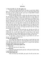
Consider a gearing transmission system with a
controller as depicted in Figure 1. The driving
motor provides a control torque
d
M
which is
transmitted to the load
c
M
through two wheel
gears 1 and 2 and two elastic shafts. Let
1
f
M
and
2
f
M
denote the friction moment on each shaft.
Both shafts have the same elasticity factor denoted
by
c
. Let
1
and
2
be the rotational angles of
corresponding shaft and
the backlash between
cogwheels. The Euler-Lagrange model of this
gearing transmission system is given as follows
(see, for example, [2]).
2 2
1 1 1 1 12 2 1
2 2
2 2 2 2 21 1 2
cos ( )
cos ( )
d f
c f
J cr i M M
J cr i M M
(1)
where
1 2
and
r r
are the outer radii of
corresponding wheels 1 and 2,
1
12 21
i i
is the
transmission rate of the two wheels and
1 2
, ,
d
J J J
are the inertia moments of wheel 1, wheel 2 and
the driving motor respectively and
1 1
d
J J J
denotes the sum of inertia moments of wheel 1
and the driving motor.
Figure 1. Configuration of a gearing transmission
system
While
1 2 12 21 1
, , , ,
J J i i r
and
2
r
in Euler-Lagrange
model (1) can be considered as known parameters,
the other parameters such as shaft
elasticity
,
c
friction moments
1 2
, ,
f f
M M
load
moment
,
c
M
backlash
are all uncertainties or
disturbances of the system.
2.2 States space model
In the following, all unknown constant parameters
of the model will be denoted by
k
, whereas
disturbances by
k
d
. By using
2 2 1 2 2
1 1 2 2
1 1 1 1 1 2 2 2 2 2
cos , cos
( , ) , ( , )
f c f
cr cr
M b d t M M b d t
where
1 2
,
b b
known constants,
1 2
,
unknown constants,
( )
1 1 1 1
1
, , , ,
T
p
,
( )
2 2 2 2
2
, , , ,
T
q
,
( )
k
x
th
k
derivative of
x
,
,
p q
finite positive integers,
1 1 2 2
( , ) , ( , )
d t d t
unknown disturbances,
the Euler-Lagrange model (1) becomes
1 1 1 1 12 2 1 1 1
1 1
2 2 2 2 12 1 2 2 2
( )
( )
d
J i M b d
J i b d
(2)
From the second equation of (2), it is easy to see
that
1 12 2 2 2 2 2 2 2
3 2 4 2 12 2 3
i J b d
i d
(3)
with
3 12 2 2 3 2 2 4 12 2 2
, ,
d i d J i b
and
1 3 2 4 2 12 2 4
(4)
1 3 4 2 12 2 5
2
i d
i d
(4)
where
4 3 5 4
,
d d d d
. From (2), (3) and (4), it follows
that
1
f
M
c
M
Load
c
c
d
M
1
2
2
f
M
M
Controller
1
2
1
2
Tuyển tập công trình Hội nghị Cơ điện tử toàn quốc lần thứ 6 27
Mã bài: 07
(4)
1 3 1 4 1 3 2 1 4 1 3 1 12 2
2
1 4 1 12 2 1 5 1 3 1 4 1
d
M J J b b J i
b i J d d b d d
Next, let states vector
x
, truncated states vector
x
, input control signal
u
, vector of unknown
constants
f
, unknown constant
g
and unknown
disturbance
( , )
d t
x
be defined as follows
1 2
2 2
3 2
4 2
x
x
x
x
x ,
2 2
3 2
4 2
x
x
x
x ,
d
u M
1 4 1 12
1 4 1 3 1 12
1 3
1 4 1 3
1
f
b i
b J i
J
J b
,
1 3
g
J
1 5 1 3 1 4 1
1 3
1
( , )
d t J d d b d d
J
x
The Euler-Lagrange model (2) of the gearing
transmission system, can now be rewritten in the
form of uncertain states model (5)
1
4
if 1 3
( , )
k k
T
f g
x x k
x d t u
x x
(5)
with
( , )
d t
x
being bounded by a number
0
,
that is
( , )
d t
x
for all
,
t
x
. (6)
3. Robust and Adaptive Tracking Controller
3.1 Sliding mode controller
Let
( )
w t
be the reference signal, so the reference
trajectory for system (5) will be
, , ,
T
w w w w
w
and the vector of reference error is
, , ,
T
e e e e
e
where
1 2
e w x w
.
To control the states vector
( )
t
x
of (5) to
asymptotically track the reference trajectory
( )
t
w
based on sliding mode control, first the following
sliding surface is used
1 2 3
( )
T
s e a e a e a e e
a e
(7)
where all elements
1 2 3
, ,
a a a
of vector
1 2 3
, , , 1
T
T
a a aa
are chosen such that the following polynomial
2 3
1 2 3
( )p a a a
(8)
will be Hurwitz. Note that, by using sliding
surface (7), in order to ensure the asymptotic
tracking performance
0
e
and
e
the nesecessary and sufficient condition is
( ) 0
s e
.
Thus, the initial tracking control aim can now be
replaced with
( ) 0
s e
and
( ) for 0
s e t
.
Now consider the following candidate control
Lyapunov function (CLF)
2
1
( )
2
V s e
(9)
with its derivative being given by
(4)
1 2 3 4
3
( ) (4)
1
( , ) .
i T
i f g
i
V ss s a e a e a e w x
s a e w d t u
x x
Therefore, if the following controller is used
3
1 ( ) (4)
1
sgn( )
k T
g k f
k
u a e w s
x ,
(10)
then
3
( ) (4)
1
( , ) sgn ( )
( , ) sgn ( )
0,
i T
i f g
i
V s a e w d u
sd t s s e
s d t s s e
s
x
x
x
which sufficiently ensures the boundedness of
( )
s e
as well as the asymptotic decay to zero of
( )
s e
.
3.2 Adaptive Parameters Adjustment
In practice, the controller (10), however, cannot be
used because of the unknown parameters
f
and
g
. To overcome this limitation, the certainty
equivalence principle will be employed.
First, the unknown constants
f
and
g
in (10)
are replaced by time functions
( )
f
t
and
( )
g
t
,
respectively, yielding
3
1 ( ) (4)
1
sgn( )
k T
g k f
k
u a e w s
x (11)
where
is any chosen constant .
28 Le Thi Thu Ha, Nguyen Thi Chinh, Nguyen Doan Phuoc
VCM2012
With this replacement, the derivative of the sliding
surface (7) is now given by
(4)
1 2 3
(4)
1 2 3 4
3
( ) (4)
1
3
( ) (4)
1
3
( ) (4)
1
3
( )
1
( , )
( , )
( , )
k T
k f g
k
k
k
k
T
f g g g
k T
k f g g
k
k
k
k
s a e a e a e e
a e a e a e w x
a e w d t u
a e w
d t u u
a e w d t u
a e
x x
x x
x x
(4)
sgn( )
( , ) sgn( )
( , ) sgn( )
T
f
T
f f g g
T
f g
w s
u d t s
u d t s
x
x x
x x (12)
where
f f f
and
g g g
.
It can be noted further that
f f
and
g g
. (13)
because of constancy of
f
and
g
.
Second, by using an adaptive CLF candidate
1 2
2 1 2
1 1
( ) ( ) ( )
2 2
1 1 1
2 2 2
T
f f f f g g
T
f f g
V V
s
F
F
where
3 3
F
R
is any symmetric positive definite
matrix and
is an arbitrary positive constant.
Figure 2. Configuration of the closed loop system
By using (12) and (13), one subsequently obtains:
1
1
1
1
1
( , ) sgn( )
1
( , ) sgn( )
1
( , ) sgn( )
T
f f g g
T
f g
T
f f g g
T
f g
T
f f g g
T
f f
V ss
s u d t s
s u d t s
sd t s s s
F
F
F
F
x x
x x
x x
1
g g
su
(14)
Now, by using the following adaptive adjustments
for the time functions
( )
f
t
and
( )
g
t
of
controller (11)
( )
( )
f
g
s e
s e u
F
x
(15)
the derivative
V
becomes negative definite
( , ) sgn( ) ( , )
0
V sd t s s s d t s
s
x x
which is sufficient for ensuring that ( )
s e
and
( ) 0
s e
.
3.3 Controller Design Procedure
Figure 2. shows the main configuration of the
closed loop system, in which the designed
controller, including sliding mode controller (11)
and adaptive parameters laws (15), always drives
the output
1 2
y x
to asymptotically converge
to any four times differentiable desired trajectory
( )
w t
.
To obtain this closed loop system’s tracking
performance, in summary, the following steps
should be executed.
Estimate of
according to (6)
Choose three constants
1 2 3
, ,
a a a
so that the
polynomial (8) is Hurwitz
Construct the sliding surface
( )
s e
according to (7)
Choose any symmetric positive defined matrix
3 3
F
R
and a positive constant
.
Construct the adaptive adjustor according to (15)
Construct the sliding mode controller according to
(11)
u
w
x
,
f g
Plant
(
2
)
Controller
(
11
)
Adjustor
(15)
Tuyển tập công trình Hội nghị Cơ điện tử toàn quốc lần thứ 6 29
Mã bài: 07
4. Numerical Example
Consider a gearing transmission system as
described in Figure 1. where
( , )
d t
x
is a white
noise with
0.1
d
and the reference signal is
given by
( ) sin(0.1 )
w t t
.
Let design parameters be chosen as follows:
3
50
F I
, where
3
I
is the unity matrix in
3 3
R
0.1
1 2 3
125, 75, 15
a a a
, sliding surface
constants
0.5
is infinite norm of disturbance
1
is parameter for controller (11)
The tracking error and the system output are
shown in Figure 3. and Figure 4. ; three elements
of the vector
f
and
g
from the adaptive
adjustors, are also given in Figure 5. and Figure
6. , respectively.
From the simulation results, it can be seen that the
system output asymptotically converges to the
desired trajectory even in the presence of the
unknown parameters
f
,
g
and the bounded
disturbance
( , )
d t
x
.
Figure 3. The tracking error
Figure 4. Desired trajectory and system output
0 10 20 30 40 50 60 70
-80
-60
-40
-20
0
20
40
60
80
100
Figure 5. Adjusted parameters
f
0 10 20 30 40 50 60 70
0
0.2
0.4
0.6
0.8
1
1.2
1.4
Figure 6. Adjusted parameter
g
0
10
20
30
40
50
60
70
-25
-20
-15
-10
-5
0
5
10
15
20
25
Figure 7. Desired trajectory and system output by
time dependent uncertainties
0 10 20 30 40 50 60 70 80 90 100
-1.6
-1.4
-1.2
-1
-0.8
-0.6
-0.4
-0.2
0
0.2
0.4
Figure 8. Adjusted parameters
[1]
f
compared with
[1]
( )
f
t
0 10 20 30 40 50 60 70
-1.5
-1
-0.5
0
0.5
1
1.5
f
( )
w t
2
( )
t
0 10 20 30 40 50 60 70
-0.2
-0.15
-0.1
-0.05
0
0.05
0.1
0.15
2
e w
30 Le Thi Thu Ha, Nguyen Thi Chinh, Nguyen Doan Phuoc
VCM2012
0 10 20 30 40 50 60 70
-2
-1.5
-1
-0.5
0
0.5
1
Figure 9. Adjusted parameters
[2]
f
compared with
[2]
( )
f
t
It should be noted that the adjusted parameters
f
and
g
do not tend to the actual values of
unknown parameters
f
and
g
. In fact, in this
example, the plant (5) was simulated with
1 2 3
T
f
and
1
g
.
However, this does not affect the tracking
performance of the system. In addition, although
the asymptotic tracking convergence of system is
theoretical proved under assumtion that
uncertainties
,
f g
are constants, this
performance is still keeping even in the case of
time dependent uncertain vector
( ), ( )
f g
t t
as the
experimental simulation results has shown in
Figure 7. Figure 10. , whichs are carried out for
system (5) with the time dependent functions of
three uncertainties:
[1] 1 0.4sin(0.5 )
f
t
[2] 1 0.2sin(0.5 )
f
t
[3] 1 0.2sin(0.5 )
f
t
0 10 20 30 40 50 60 70 80 90 100
-0.2
0
0.2
0.4
0.6
0.8
1
1.2
Figure 10. Adjusted parameters
[3]
f
compared with
[3]
( )
f
t
5. Conclusion
The adaptive and robust controller, which is
designed by using the procedure proposed in this
paper, obviously satisfies the tracking requirement
of the system. This satisfaction has been proved
theoretically and numerically. In fact, the
controller can effectively attenuate the disturbance
and suppess the effect of parameter uncertainties.
Note that although the tracking error is guaranteed
to be zero at its steady state, its value during the
transient period cannot be constrained in a
predetermined range. This limitation can be
avoided by using a barrier CLF instead of (9) and
choosing
1 2 3
, ,
a a a
of the sliding surface (7)
appropriately.
Furthermore, as a consequence of using sliding
mode control, there still exists the chattering in the
system. In oder to damp this undesired behavior,
the constant
should be chosen as small as
possible but not less than
. In the case, that the
constant
has to be choosen less than
, the
controller (11) can be revised as
3
( ) (4)
1
( , ) sgn( )
k T
k f
k
g
a e w d t s
u
x x
where
( , )
d t
x
is an estimate of
( , )
d t
x
such that
,
sup ( , ) ( , )
t
d t d t
x
x x
The function
( , )
d t
x
can be obtained easily by
using, for example, a neural network.
References
[1] Eutebach, T. and Pacas, J.M.: Damping of
torsional vibration in high dynamic drivers. 8.
European Conference on Power Electronics
and Applications EPE 99, 1999.
[2] Ha,L.T.T.: Modelling of transmission two-
weel gearing System. Reaserch report, TNUT,
2012.
[3] Hara, K.; Hashimoto, S.; Funato, H and
Kamiyama, K.: Robust comparison between
feedback based speed control system without
states observer in resonant motor drivers.
Power Electronics and Applications, 1997.
[4] Hori, Y.; Sawada, H. and Chun, Y.: Slow
Resonance Ratio Control for Suppression and
Disturcances Rejection in Torsional Systems.
IEEE trans. on Industial Electronics, Vol.46,
No.1, pp. 162-168, 1999.
[5] Kraftmueller, M: Adaptive Fuzzy Controller
Design. Atca Polytechnica Hungaria, Vol.6,
No.4, 2009.
[6] Krstic,M.; Kanellakopoulos,I.; Kokotovic,P.:
Nonlinear and Adaptive Control Design. John
Wiley & Sohn Inc., 1995.
Tuyển tập công trình Hội nghị Cơ điện tử toàn quốc lần thứ 6 31
Mã bài: 07
[7] Menon, K. and Krishnamurty: Control of low
friction and gear backlash in machine tool
feed drive systems Mechatronics 9, pp.33-52,
1999.
[8] Sugiura, K. and Hori, Y.: Vibration
Suppenssion in 2- and 3-Mass System based
on Feedback of Imperfect Derivative of the
Estimated Torsional Torque. IEEE trans. on
Industial Electronics, Vol.43, No.1, pp. 56-64,
1996.
[9] Szabat,K. and Orlowska,K.T.: Vibration
suppenssion in two mass drive system using PI
speed controller and additional feedbacks -
comparative study. IEEE trans. on Industial
Electronics, Vol.54, No.2, pp. 1193-1206,
2007.
[10] Szabat,K. and Orlowska,K.T.: Performance
Improvement of the Indusrial Drivers with
mechanical Elasticity using nonlinear
adaptive Kalman Filter. IEEE trans. on
Industial Electronics, Vol.55, No.3, pp. 1075-
1084, 2008.
[11] Utkin, V.: Sliding Modes in Optimization and
Control. Springer Verlag New York, 1992.
[12] Walha, L.; Fakhfakh, T. and Haddar, M.:
Nonlinear dynamic of two stage gear system
with mesh stiffness fluctuation, bearing
flexibility and backlash. Mechanism and
Machine 44, pp.1058-1069, 2009.
Le Thi Thu Ha received B.S. and
M.S. degrees from Thai Nguyen
University of Technology in 1999
and 2003 respectively, all in
automation technology. Since
2000 she has been with Electrical
Engineering Department at TNUT
Viet Nam, where she is nominated
as head of department in 2008. Her research
interests include modeling of mechanical systems
and controller design for Euler-Lagrange systems
Nguyen Thi Chinh received her
B.S. degree from Hanoi University
of Science and Technology in
2003 and M.S. degree from Thai
Nguyen University of Technology
in 2007. Since 2003 she is
working as Uni. lecture in
Industrial Automation Department of TNUT Viet
Nam. Her research interests are Fuzzy Control and
Neural Networking.
Nguyen Doan Phưoc received his
Dipl Ing. and Dr Ing. degree
from Institut für Steuerungs- und
Regelungstheorie, TU Dresden,
Germany in 1982 and 1994. From
1994 to 1996 he has worked with
Fraunhofer Institut Dresden on
Modelling and Simulation. Since 1997 he has
been with Automatic Control Department at
HUST Viet Nam, where he is nominated as
associate professor in 2003. His research interests
are adaptive and robust control, optimization and
optimal control.