Investigation of Mg doping profile in the pcladding layer for highbrightness AlGaInPbased light emitting diodes.
Bạn đang xem bản rút gọn của tài liệu. Xem và tải ngay bản đầy đủ của tài liệu tại đây (523.54 KB, 4 trang )
Delivered by Publishing Technology to: ?
IP: 93.91.26.29 On: Thu, 30 Jul 2015 17:15:34
Copyright: American Scientific Publishers
Copyright © 2014 American Scientific Publishers
All rights reserved
Printed in the United States of America
Article
Journal of
Nanoscience and Nanotechnology
Vol. 14, 6124–6127, 2014
www.aspbs.com/jnn
Investigation of Mg Doping Profile in the
p-Cladding Layer for High-Brightness
AlGaInP-Based Light Emitting Diodes
Hwa Sub Oh
1
, Ho Soung Ryu
1 3
, Joon Mo Park
1
, Hyung Joo Lee
2
, Young Jin Kim
2
,
In Kyu Jang
2
, Ji Hoon Park
2
, Joon Seop Kwak
3
, and Jong Hyeob Baek
1 ∗
1
LED Device Research Center, Korea Photonics Technology Institute,
971-35 Wolchul-dong, Buk-gu, Gwangju, Korea
2
Process Engineering Department, Kodenshi Auk Incorporation,
513-37 Eoyang-doing, Iksan city, Chonbuk, Korea
3
Department of Printed Electronics Engineering, Sunchon National University,
Chonnam 540-742, Korea
We investigated 590 nm light-emitting diodes appropriate for full-color display applications in terms
of their electrical and optical behaviors during operation according to their Mg doping profile in the
p-cladding layer. As the hole concentration in the “b” zone of the p-cladding layer is increased
from 34 × 10
17
to 67 × 10
17
, the light output power increases by 41% due to the enhancement
of the hole injection into the active region and also due to the minimization of the carr ier overflow
problem. However, at an oversaturation of Mg doping with excess [Cp
2
Mg]/[III] in the “b” zone, the
internal quantum efficiency degrades because of the decrease in hole concentration because of the
oversaturated material problem.
Keywords:
Mg Doping Profile, p-Cladding Layer, AlGaInP-Based LED.
1. INTRODUCTION
Recently, AlGaInP-based light-emitting diodes (LEDs)
have experienced an impressive evolution in both device
performance and market volume. In particular, high-
brightness LEDs are gaining interest for use in commercial
applications such as automotive lighting, full-color dis-
plays, and general illumination. To increase their util-
ity in these applications, improved performance such
as shorter wavelengths and high-powered devices have
been pursued.
1–5
However, (Al
x
Ga
1−x
05
In
05
P heterostruc-
tures have a small conduction band offset that limits
their electron confining potential.
6
This weaker electron
confinement subsequently leads to electron heterobarrier
leakage in AlGaInP heterostructure LEDs, especially in
short-wavelength devices, where a fraction of the electrons
injected into the active region have a sufficient thermal
energy to escape into the p-cladding layer. To overcome
this problem, AlGaInP-based LED structures require an
∗
Author to whom correspondence should be addressed.
optimized doping profile in the p-cladding layer in order to
prevent carrier overflow and to gain a higher light output
power (P
out
. In the field of AlGaInP-based LEDs that
emit a short peak wavelength at around 590 nm, how-
ever, the effects of the doping profile in the p-cladding
layer on LED performance has yet to be systematically
studied.
In this study, we investigate the behaviors of electri-
cal and optical characteristics according to their Mg dop-
ing profile in the p-cladding layer by analyzing device
performances.
2. EXPERIMENTAL DETAILS
We conducted metal-organic vapor phase epitaxy
(MOVPE) to grow LED structures on a 2-in (100)
GaAs substrate that was tilted 10
toward 011 to sup-
press spontaneous ordering in the GaInP and AlGaInP
epilayers.
6
Here, trimethylaluminum (TMAl), trimethyl-
gallium (TMGa), and trimethylindium (TMIn) were used
6124
J. Nanosci. Nanotechnol. 2014, Vol. 14, No. 8 1533-4880/2014/14/6124/004 doi:10.1166/jnn.2014.8320
Delivered by Publishing Technology to: ?
IP: 93.91.26.29 On: Thu, 30 Jul 2015 17:15:34
Copyright: American Scientific Publishers
Oh et al. Investigation of Mg Doping Profile in the p-Cladding Layer for High-Brightness AlGaInP-Based Light Emitting Diodes
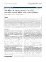
Figure 1. Schematic of LED structures having different Mg doping pro-
files in the p-cladding layer.
as the group-III sources; phosphine (PH
3
and arsine
(AsH
3
were the group-sources, and disilane (Si
2
H
6
and
biscyclopentadienylmagnesium (Cp
2
Mg) were the n- and
p-type doping sources, respectively. The growth temper-
ature was set at 700
C, for a growth rate of about
1.5 m/h. The multi-quantum well (MQW) structures for
emitting a 590 nm peak wavelength consisted of 4.5 nm
(Al
02
Ga
08
05
In
05
P quantum wells separated by 30 nm
(Al
05
Ga
05
05
In
05
P barrier layers, which were sandwiched
between two Al
05
In
05
P cladding layers. To improve the
LED performance relative to the Mg doping concentra-
tion, the p-cladding layer was divided into three zones:
“a”, “b”, and “c” zones. In addition, a 10-m-thick p-GaP
window layer capped the p-cladding layer in order to eval-
uate the actual device performance. Schematics of the LED
structures are depicted in Figure 1.
Table I presents the detailed Mg doping profiles for
the three zones of the p-cladding layer in the LED struc-
tures. Note that the “a” zone in the p-cladding layer is
intentionally left undoped and that the “c” zone is rela-
tively lightly doped with 10 ×10
−4
[Cp
2
Mg]/[III] in order
to prevent Mg diffusion into the active region. To inves-
tigate and optimize the hole injection into the active
region and to prevent electron overflow, the “b” zone in
the p-cladding layer is doped with [Cp
2
Mg]/[III] values
of 10 × 10
−4
,20 × 10
−4
,30 × 10
−4
, and 50 × 10
−4
in
the Test 1, Test 2, Test 3, and Test 4 LED structures,
respectively. To determine the hole concentration in the
p-cladding layer according to the [Cp
2
Mg]/[III] value,
electrochemical capacitance–voltage (ECV) measurements
at 300 K were performed. To evaluate the devices, the
Table I. Detailed Mg doping profiles for “a,” “b,” and “c” zones in the p-cladding layer of LED structures.
Mg Doping profile at p-cladding layer
“a” zone “b” zone “c” zone
No. [Cp
2
Mg]/[III] Hole conc. [cm
−3
] [Cp
2
Mg]/[III] Hole conc. [cm
−3
] [Cp
2
Mg]/[III] Hole conc. [cm
−3
]
Test 1 0 − 10 × 10
−4
34 × 10
17
10 × 10
−4
34 × 10
17
Test 2 0 − 20 × 10
−4
51 × 10
17
10 × 10
−4
34 × 10
17
Test 3 0 − 30 × 10
−4
67 × 10
17
10 × 10
−4
34 × 10
17
Test 4 0 − 50 × 10
−4
53 × 10
17
10 × 10
−4
34 × 10
17
wafers were sectioned into 300 m × 300 m chips,
with 80-m-diameter metal contacts located on the top
p
+
-contact layer. After dicing, the chips were mounted
onto TO-18 headers with no epoxy encapsulation before
being measured using a large-area Si photodiode that was
placed on top of the device.
3. RESULTS AND DISCUSSION
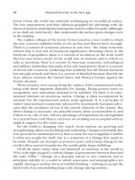
Figure 2 presents the typical current–voltage (I–V ) char-
acteristics and light output power (P
out
of LEDs having
different Mg doping profiles in the p-cladding layer. The
I–V characteristics in the “b” zone in the p-cladding layer
show similar behaviors regardless of the p-doping concen-
tration. These data indicate that the Mg doping level in
the “b” zone is not significantly affected by the operating
voltage, in terms of device performance.
Figure 2(b) then shows the light output-current charac-
teristics of LEDs having different Mg doping levels in the
“b” zone. In addition, the relative increase of P
out
(RIP) of
the same LEDs at a 200 mA operating current is shown
in the figure inset. As the [Cp
2
Mg]/[III] value in the “b”
zone is increased from 10 × 10
−4
to 30 × 10
−4
, the RIP
increases from 1.0 to 1.4, though at a further increase of
[Cp
2
Mg]/[III] to 50 × 10
−4
, the RIP degrades to 1.3.
The improvement of internal quantum efficiency is due
to the fact that the highly p-doped “b” zone increases the
potential barrier in the p-cladding layer, which minimizes
the electron overflow problem, and the improved hole con-
ductivity helps to enhance the hole injection into the active
region.
7
The RIP decrease in the Test 4 LED structure indi-
cates that the excess [Cp
2
Mg]/[III] deteriorates the internal
quantum efficiency. As such, it is important to optimize
the [Cp
2
Mg]/[III] value in the p-cladding layer in order to
improve the light output power.
One possible explanation for the decreased light out-
put of the LEDs under an excess [Cp
2
Mg]/[III] value
is the degradation of the active region by Mg diffu-
sion. Meneghesso et al.
8
reported that the degradation of
optical power is accompanied by both an increase of a
generation-recombination current at a low forward bias
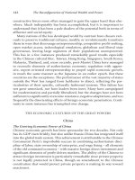
and an increase of the device ideality factor. To exam-
ine the influence of Mg diffusion into the active region,
the I–V characteristics plotted on a log–log scale and the
ideality factor of LEDs with different Mg doping profiles
J. Nanosci. Nanotechnol. 14, 6124–6127, 2014 6125
Delivered by Publishing Technology to: ?
IP: 93.91.26.29 On: Thu, 30 Jul 2015 17:15:34
Copyright: American Scientific Publishers
Investigation of Mg Doping Profile in the p-Cladding Layer for High-Brightness AlGaInP-Based Light Emitting Diodes Oh et al.
Current [mA]
Voltage [V]
Test 1
Test 2
Test 3
Test 4
0 50 100 150 200 250 300
0
200
400
600
800
1000
1200
1400
Test 1 Test 2 Test 3 Test 4
0.8
1.0
1.2
1.4
1.6
Relative increase of P
out
P
out
[a.u.]
Current [mA]
Test 1
Test 2
Test 3
Test 4
0
20
40
60
80
100
0.0 0.4 0.8 1.2 1.6 2.0 2.4
(a)
(b)
Figure 2. (a) Forward I–V characteristics and (b) light output power of
LEDs having different Mg doping profiles in the p-cladding layer. The
inset in (b) shows the relative increase of brightness for the same LEDs.
at p-cladding layer are shown in Figure 3. However, it
should be noted that no leakage current increase at a
low bias was observed. In addition, the LEDs with dif-
ferent Mg doping levels in the “b” zone did not induce
0.0 0.4 0.8 1.2 1.6 2.0 2.4
Test 1 Test 2 Test 3 Test 4
1.6
1.7
1.8
1.9
2.0
Ideality factor
Current [mA]
Voltage [V]
Test 1
Test 2
Test 3
Test 4
1E-7
1E-6
1E-5
1E-4
1E-3
0.01
0.1
1
10
100
Figure 3. Forward I–V characteristics plotted on a log–log scale of
LEDs having different Mg doping profiles in the p-cladding layer. The
inset shows the ideality factors of the same LEDs.
significant changes in ideality factors. Hence, these results
imply that the decrease in the light output of LEDs with
an excess [Cp
2
Mg]/[III] value cannot be explained sim-
ply based on degradation caused by Mg diffusion into
the active region. Indeed, these results indicate that the
intentionally undoped “a” zone and relatively low-doped
“c” zone efficiently prevent Mg diffusion into the active
region.
Another possible explanation for the decreased light out-
put of the LEDs with excess [Cp
2
Mg]/[III] in the “b”
zone is directly related to the decreased hole concentra-
tion. The hole concentration of the p-type Al
05
In
05
P layer
measured using the ECV shows that as the [Cp
2
Mg]/[III]
value is increased from 10 × 10
−4
to 30 × 10
−4
, the hole
concentration increases from 34 × 10
17
to 67 × 10
17
, and
that at a further increase to 50 × 10
−4
, the hole concen-
tration decreases to 53 × 10
17
due to the oversaturated
material problem.
9
These results indicate that the hole
concentration at the “b” zone in the p-cladding layer is
directly influenced by improvement in the spontaneous
light-emitting efficiency and that carefully optimizing the
[Cp
2
Mg]/[III] value is important for attaining the high-
est hole concentration—and thereby improving the device
performance.
4. CONCLUSION
To make 590 nm high-brightness LEDs that are appro-
priate for full-color display applications, we studied the
electrical and optical behaviors of device performances
according to their Mg doping profile in the p-cladding
layer. As the [Cp
2
Mg]/[III] value in the “b” zone was
increased from 10 × 10
−4
to 30 × 10
−4
, the light output
power increased by 41% due to the enhanced hole injec-
tion into the active region and also by minimization of the
carrier overflow problem. In addition, the oversaturation
of Mg doping in the “b” zone with excess [Cp
2
Mg]/[III]
deteriorated the internal quantum efficiency by decreas-
ing the hole concentration. As a result, by evaluating the
I–V characteristics and ideality factors, we found that the
intentionally undoped “a” zone and relatively low-doped
“c” zone efficiently acted to prevent Mg diffusion into the
active region.
Acknowledgment: This work was supported by a
Korea Research Foundation Grant from the ATC project
(No. 10035863) provided by the Ministry of Knowledge
Economy, Korea.
References and Notes
1. J. W. Seo, H. S. Oh, J. S. Kwak, H. D. Song, K. W. Park, D. H.
Park, S. W. Ryu, and Y. H. Park, J. Korean Phys. Soc. 55, 314
(2009).
2. P. Blood, Mat. Sci. Eng. B 66, 174 (1999).
3. C. M. Reaves, R. I. Pelzel, G. C. Hsueh, W. H. Weinberg, and S. P.
DenBaars, Appl. Phys. Lett. 69, 3878 (1996).
6126 J. Nanosci. Nanotechnol. 14, 6124–6127, 2014
Delivered by Publishing Technology to: ?
IP: 93.91.26.29 On: Thu, 30 Jul 2015 17:15:34
Copyright: American Scientific Publishers
Oh et al. Investigation of Mg Doping Profile in the p-Cladding Layer for High-Brightness AlGaInP-Based Light Emitting Diodes
4. M. Eichfelder, W. M. Schulz, M. Reischle, M. Wiesner, R. Robach,
M. Jetter, and P. Michler, Appl, Phys. Lett. 95, 131107
(2009).
5. H. S. Oh, S. M. Kim, J. H. Joo, J. H. Baek, and J. S. Kwak, J. Nanosci.
Nanotechnol. 11, 1503 (2011).
6. J. Johansson, W. Seifert, T. Junno, and L. Samuelson, J. Cryst. Growth
195, 546 (1998).
7. P. Blood, Mat. Sci. Eng. B66, 174 (1999).
8. G. Meneghesso, S. Levada, R. Pierobon, F. rampazzo, E. Zanoni,
A. Cavallini, A. Castaldini, G. Scamarcio, S. Du, and
I. Eliashevich, IEDM Technical Digest, IEEE, San Francisco (2002),
p. 103.
9. G. J. Bauhuis, P. R. Hageman, and P. K. Larsen, J. Crystal Growth
191, 313 (1998).
Received: 17 March 2013. Accepted: 17 April 2013
J. Nanosci. Nanotechnol. 14, 6124–6127, 2014 6127