Proceedings VCM 2012 114 xây dựng hệ điều khiển véc tơ cho động cơ tự nâng kiểu mới
Bạn đang xem bản rút gọn của tài liệu. Xem và tải ngay bản đầy đủ của tài liệu tại đây (644.1 KB, 7 trang )
834 Nguyen Quang Dich and Nguyen Huy Phuong
VCM2012
Development of Vector Control System for a Novel Self-Bearing Motor
Xây dựng hệ điều khiển véc tơ cho động cơ tự nâng kiểu mới
Nguyen Quang Dich and Nguyen Huy Phuong
Hanoi University of Science and Technology
e-Mail:
Abstract:
Magnetic bearing motors have many advantages such as no friction loss, no abrasion, no lubrication and so
forth. However, they are not widely used due to their high cost, complex control and large size. In order to
solve these problems, a self-bearing motor is a reasonable trend in current researches. This paper will introduce
a salient permanent magnet type axial-gap self-bearing motor (ASBM), which is an electrical combination of
an axial thrust bearing and an axial-flux motor, as well as the method of controlling axial position and rotating
speed of the ASBM. First, the axial force and the motoring torque are analyzed theoretically and then the
control method is derived. In order to confirm the proposed technique, an ASBM has been made and tested.
The experimental results confirm that the ASBM works stably with the proposed vector control. Moreover, the
rotating torque and the axial force can be controlled independently as well.
Tóm tắt:
Các động cơ sử dụng ổ từ thường có các ưu điểm như là không có tổn hao do ma sát, không có hao mòn,
không cần bôi trơn Tuy nhiên động cơ dùng ổ từ lại thường không được sử dụng phổ biến hiện nay do chúng
thường có kích thước lớn, hệ điều khiển phức tạp và giá thành cao. Để giải quyết những vấn đề này, động cơ tự
nâng –động cơ điện có tích hợp chức năng của ổ từ - đang được nhiều nhà nghiên cứu quan tâm. Bài báo này
sẽ giới thiệu một loại động cơ tự nâng kích thích vĩnh cửu loại từ trường dọc trục (ASBM) cũng như phương
pháp điều khiển vị trí dọc trục và tốc độ quay của nó. Đầu tiên, lực nâng và mô men quay được phân tích về
mặt lý thuyết, sau đó phương pháp điều khiển được giới thiệu. Để minh chứng cho phương pháp điều khiển
được giới thiệu ở trên, động cơ ASBM được chế tạo và thử nghiệm. Kết quả thực nghiệm chỉ ra rằng ASBM
hoạt động ổn định với phương pháp điều khiển vector được giới thiệu. Hơn nữa, mô men quay và lực nâng dọc
trục có thể được điều khiển một cách độc lập với nhau.
Nomenclature
Name Unit Description
g and z mm Air gap and
displacement
g
0
mm Air gap at equilibrium
point
F N Axial levitation force
T Nm Rotating torque
L
sd
, L
sq
H d and q-axis phase
inductances of stator
L
sl
, L
fl
H Leakage phase
inductances of stator
and rotor
sd
,
sq
Wb d and q-axis fluxes of
stator
m
Wb
Flux linkage
f
Wb
Permanet magnet flux
i
d
, i
q
A d and q-axis controlled
currents
i
do
A Bias current
W Magnetic field energy
i
f
A Fictious rotor current
Acronyms
PM Permanet Magnet
ASBM Axial-gap Self-bearing Motor
1. Introduction
Recently, magnetic bearing motors have been
designed to overcome the deficiencies of
conventional mechanical bearing motors. They
show the abilities to work in vacuum with no
lubrication and no contamination, or to run at high
speed, and to shape novel rotor dynamics.
Therefore, they are very valuable machines with a
number of novel features, and with a vast range of
diverse applications [1].
The conventional magnetic bearing motor
usually has structures like a rotary motor installed
between two radial magnetic bearings or
mechanical combination of rotary motor and radial
magnetic bearing as shown in Figs. 1 and 2, in
Tuyển tập công trình Hội nghị Cơ điện tử toàn quốc lần thứ 6 835
Mã bài: 177
which, two radial magnetic bearings create radial
levitation forces for rotor, whilst an axial magnetic
bearing produces a thrust force to keep the rotor in
right axial position to the stator. However, these
types of magnetic bearing motor are large size,
heavy weight and complex control, which cause
problems in some applications that have limit
space [2],[3]. For this reason, simpler and smaller
construction and less complex control system are
desirable.
The Earnshaw’s theorem shows that a rotor can
be supported stably by static magnetic field when
being controlled by one axis actively. Therefore, if
a stator has capabilities of producing a rotating
torque and controlling one axis actively, the non-
contact levitation can be realized in small and
simple structure. Based on this feature, an axial-
gap self- bearing motor (ASBM) has been
introduced as in Fig. 3. It is an electrical
combination of an axial flux motor and an axial
magnetic bearing, which is simpler in structure
and control than the conventional magnetic
bearing motor since hardware components can be
reduced [4],[5],[6]. This type of motor can be
realized as induction (IM) [5], or permanent
magnet (PM) motor [6],[7],[8]. The PM type
motor is specially paid attention, due to its high
power factor, high efficiency and simplicity in
production.
In this paper, the salient 2-pole ASBM with
double stators is introduced. The closed-loop
vector control method for the axial position and
the speed is developed in the way of eliminating
the influence of each other. Moreover, the
compensational method for reference currents
based on the difference between d and q axis
inductances is also recommended. In order to
confirm the presented technique, an experimental
setup has been made and tested.
2. Modeling and Control
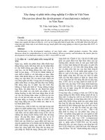
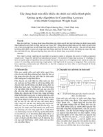
Fig. 4 illustrates the principle structure of the
proposed axial gap self-bearing motor. The radial
motions x, y, θ
x
, θ
y
of the rotor are constrained by
radial magnetic bearings such as the repulsive
bearing. Only rotational motion and translation of
rotor along z axis are considered. The motor has
two degrees of freedom.
The rotor is a flat disc with permanent magnet
(PM) inserted on two faces of disc to create a
salient-pole rotor. Two stators, one in each side of
the rotor, have three-phase windings to generate
the rotating magnetic flux in the air gap that
produces the motoring torque T
1
and T
2
to the rotor
and generates the attractive force between the rotor
and the stators F
1
and F
2
. The total motoring
torque T is sum of those torques and the axial
force F is different between two attractive forces.
To get mathematical model of the ASBM, first,
the axial force F
s
and motoring torque T
s
are
calculated for one stator. Similar to the
conventional permanent magnet motor, the
mathematical model of the ASBM is also
presented in rotor field oriented reference frame or
Fig. 4. The principle structure of the axial gap self
bearing motor.
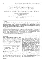
u-vw -w v -u w
u
d wqv
2 2 2
Rotor
Stator
Fig.5. Coordinates
Fig. 1. Structure of conventional magnetic bearing motor.
Fig.2. Structure of radial combined magnetic bearing
motor
Fig.3. Structure of axial gap self bearing motor
836 Nguyen Quang Dich and Nguyen Huy Phuong
VCM2012
so-called d, q coordinates as indicated in Fig. 5,
where the d axis is aligned with the center lines of
permanent magnets and the q axis between the
magnets. The axes u, v and w indicate the
direction of the flux produced by corresponding
phase windings. The power invariant principle is
used for transforming between coordinates. The
phase difference between the u axis and d axis is
an angular position θ of the rotor or the rotor flux
vector.
Since the permanent magnet with unity
permeability is used, the rotor is salient type,
hence the self phase inductance of the stator is
dependent on the rotor angular position, which
means d axis inductance is different from q axis
inductance. Furthermore, the self phase
inductance is a function of the air gap g between
rotor and stator. Normally, the self phase
inductance is inversely proportional to the air gap,
so the d and q axis phase inductance of the stator
windings may be approximated by
0
0
3
2
3
2
sd
sd sl
sq
sq sl
L
L L
g
L
L L
g
(1)
in which
0 0
sd sq
L ,L
are effective inductances per unit
gap in d and q axis, and L
sl
is leakage inductance.
Then, the stator voltage and flux of the ASBM
in the d,q coordinates can be expressed in the
following equations:
sd
sd s sd sd sq sq
sq
sq s sq sq sd sd m
sd sd sd m
sq sq sq
di
u R i L L i
dt
di
u R i L L i
dt
L i
L i
(2)
with
m
is the flux linkage caused by rotor
magnetic field. For simplicity, the permanent
magnet of the rotor is replaced by an equivalent
winding with current i
f
and inductance of rotor
winding L
f
. It can be expressed only in d axis as
follows
f fd f f m sd
i L L i
(3)
with
0
3
2
sd
f fl
L
L L
g
(4)
and mutual inductance
0
3 / 2
m sd
L L g
(5)
From (1) to (3), the magnetic energy in the air
gap is calculated as
( ) / 2
f f sd sd sq sq
W i i i
(6)
Therefore, the attractive force of a stator is
received by derivative of magnetic energy with air
gap
2
0
2
0
2 2
3
3
4 4
sq
sd
s sd f sq
L
LW
F i i i
g g g
(7)
and motoring torque of a stator is derived by using
Fleming left hand rule
0 0
0
( )
3 ( )
3
2 2
s sd sq sq sd
sd sq
sd
f sq sd sq
T P i i
P L L
PL
i i i i
g g
(8)
with P is number of pole pairs.
From (8) we can see that output torque is a
combination of excitation torque and reluctance
torque. That means, in every operation mode, the
motor has to produce an additional torque to
compensate the reluctance torque. In the non-
salient pole rotor, this reluctance torque can be
ignored to make control system become more
simply. But in the salient pole rotor when the
reluctance torque can reach the relative high
amplitude, the neglect of this torque component
will reduce the quality of system, especially in
operation mode with axial load (i
d
≠ 0).
From (7) and (8)
1
F
and
1
T
are calculated by
substituting
0
g g z
,
1
sd d
i i
and
1
sq q
i i
, and
2
F
and
2
T
are calculated by substituting
0
g g z
,
2
sd d
i i
and
2
sq q
i i
. Thus, the total axial force F
and torque T are given by:
2 1
F F F
(9)
1 2
T T T
(10)
here,
0
g
is the axial gap at the equilibrium point
and z is the displacement.
For linearization at the equilibrium point (z = 0)
we expand (9) and (10) into Mac Laurin series and
take the first order term, the result is:
1 2 2 1
0
1 1 2 2 2 2 1 1
0
T q q T q q
R d q d q R d q d q
z
T K i i K i i
g
z
K i i i i K i i i i
g
(11)
2 2
2 2
2 1 2 1
2 2
2 2
2 1 2 1
0 0
2 2
Fd d f d f Fq q q
Fd d f d f Fq q q
F K i i i i K i i
z z
K i i i i K i i
g g
(12)
Tuyển tập công trình Hội nghị Cơ điện tử toàn quốc lần thứ 6 837
Mã bài: 177
in which
2 2
0 0 0 0
3 / 4 and 3 / 4
Fd sd Fq sq
K L g K L g
are
force factors,
0 0
3 /2
T sd f
K PL i g
and
0 0 0
3 / 2
R sd sq
K L L g
are torque factors.
To increase the total moment twice the
component moment created by one stator, the
moment-generated current must be same direction
and value. In order to keep the rotor in right
position between two stators, the forces acting on
rotor from both sides must be same value but
inverse, i.e. under the effect of axial load, if the
force-generated current of one side increases then
that current of other side has to decrease the same
amount, correspondingly. The rotating torque can
be controlled effectively by using q-axis current,
and the axial force can be controlled by changing
the d-axis current. We suppose that
1 2
1 0
2 0
q q q
d d d
d d d
i i i
i i i
i i i
(13)
with i
d0
is an offset current, and the value can be
zero or a small value around zero, then by
inserting (13) into (11) and (12), we receive
0 0
0
2 2 2 /
T q R d q R d q
eff rl rlz
T K i K i i K i i z g
T T T
(14)
2 2 2 2
0 0
0
0
4 ( ) 2
+4 ( )
Fd d d f Fd f d Fq q
Fd f d d
z
F K i i i K i i K i
g
K i i i
(15)
From (14), the total torque consists of three
components:
The first component 2
eff T q
T K i
is the efficient
torque, this is main component of the output
torque.
The second one
0 0
2
rl R d q
T K i i
is the reluctance
torque caused by bias current i
d0
. Therefore, if we
can assure that
1 2
d d d
i i i
i.e.
0
0
d
i
then this
reluctance torque is eliminated.
The last one
0
2 /
rlz R d q
T K i i z g
is reluctance
torque caused by current i
d
under the effect of the
displacement z. When the displacement is well
controlled to be zero, or very small in comparison
with air gap at the equilibrium point g
0
, the
influence of this component can be neglected.
Then the total torque becomes as follows
2
T q
T K i
(16)
By using above control law, we also receive the
axial force as follows
4
Fd f d
F K i i
(17)
Obviously, the effect of the inductance
difference to axial force is also vanished.
From (16) and (17), it is easy to see that the total
torque can be controlled with the quadrate axis
current and axial force can be controlled with the
direct axis current. And in combination with (1)
the mathematic model of the ASBM is totally
constructed with voltage, force and torque
equations. It is supposed that they are simple linear
equations, so the control system can be easily
implemented with the conventional controllers.
For simplicity, it is assumed that the radial
motion of the rotor is restricted by ideal radial
bearings. Therefore, the axial motion of the rotor
is independent from radial motion. The dynamic
equation of the axial motion of the rotor is
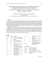
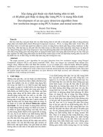
Fig. 6. The control scheme of the axial gap self bearing motor.
838 Nguyen Quang Dich and Nguyen Huy Phuong
VCM2012
F mz
(18)
where m is mass of moving part, and F is the axial
force shown in (15). Then by substituting (15) into
(18), we receive
2 2 2
0
4 4 ( ) 4
Fd f d Fd d f Fq q
z
mz K i i K i i K i
g
(19)
or summarized as
z m d
mz K z K i
(20)
with
2 2 2
4 ( ) 4
z Fd d f Fq q
K K i i K i
is stiffness of
the ASBM and 4
m Fd f
K K i
is force gain. It is
easy to realize that K
z
is negative, which means
this system is unstable. To stabilize the system, the
controller with derivative component must be
used. Assuming that, the proportional derivative
controller (PD) is used, the output of the controller
will represent the direct axis reference current, i.e.
d p d
i K z K z
(21)
with K
p
and K
d
are proportional and derivative
constant of the axial position controller. By
substituting (21) into (20), we get
0
m d z m p
mz K K z K K K z
(22)
The necessary condition for the system
becomes stable only when all constant coefficients
of the polynomial function are the same sign.
Therefore, if K
d
> 0, the proportional constant
must satisfy the condition
2 2 2
( )
Fd d f Fq q
z
p
m Fd f
K i i K i
K
K
K K i
(23)
to ensure that the system is stable.
Actually, there has steady-state error when only
PD controller is used, hence to remove the steady-
state error, the PID controller should be used.
As stated above, the motoring torque of the
ASBM can be controlled by q-axis current (i
q
),
while the axial force can be controlled by d-axis
current (i
d
). Therefore, the control scheme
proposed for the ASBM drive is shown in Fig. 6.
The axial displacement from the equilibrium
point along the z-axis, z, can be detected by the gap
sensor. The detected axial position is compared
with the axial position command z
ref
, then the error
is inserted in the axial position controller R
z
. The
output of the axial position controller is used for
calculating d-axis reference current with
compensation procedure from (15). Position
command z
ref
is always set to zero to make sure the
rotor is right in the midpoint between the two
stators. The d-axis reference currents for the two
stator windings i
d1ref
and i
d2ref
can be generated by
using the offset current i
d0
subtracting and adding
i
dref
respectively. In this paper, the value of the
offset current is zero.
The rotor speed detected from encoder is
compared to the reference speed, then, the
difference is input of the speed controller R
ω
. The
output of the speed controller is used for
calculating the q-axis reference current by using
(14), the q-axis reference currents for the two stator
windings are same with this current.
The motor currents in the two-phase stator
reference frame α,β are calculated by the
measurement of two actual phase currents.
Therefore, the d,q components are obtained using
the rotor position from encoder. The quadrate
components are controlled to the reference value
which is given by the speed controller, while the
direct components are controlled to the reference
value which is given by the axial position
controller. The outputs of the current controllers,
representing the voltage references, are afterward
directed to the motor through inverters using the
Pulse Width Modulation (PWM) technique, once
an inverse transformation from the rotating to the
three phase stator referent frame has been
performed. All controllers are standard PI
controllers except axial position one (PID).
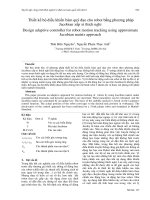
3. Implementation and Results
3.1 Hardware
In order to confirm the proposed control method
for the PM type ASBM, an experimental setup was
set up which is shown schematically in Fig. 7. The
rotor disc has a diameter of 50 mm and two
neodymium iron magnets with the thickness of
1mm for each side are inserted into its surfaces to
create one pole pair. For experimental simplicity,
the rotor is supported by two radial ball bearings in
order to restrict the radial motion of the rotor.
The stator has a diameter of core 50 mm and six
concentrated wound poles, each with 200 coil
turns. The stators can slide on linear guide to
ensure the same desired air gap between rotor and
two stators. A DC generator (Sanyo T402) is
installed to give the load torque. In order to
measure the rotor angle and the axial position, a
rotary encoder (Copal RE30D) and an eddy-
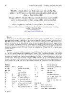
Fig. 8. Picture of the experiment setup.
Tuyển tập công trình Hội nghị Cơ điện tử toàn quốc lần thứ 6 839
Mã bài: 177
current-type displacement sensor (Sentec HA-
101S) are installed, respectively.
The control hardware of the ASBM drive is
based on a dSpace1104 board dedicated to control
of electrical drives, which includes PWM units,
general purpose input/output units (8 ADC and 8
DAC) and encoder interface. The DSP reads the
displacement signal from the displacement sensor
via an A/D converter, and the rotor angle position
and speed from the encoder via an encoder
interface. Two motor phase currents are sensed,
rescaled, and converted to digital values via an
A/D converter. Then, the dSpace1104 calculates
reference currents using the rotation control and
axial position control algorithms and send its
commands to three-phase inverter board. The
ASBM is supplied by two three-phase PWM
inverters with switching frequency of 40 kHz.
The image of the experimental setup is
presented in Fig. 8 and the parameters of the
ASBM is shown in table 1.
Table 1 Parameters of the ASBM
Stator phase
resistor
Rs = 2.6Ω
Stator phase d-
axis inductance
per unit air gap
6
8.2 10 Hm
sd0
L
Stator phase q-
axis inductance
per unit air gap
6
9.6 10 Hm
sq0
L
Leakage
inductance
3
6 10 H
sl
L
Air gap at
equilibrium point
0
1.7
g mm
Rotor mass m = 0.235 kg
Rotor inertia J =
0.000086kgm
2
Rotor flux
Pole pair 1
3.2 Experimental Results
Fig. 9 shows the response of axial
displacement and speed when the ASBM starts
Figure 7. Overview of control hardware of the ASBM.
Fig. 9. Response of displacement and speed at start
Fig. 10 Response of displacement when speed
changed
840 Nguyen Quang Dich and Nguyen Huy Phuong
VCM2012
to work. First, the displacement error is 0.32mm.
When the controllers is on, the displacement
jumps immediately to zero and the rotor speed
reaches 1500 rpm after 0.5s without influence of
each other.
In the second experiment, the influence of rotor
speed to the displacement is conducted by
changing speed from 1500rpm to 1000 rpm and
vice versa. The result is shown in Fig. 10.
Obviously, the displacement controller and speed
controller work independently with each other.
4. Conclusion
The axial gap self bearing motor was fabricated
with salient PM type rotor and the vector control
was implemented. The results confirm that the
motor can perform both functions of motor and
axial bearing without any additional windings.
Furthermore, by using this proposed control
method, the axial displacement and speed are
independently controlled. Thank to these
advantages, the ASBM can be used for many kind
of applications, which require small size, high
speed and levitation force such as liquid pumps,
compressors and machine tools.
Tài liệu tham khảo
[1] M. Dussaux, “The industrial application of the
active magnetic bearing technology,” in Proc.
2nd Int. Symp. Magnetic Bearings, Tokyo,
Japan, July 12–14, 1990.
[2] A. Chiba, T. Deido, T. Fukao and M. A.
Rahman. “An analysis of bearingless AC
motors”, IEEE Trans. Energy Conversion, vol.
9, pp. 61-67, Mar. 1994.
[3] Y. Okada, K. Dejima and T. Ohishi, “Analysis
and comparison of PM synchronous motor and
induction motor type magnetic bearing”, IEEE
Trans. Industry Applications, vol. 32, pp.
1047-1053, Sept./Oct. 1995.
[4] Y. Okada, S. Ueno, T. Ohishi, T. Yamane and
C. C. Tan, “Axial type self bearing motor for
axial flow blood pump”, Int. Society for
Artificial Organs vol. 27, pp. 887-891, 2003.
[5] S. Ueno and Y. Okada, “Vector control of an
induction type axial gap combined motor-
bearing”, in Proc. of the IEEE Int. Conf. on
Advanced Intelligent Mechatronics, Sept. 19-
23, 1999, Atlanta, USA, pp. 794-799.
[6] S. Ueno and Y. Okada, “Characteristics and
control of a bidirectional axial gap combined
motor-bearing”, IEEE Transactions on
Mechatronics, Vol. 5, No. 3, Sept. 2000, pp.
310-318.
[7] D. Q. Nguyen and S. Ueno “A study on axial
gap self bearing motor drives”, Proc. of the
Int. Symposium on Micro/Nano system
technology, CD Rom, Dec. 2008.
[8] D. Q. Nguyen and S. Ueno “Sensorless speed
control of a permanent magnet type axial gap
self bearing motor”, Journal of System Design
and Dynamics, Vol. 3, No. 4, July 2009, pp.
494-505.
[9] A. E. Fitzgerald, C. Kingsley Jr., and S. D.
Uman, Electric Machinery, 5
th
edition,
McGraw-Hill, New York,1992.
[10] A. Chiba, et. al., Magnetic Bearings and
Bearingless Drives, 1
st
edition, Elsevier, Great
Britain, 2005.
Quang Dich Nguyen was
born in Bac Ninh, Viet Nam.
He received the B.S. degree
in electrical engineering in
1997 from Hanoi University
of Technology, Ha Noi, Viet
Nam, M.S. degree in
electrical engineering in
2003 from Dresden University of Technology,
Dresden, Germany and Ph.D. degree in
Mechatronics at Ritsumeikan University, Shiga,
Japan.
From 2000 he joined the Department of Industrial
Automation, Hanoi University of Technology.
His main interests include magnetic bearings, self-
bearing motor, sensorless motor control.
Huy Phuong Nguyen
was born in Hanoi,
Vietnam. He received the
B.Sc (1996), M.Sc
(1997) and Ph.D (2000)
degree in Automaion
Industry from Moscow
Power Engineering
Institute of Russian
Federation.
From 2002 he joined the Department of Industrial
Automation, Hanoi University of Science and
Technology.
His main interests include automatic control and
process control in power plant.