Novel actuation mechanisms for MEMS mirrors
Bạn đang xem bản rút gọn của tài liệu. Xem và tải ngay bản đầy đủ của tài liệu tại đây (22.77 MB, 190 trang )
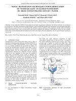
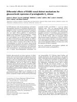
NOVEL ACTUATION MECHANISMS
FOR MEMS MIRRORS
KOH KAH HOW
NATIONAL UNIVERSITY OF SINGAPORE
2013
NOVEL ACTUATION MECHANISMS
FOR MEMS MIRRORS
KOH KAH HOW
(B. Eng.(Hons.)), National University of Singapore
A THESIS SUBMITTED
FOR THE DEGREE OF DOCTOR OF
PHILOSOPHY
DEPARTMENT OF
ELECTRICAL AND COMPUTER ENGINEERING
NATIONAL UNIVERSITY OF SINGAPORE
2013
i
Declaration
I hereby declare that the thesis is my original work and it has been
written by me in its entirety.
I have duly acknowledged all the sources of information which
have been used in the thesis.
This thesis has also not been submitted for any degree in any
university previously.
Koh Kah How
14
th
January 2013
ii
Acknowledgements
First and foremost, I would like to take this opportunity to express my
sincere gratitude to my graduate advisor, Associate Professor Vincent Lee
Chengkuo for his invaluable guidance and encouragement throughout my
Ph.D. study. Without his help, I would not be able to overcome all the
difficulties alone and be here at this final stage of my candidature. I will never
forget the time he sacrificed on me and the personal advice he gave me. I
would also like to thank Dr. Takeshi Kobayashi, Soon Bo Woon, Wang Nan
and Qian You for their support and advice rendered regarding the fabrication
of my devices. Without their help, my designs can never be realized
successfully.
I would also like to express my deepest appreciation to Dr. Lap Chan,
Dr. Ng Chee Mang and Leong Kam Chew for their support and knowledge
sharing during the weekly presentation session at GlobalFoundries, Sinagpore.
Without this EDB-Globalfoundries scholarship opportunity, I would not have
gained this much of knowledge, both technical and non-technical, from the
interaction with them and the rest of the Special Group (SP) students. And not
forgetting my fellow group of batch-mates from SP13, whom I have spent fun
and memorable times with during our postgraduate studies over the past years.
To the past and current colleagues that I’ve met in CICFAR, Dr. Hsiao
Fu-Li, Dr. Lin Yu-sheng, Dr. Liu Huicong, Dr. Lou Liang, Li Bo, Zhang
Songsong, Pitchappa Prakash, Ho Chong Pei and many others, I‘m grateful
that our paths have crossed. Without the presence of these colleagues, my
iii
research life would be much tougher without their help, discussion and
laughter. In addition, I would also like to extend my appreciation to Mrs Ho
Chiow Mooi for her administrative help and logistics support for the purchase
and loan of equipment over the past years.
Finally yet importantly, I would like to express my deepest gratitude to
my parents, brother and fiancée, Katherine Kor, for being with me and
supporting me all these while. Their unconditional love is the most precious
gift in my life.
iv
Table of Content
Declaration i
Acknowledgements ii
Table of Content iv
Summary vii
List of Tables ix
List of Figures x
List of Symbols xix
Chapter 1 Introduction
1.1 Optical MEMS 1
1.2 Applications of MEMS mirror 2
1.2.1 Projection Display 2
1.2.2 Variable Optical Attenuator 4
1.3 Actuation Schemes 6
1.3.1 Electrothermal actuation 7
1.3.2 Electrostatic actuation 9
1.3.3 Piezoelectric actuation 11
1.3.4 Electromagnetic actuation 13
1.4 Actuation Mechanisms 14
1.4.1 MEMS Scanners 15
1.4.2 MEMS Variable Optical Attenuators 19
1.5 Objectives of Thesis 22
1.6 Thesis organization 23
Chapter 2 MEMS Scanners Driven by 1×10 PZT Beam Actuators
2.1 Introduction 25
2.2 Design and Modeling 26
2.3 Device Microfabrication 30
2.4 Experimental Setup 33
2.5 Results and Discussion 35
v
2.5.1 Bending mode operation 35
2.5.2 Torsional mode operation 38
2.5.3 Mixed mode operation 42
2.6 Summary 48
Chapter 3 A PZT Driven MEMS VOA Using Attenuation Mechanism
With Combination of Rotational and Translational Effects
3.1 Introduction 49
3.2 Design and Modeling 51
3.3 Device Microfabrication 57
3.4 Experimental Setup 58
3.5 Results and Discussion 61
3.5.1 Bending mode operation 61
3.5.2 Torsional mode operation 63
3.5.3 Mixed mode operation 67
3.6 Summary 69
Chapter 4 A MEMS Scanner Based on Dynamic Mixed Mode Excitation
of a S-shaped PZT Actuator
4.1 Introduction 71
4.2 Design & Modeling 72
4.3 Device Microfabrication 76
4.4 Results and Discussion 79
4.4.1 DC Response 79
4.4.2 AC Response 80
4.5 Performance comparison of current designs with existing piezoelectric
MEMS scanners 89
4.6 Summary 92
Chapter 5 A MEMS Scanner Using Hybrid Actuation Mechanisms With
Low Operating Voltage
5.1 Introduction 94
5.2 Design & Modeling 95
5.2.1 Electrothermal Actuation 96
vi
5.2.2 Electromagnetic Actuation 102
5.2.3 Modal Analysis 104
5.3 Device Microfabrication 105
5.4 Results & Discussion 110
5.4.1 Static characterization 111
5.4.2 Dynamic characterization 114
5.5 Performance comparison of current design with existing EM MEMS
scanners 119
5.6 Summary 121
Chapter 6 Study of a MEMS VOA Driven By Hybrid Electromagnetic
and Electrothermal Actuation Mechanisms
6.1 Introduction 123
6.2 Design and modeling 124
6.2.1 EM actuation and attenuation principle 125
6.2.2 ET actuation and attenuation principle 128
6.3 Experimental setup 129
6.4 Results and Discussion 134
6.4.1 Optomechanical performance for EM attenuation mechanism 135
6.4.2 Optomechanical performance for ET attenuation mechanism 139
6.4.3 Optomechanical performance for hybrid attenuation mechanism 144
6.5 Performance comparison of current designs with existing MEMS
VOAs 145
6.6 Summary 148
Chapter 7 Conclusion and Future Work
7.1 Conclusion 150
7.2 Future Work 154
REFERENCES 157
APPENDIX 167
A. List of Awards 167
B. List of Publications 167
vii
Summary
Recent developments in the rapidly emerging discipline of micro-
electro-mechanical systems (MEMS) have shown special promise in sensors,
actuators, and micro-optical systems. In fact, optics is an ideal application
domain for MEMS technology as photons have no mass and are easier to be
actuated compared with other microscale objects. In conjunction with properly
designed mirrors, lenses and gratings, various micro-optical systems driven by
microactuators can be made to perform many different functions of light
manipulations such as reflection, beam steering, filtering, and collimating, etc.
In this thesis, various MEMS mirror designs for two-dimensional (2-D)
scanning and variable optical attenuator (VOA) applications are explored.
Four unique designs based on piezoelectric and hybrid actuation mechanisms
have been conceptualized. With the focus on the development of novel
actuation mechanisms to drive the MEMS mirrors, characterization of these
designs have been made from the perspective of the aforementioned
applications.
Two designs of piezoelectric driven MEMS scanners using mechanical
supporting beam integrated with 1×10 PZT actuators are designed, fabricated
and characterized. Through this design variation, the performances of these
PZT MEMS scanners are investigated by using different actuation
mechanisms to produce 2-D scanning patterns for both the devices. In the case
of VOA application, an attenuation range of 40 dB was achieved at 1V
dc
,
which is among the lowest operating voltage to be reported in the literature so
far for MEMS-based VOA.
viii
To further improve the scanning performance and reduce the number
of PZT actuators, a S-shaped actuator design was investigated. For the same ac
driving voltage, the optical deflection angle achieved by this S-shaped actuator
design is demonstrated to be larger than that of the 1×10 PZT actuator design.
2-D scanning images were also successfully demonstrated by superimposing
two ac signals into one signal to be used to excite the PZT actuator and drive
MEMS mirror.
Besides piezoelectric driven MEMS mirror, hybrid driven CMOS
compatible MEMS mirror based on electrothermal and electromagnetic
actuation mechanisms are also examined for 2-D scanning and VOA
applications. Various Lissajous scanning patterns were demonstrated at low
power condition, making the proposed hybrid actuation design approach
suitable for mobile 2-D raster scanning applications powered by batteries with
limited capacity. For the case of VOA application, three types of attenuation
mechanisms based on electromagnetic, electrothermal and hybrid actuations
were explored and studied. This unique design of using both electrothermal
and electromagnetic actuators simultaneously to achieve attenuation is the first
demonstration of such hybrid driven CMOS compatible MEMS VOA device.
ix
List of Tables
Table 1-1. Piezoelectric coefficient of selected piezoelectric materials [64]. 13
Table 2-1. Dimensions of the MEMS scanners for both designs. 28
Table 2-2 Comparison of designs A and B 47
Table 4-1. Dimensions of MEMS scanner driven by S-shaped PZT actuator.
74
Table 4-2. Comparison of FOM for different PZT MEMS scanner designs. 90
Table 5-1. Thermo-mechanical properties of materials used for ET actuator
simulation and modal analysis in ANSYS. 101
Table 5-2. Structural parameters of the fabricated MEMS scanner shown in
Fig. 5-10 109
Table 5-3. Comparison of FOM for different EM scanner designs. 120
Table 6-1. Detailed dimension of the microstructures for the hybrid MEMS
VOA device. 130
Table 6-2. Comparison of the optomechanical performance for EM and ET
attenuation 143
Table 6-3. Comparison of FOM for different MEMS VOA designs 146
x
List of Figures
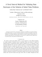
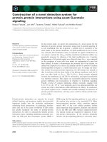
Fig. 1-1. Schematic illustration of the (a) DMD, consisting of micromirrors,
springs, hinges, yokes and CMOS substrate [21, 22], and (b)
GLV, where the color of each pixel is determined by the relative
position of the three movable and fixed ribbons [23, 24]. 4
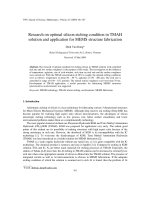
Fig. 1-2. (a) A SHOWWX+ laser picoprojector developed by Microvision
Inc. in 2010, projecting a presentation from a media player onto a
wall [26]. (b) A DLP-based picoprojector being integrated into a
commercial smartphone, Samsung Galaxy Beam GT-I8530. [25].
4
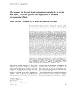
Fig. 1-3. Schematic diagram illustrating the various optical components in a
DWDM-based optical communication network. 6
Fig. 1-4. Schematic diagram of (a) out-of-plane bimorph actuator showing
its displacement in response to Joule heating when biased [34], (b)
in-plane U-shaped actuator design, which deploys hot-cold arms
of different widths [37], and (c) in-plane V-shaped chevron beam
actuator which buckles in the direction of tip when a current flows
through it [42]. 8
Fig. 1-5. Schematic diagram illustrating the various types of electrostatic
actuators commonly adopted in literature. They are (a) out-of-
plane parallel plate actuator [45], (b) in-plane rotary combs [49],
(c) out-of-plane staggered vertical combs [59], and (d) out-of-
plane angular vertical combs [59]. 10
Fig. 1-6. Schematic diagram illustrating the change in perovskite crystal
structure (a) before, and (b) after voltage is applied across it. 11
Fig. 1-7. (a) A SEM photo showing the electroplated gold electromagnetic
coils on the mirror plate and actuated by ac current at resonance in
the presence of permanent magnet [76]. (b) A schematic diagram
illustrating a permanent magnetic film integrated on the mirror
plate and actuated by the surrounding ac magnetic field [79]. 14
Fig. 1-8. SEM photos of MEMS scanners based on gimbaled, two frame
designs driven by (a) electromagnetic [81], (b) staggered vertical
electrostatic comb actuators [55], (c)-(e) piezoelectric PZT
actuators [69, 89, 96], and (f)-(g) gimbal-less designs driven by
folded dual S-shaped electrothermal bimorph [92] and
piezoelectric unimorph actuator [95], respectively. (h) Optical
microscope photo of a piezoelectric MEMS scanner for high
resolution 1-D scanning [71]. 17
Fig. 1-9. Photos of simple 2-D MEMS mirror designs driven by (a) a L-
shaped thermal bimorph cantilever actuator [97], and (b) external
coil exciting a mirror plate electroplated with permalloy [98]. 18
xi
Fig. 1-10. Schematic diagrams illustrating the attenuation principle for
various types of MEMS VOAs designs such as (a) shutter type
[101], (b) planar reflective type [102], and (c) 3-D reflective type
[103]. 19
Fig. 2-1. Schematic diagram of the MEMS scanners driven by 1×10 PZT
beam actuators for (a) design A, and (b) design B, respectively. In
design A, the electrical connections of the PZT beam actuators are
connected in series, i.e., the top electrode of one PZT actuator is
electrically connected to the bottom electrode of the adjacent
actuator. In design B, the electrical connections of the ten PZT
actuators are separated. The inset shows an illustration of torsional
mode, where the mirror twists about the y-axis. 27
Fig. 2-2. Equivalent circuit of the 1×10 PZT beam actuators labelled 1-10,
and their corresponding bond pads for (a) design A, and (b) design
B, respectively. 27
Fig. 2-3. Modal analysis of the MEMS scanner using finite element
software ABAQUS. (a) 1st bending mode at 6Hz. (b) 2nd bending
mode at 33Hz. (c) 1st torsional mode at 121Hz. (d) 2nd torsional
mode at 204Hz. 30
Fig. 2-4. Microfabrication process flow for making the devices. 31
Fig. 2-5. Magnified photos showing the packaged MEMS scanners for (a)
design A, and (b) design B, respectively. 31
Fig. 2-6. Optical microscopes photos of (a) PZT actuators connected in
series for design A, where the top electrode of a PZT actuator is
connected to the bottom electrode of the adjacent actuator, (b)
bond pads connected to the bottom electrodes of their respective
actuators for design A, (c) PZT actuators that are electrically
isolated from one another for design B, (d) bond pads connected
to either the top or bottom electrode of the actuators for design B,
(e) PZT actuators fabricated in parallel on top of a Si cantilever,
and (f) Si mirror surface. 33
Fig. 2-7. Schematic drawing of the experimental setup for measuring the
mirror deflection angle when the MEMS scanners are driven
under ac actuation voltages. 34
Fig. 2-8. Biasing configuration during bending mode operation for (a)
design A, where an ac voltage of, for example, 10V
pp
, was applied
to the ten serially connected PZT actuators, and (b) design B,
where an ac voltage of, for example, 10V
pp
, was applied to the ten
PZT actuators individually. 35
Fig. 2-9. Frequency response during bending mode operation for (a) Design
A, where 10V
pp
was applied to the ten serially connected PZT
actuators, and (b) Design B, where 5V
pp
was applied
simultaneously to all the ten actuators individually. The inset
xii
shows an example of a horizontal scanning trajectory obtained for
design A. 36
Fig. 2-10. AC response during bending mode operation for designs A and B.
In design A, ac voltages at 34 Hz were applied to the ten PZT
actuators, while in design B, ac voltages at 30 Hz were applied to
the ten PZT actuators individually. 36
Fig. 2-11. Biasing configuration during torsional mode operation for (a)
design A, where an ac voltage of, for example, 10V
pp
, was applied
to the ten serially connected PZT actuators, and (b) design B,
where an ac voltage of, for example, 10V
pp
, was applied to PZT
actuators 1 and 10, while the rest of the actuators were biased at
gradually lower V
pp
values. For actuators 1-5, the biases were
applied to the bottom electrodes, while the top electrodes were
grounded. In the case of actuators 6-10, the biases were applied to
the top electrodes, while the bottom electrodes were grounded. (c)
Schematic diagram showing the implementation of the potential
divider circuit for design B, where the ac output of the function
generator is split into five equal electric potentials. 39
Fig. 2-12. Frequency response during torsional mode operation for (a)
Design A, where 10V
pp
was applied to the ten serially connected
PZT actuators, and (b) Design B, where 5V
pp
was applied to the
first and tenth actuator. The inset shows an example of a vertical
scanning trajectory obtained for design A obtained. 41
Fig. 2-13. AC response during torsional mode operation for designs A and
B. In design A, ac voltages at 198 Hz were applied to the ten PZT
actuators, while in design B, ac voltages of different values at 89
Hz were applied to the PZT actuators. 41
Fig. 2-14. Biasing configuration during mixed mode operation for (a) design
A, where an ac voltage of, for example, 3V
pp
, at 34 Hz was
applied to the PZT actuators 1-5 for bending mode, while 3V
pp
, at
198 Hz, was applied to the PZT actuators 6-10 for torsional
mode, and (b) design B, where an ac voltage of, for example,
3V
pp
, at 89 Hz was applied to PZT actuators 1-3 and 8-10 for
torsional mode, while 3V
pp
, at 30 Hz was applied to the PZT
actuators 4-7 for bending mode. For actuators 1-3, the biases were
applied to the bottom electrodes, while the top electrodes were
grounded. In the case of actuators 8-10, the biases were applied to
the top electrodes, while the bottom electrodes were grounded. (c)
Schematic diagram showing the external electrical circuit required
for mixed mode operation for design B. 43
Fig. 2-15. AC response during mixed mode operation for (a) design A and,
(b) design B. 45
Fig. 2-16. Lissajous scan patterns obtained during mixed mode operation for
(a) design A and, (b) design B 46
xiii
Fig. 3-1. Schematic drawing of the piezoelectric MEMS VOA with dual
core collimator arranged in a 3-D configuration such that the light
beam focuses on the far edge center of the mirror plate. Bending
mode occurs when all the ten actuators are biased simultaneously
at same voltage. Torsional mode occurs where a set of five
actuators bends in one direction while the other set of five
actuators bends in the opposite direction. 51
Fig. 3-2. Schematic diagram illustrating the side profile of the dc-biased
PZT actuator during bend mode operation, with experimental
vertical displacement of δ
actuator
, mechanical rotation angle of
θ
B,mirror
and radius of curvature, r. 52
Fig. 3-3 Schematic diagrams showing the attenuation mechanism for
bending mode: (a) configuration refers to the initial state of
insertion loss. All of the laser beam from the input fiber is coupled
back into output fiber when the actuators are not biased, i.e.,
mirror surface remains normal to laser beam; (b) a portion of the
laser beam from input fiber deviates from the optimized reflection
light path when the actuators are biased, i.e., mirror undergoes
rotational and translational motion (c) mirror is rotated by an
angle, θ
B
,mirror, and the laser beam is displaced by a distance,
δ
B,laser
. 54
Fig. 3-4. Schematic diagrams showing attenuation mechanism for torsional
mode: (a) all of the light beam from the input fiber is coupled
back into output fiber when the actuators are not biased. It is the
initial state of insertion loss; (b) configuration refers to the
attenuation state where a portion of the laser beam from input
fiber is not coupled back to the output fiber due to that actuators
1-5 and actuators 6-10 being oppositely biased, i.e. mirror
undergoes rotational motion (c) mirror is rotated by an angle,
θ
T,mirror
, and the laser beam is displaced by a distance, δ
T,laser
. 54
Fig. 3-5. Close-up photo showing the packaged PZT MEMS VOA with a
gold-coated surface. 57
Fig. 3-6. Measured average displacement of fixed-free actuator tips versus
dc driving voltage applied to the top electrodes of all ten actuators.
58
Fig. 3-7. Schematic drawing of the measurement setup for 3-D MEMS
VOA characterization carried out on an anti-vibration optical
bench. The stage is capable of moving in X-Y-Z directions and
tilting along X-Y(θz) and Y-Z(θx) planes as well. 60
Fig. 3-8. Experimental data for bending mode. (a) Measured attenuation
curve versus dc voltage applied simultaneously to the top
electrodes of the ten actuators while the bottom electrodes are
grounded. (b) Bottom right (red) curve shows measured average
displacement of actuator tip, δ
actuator
, versus dc voltage applied
xiv
simultaneously to the top electrodes of ten actuators. Top left
(blue) curve shows the displacement of laser beam, δ
B,laser
, versus
dc voltage. The displacement of laser beam, δ
B,laser
, is calculated
using equations (3.5)-(3.7) and the values of δ
actuator
obtained from
the red curve
.
62
Fig. 3-9. Schematic drawing illustrating the electrical connections of the
top and bottom electrodes of each actuator to the dc power supply
in (a) bias case A, and (b) bias case B. (c) A look-up table
showing the individual dc bias driving each actuator under bias
case A and B for a given dc power supply voltage. 64
Fig. 3-10. Experimental data for torsional mode. (a) Measured attenuation
curves versus dc driving voltage of the power supply for both bias
cases A and B. (b) Top left (red) curve shows measured average
displacement of mirror edges, δ
mirror
, versus dc driving voltage of
power supply. Bottom right (blue) curve shows the displacement
of laser beam, δ
T,laser
, versus dc voltage of power supply. Both
curves were obtained using bias case A. The displacement of laser
beam, δ
T,laser
, is calculated using equations (3.8)-(3.10) and the
values of δ
mirror
obtained from the red curve
.
66
Fig. 3-11. Measured attenuation value as a function of dc bias applied to the
2 sets of actuators 1-5 and 6-10. 68
Fig. 4-1. (a) Schematic drawing of the MEMS scanner actuated by single S-
shaped PZT actuator. Bending and torsional modes occur when
the device is excited at the respective resonant frequencies. (b)
Top view of the MEMS scanner and the respective dimensions of
the structures. 73
Fig. 4-2. Finite element modal analysis for the two different mirror designs
using finite element simulation software ABAQUS. The 1
st
design
being simulated is a micromirror driven by a S-shaped actuator
design during (a) bending mode operation, where eigenfrequency
at 34.9 Hz and a maximum normalized Z-displacement of 1 was
obtained, and (b) torsional mode operation, where eigenfrequency
of 72.1 Hz and a maximum normalized Z-displacement of 0.9 was
obtained. The 2
nd
design being simulated is a micromirror driven
by straight cantilever actuator design during (c) bending mode
operation, where eigenfrequency of 35.3 Hz and a maximum
normalized Z-displacement of 1 was obtained, and (d) torsional
mode operation, where eigenfrequency of 128 Hz and a maximum
normalized Z-displacement of 0.36 was obtained. 74
Fig. 4-3. Microfabrication process flow for making the S-shaped PZT
actuator and the micromirror. 77
Fig. 4-4. Close-up photo showing the packaged MEMS mirror on a dual in-
line package (DIP). The bond wires connect the bond pads on the
device to the external pins of the DIP. 78
xv
Fig. 4-5. Optical microscope images of (a) S-shaped PZT actuator with a
portion of the mirror plate, and (b) two bond pads and their
respective bond wires to the DIP. 79
Fig. 4-6. Measured ODA versus DC voltage applied to S-shaped PZT
actuator. 80
Fig. 4-7. Frequency response showing a semi-log plot of measured ODA
versus excitation frequency at 0.5 V
pp
for both bending and
torsional modes. 81
Fig. 4-8. AC response for bending and torsional modes where the MEMS
scanner was excited independently with ac signals of 27 Hz and
70 Hz, respectively. 81
Fig. 4-9. Schematic diagram illustrating the biasing circuit required to
produce 2-D scanning pattern. Two sinusoidal waveforms of
different frequencies were inputted into a summing amplifier. V
B
and V
T
denote the peak-to-peak voltage for the ac excitation
signals with frequencies 27 Hz and 70 Hz, respectively. 83
Fig. 4-10. Waveform obtained from different voltage output. (a) Dotted (red)
and solid (blue) curves show the respective output of the 2
function generators when both V
B
and V
T
were at 0.5 V
pp
. (b)
Dotted (red) curve shows the resultant output from the summing
amplifier V
out
when V
B
and V
T
are 0.5V
pp
. 84
Fig. 4-11. Screenshot capture of the waveforms obtained from a oscilloscope
connected to the V
out
terminal, with various voltage bias
combinations such as (a) V
B
= 1V
pp
, V
T
= 0V
pp
, (b) V
B
= 0.8V
pp
,
V
T
= 0.3V
pp
, (c) V
B
= 0.5V
pp
, V
T
= 0.5V
pp
, and (d) V
B
= 0.3V
pp
,
V
T
= 1V
pp.
87
Fig. 4-12. 2-D Lissajous scanning patterns obtained when various
combinations of sinusoidal V
B
and V
T
were supplied by the two
function generators and superimposed by the summing amplifier,
where (a) V
B
= 3V
pp
, V
T
= 0V
pp
, (b) V
B
= 1V
pp
, V
T
= 0V
pp
, (c)V
B
= 0.8V
pp
, V
T
= 0.3V
pp
, (d) V
B
= 0.5V
pp
, V
T
= 0.5V
pp
, and (e) V
B
=
0.3V
pp
, V
T
= 1V
pp
. The experimental setup of the scanning line
obtained in (a) were slightly different from those obtained in (b)-
(e) so that the entire scanning line can be accommodated onto the
ruler scale. 88
Fig. 5-1. Schematic diagram of the proposed MEMS scanner incorporated
with hybrid actuation mechanisms. The vertical and horizontal
scanning motions are driven by ET and EM actuation
mechanisms, respectively. 96
Fig. 5-2. Schematic diagram illustrating the (a) proposed ET bimorph
actuator made of Al and Si, with the inset showing the winding
design of the Al metal layer and thin thermal insulating SiO
2
deposited around the windings; (b) working principle of ET
actuation and rotation about the vertical scanning axis i.e. x-axis
xvi
when ET actuators 1 & 2 are biased serially to give a mechanical
torque. 97
Fig. 5-3. Simulated plot illustrating the change in the tip displacement of a
single clamped ETl actuator for a unit temperature change. The
thickness of the Al metal layer is varied from 0.1µm to 6µm for
different Si device layer thickness of a SOI wafer. 99
Fig. 5-4. Plots of mechanical rotation angle and maximum temperature of
device versus total dc voltage applied to actuators 1 and 2.
Results are obtained from FEM simulation using ANSYS. 100
Fig. 5-5. Simulation result by ANSYS when ET actuators 3 and 4 are
biased with a total DC voltage of 10V. (a) Y-displacement profile
of the device where the mirror rotates about the x-axis. (b)
Temperature distribution profile of the device. 101
Fig. 5-6. Schematic drawing illustrating the working principle of EM
actuation and rotation about the horizontal scanning axis i.e. z-
axis when a mechanical torque, in the presence of external
magnetic field, is generated due to the current flow in the coil
embedded in the frame. (b) Top viewing drawing illustrating the
dimensions of the coils. Two turns of the EM coil are shown for
simplicity. 102
Fig. 5-7. Various mode shapes of the device derived from ANSYS
simulation. (a) 2
nd
eigenmode at 87.5 Hz for vertical scanning. (b)
3
rd
eigenmode at 160.3 Hz for horizontal scanning. (c) 6
th
eigenmode at 3014 Hz for horizontal scanning. 104
Fig. 5-8. Microfabrication process flow of the device 106
Fig. 5-9. Photos showing (a) an unpackaged 2-D MEMS scanner placed
beside a Singapore five-cent coin, (b) the device packaged in a
dual inline package, and (c) a close-up view showing the bond
pads connected to the pins of the package via gold bond wires. 108
Fig. 5-10. Optical micrographs showing the (a) C-shaped hinge connecting
the ETactuators to the frame, (b) T-shaped torsion bar, (c) Al EM
coils embedded in the frame, and (d) Al windings of the ET
actuator. 108
Fig. 5-11. Experimental setup for the optical characterization of device. Inset
shows the packaged device placed in between the magnets, with
red laser light impinging on the mirror surface 110
Fig. 5-12. I-V curves obtained for the EM coil, ET actuators 1 and 2
connected in series and ET actuators 3 and 4 connected in series.
Inset shows a detailed sweep of the coil within the 1V
dc
range,
obeying a linear fit of I(mA) = 1.8V (V). 111
Fig. 5-13. DC response for (a) ET actuation, and (b) EM actuation. 113
Fig. 5-14. Bode plots illustrating the frequency response for (a) ET actuation
where actuators 1 and 2 are biased in series, and (b) EM actuation.
114
xvii
Fig. 5-15. AC response for (a) ET actuation at 74Hz for two different cases
of biasing configurations; (b) EM actuation at 202Hz, with inset
showing an example of a horizontal scanning trajectory line
produced during EM actuation. 116
Fig. 5-16. Various Lissajous patterns generated from different combinations
of ET and EM biasing configurations. ET actuators 1 and 2 at 2
V
dc
and 2 V
ac
, 74 Hz are responsible for the horizontal scanning in
all 3 patterns while the biasing conditions for the vertical scanning
are (a) 0.1 V
ac
or 0.126 mA, 202 Hz; (b) 0.2 V
ac
or 0.252 mA ,
202Hz; (c) 2 V
ac
or 2.5 mA, 2926 Hz respectively. 118
Fig. 5-17. Performance comparison of the various EM MEMS scanners
reported in literature. 120
Fig. 6-1. Schematic diagram of the hybrid actuated MEMS VOA with dual-
fiber collimator arranged in 3-D free space configuration such that
the light beam focuses on the center of the aluminum mirror
surface. Insets A and B show the top view drawings illustrating
the dimensions and layout of the EM coils and ET windings,
respectively. The number of EM coils and ET windings have been
reduced for simplicity purposes. 125
Fig. 6-2. Schematic diagrams showing the (a) EM actuation mechanism in
the presence of an external permanent magnetic field and current
flowing in the coils embedded in the frame, and (b) EM
attenuation principle, where the laser beam is rotated and
displaced by an angle θ
EM
and distance δ
EM,laser
, respectively. 125
Fig. 6-3. Schematic diagram showing the (a) ET actuation mechanism
where ET actuators 1 and 2 are biased and heated up, and (b) ET
attenuation principle, where the laser beam is rotated and
displaced by an angle θ
ET
and distance δ
ET,laser
, respectively. 128
Fig. 6-4. A magnified photo showing the packaged MEMS VOA device.
Insets A and B show the optical micrographs of the ET windings
and EM coils respectively. Inset C shows a SEM micrograph of
the ET actuator, C-shaped joint, frame, T-shaped torsion bar and
mirror. 130
Fig. 6-5. (a) Schematic diagram of the measurement setup carried out on an
anti-vibration optical bench. The stages are capable of moving in
X-Y-Z directions and tilting along X-Y (θz) and Y-Z (θx) planes
as well. (b) Photo illustrating the actual measurement setup which
includes the tunable laser, power meter, two dc power supplies
and stages. (c) A magnified photo at the DUT region, where the
DUT is mounted upright in the presence of an external permanent
magnetic field. The dual fiber collimator is adjusted to a working
distance of 1mm away from the mirror surface. 131
Fig. 6-6. White light interferometer measurement of the surface roughness
for the aluminium coated mirror. 131
xviii
Fig. 6-7. Measured I-V curves for the EM coils and ET actuators,
respectively. 134
Fig. 6-8. (a) Experimental optical deflection angle and analytically
calculated laser spot displacement versus dc voltage applied to the
EM coil. The inset shows a schematic diagram of the EM
attenuation mechanism, where the laser spot no longer couples
perfectly from the input fiber into the output fiber after EM
actuation. (b) Measured attenuation-bias curves for difference
current direction in the EM coils. 136
Fig. 6-9. Measured wavelength dependent loss at various attenuation states
for EM attenuation. 138
Fig. 6-10. Comparison of mechanical rotation angle (θ) obtained from
simulation software ANSYS and optical rotation angle (2θ)
obtained from He/Ne red laser experiment. Inset shows the
simulated y-profile of the device obtained from ANSYS when ET
actuators 1 and 2 were biased serially at 3V
dc
. 139
Fig. 6-11. Analytically calculated and experimental data obtained for ET
attenuation mechanism. (a) Derived IR laser spot displacement
versus dc driving voltage applied serially to ET actuators 1 and 2.
The inset shows a schematic diagram of the ET attenuation
mechanism, where the laser spot no longer couples perfectly from
the input fiber into the output fiber after ET actuation. (b)
Measured attenuation-bias curves for different sets of ET
actuators. 140
Fig. 6-12. Measured wavelength dependent loss at various attenuation states
for ET attenuation. 142
Fig. 6-13. Measured attenuation value as a function of dc driving voltages
applied to EM and ET actuators during hybrid actuation. 144
Fig. 6-14. Performance comparison of various MEMS VOAs reported in
literature. 147
Fig. 7-1. Proposed system architecture to integrate proposed MEMS
scanner for display applications. 154
xix
List of Symbols
Symbol
Description
Unit
r Radius of curvature µm
D Working distance of dual core collimator mm
θ
B,mirror
Mechanical rotation angle of the mirror during
bending mode
°
θ
T,mirror
Mechanical rotation angle of the mirror during
torsional mode
°
L
mirror
Length of mirror plate mm
L
actuator
Length of actuator mm
δ
actuator
Vertical displacement of actuator
µm
δ
B,laser
Displacement of laser beam during bending
mode
µm
δ
T,laser
Displacement of laser beam during torsional
mode
µm
R
dot size
Radius of laser spot
µm
d
31
Piezoelectric constant
pm/V
S
Si
Compliance of silicon GPa
-1
S
PZT
Compliance of PZT
GPa
-1
t
Si
Thickness of silicon
µm
t
PZT
Thickness of PZT µm
E
Si
Young's Modulus of silicon
GPa
E
PZT
Young's Modulus of PZT GPa
α
Si
Coefficient of thermal expansion of silicon K
-1
α
PZT
Coefficient of thermal expansion of PZT
K
-1
w
Si
Width of silicon µm
wPZT
Width of PZT µm
ΔT
Difference in temperature
K
Chapter 1: Introduction
1
Chapter 1
Introduction
1.1 Optical MEMS
Micro-electro-mechanical systems (MEMS) technology has
demonstrated great promise in opening new frontiers in the applications of
sensors and actuators. Mechanical sensing and actuation mechanisms are now
integrated with electronics on a silicon substrate through the various micro-
fabrication technologies available today. This has brought forth rapid progress
in various industries such as telecommunication, biomedical and military
defense. Components fabricated with the emerging technologies of MEMS are
being incorporated rapidly into numerous applications. These MEMS
applications include inertial MEMS such as accelerometers and gyroscopes in
automobile and consumer electronics, thermoelectric and vibration-based
energy harvesters in implantable biomedical devices and wireless sensor nodes,
respectively.
In the optical MEMS regime, microstructures such as micromirrors,
microlens and gratings are driven to move or deform by actuators so that
unique functions such as light manipulation can be achieved. Cornerstones for
the success of optical MEMS technology include actuator technology, optics
design and development of movable or tunable micromechanical elements
such as rigid reflective mirror [1], deformable reflective mirror [2, 3], shutters
[4, 5], gratings [6], waveguides [7], and microlens [8, 9] . MEMS and optics
make a perfect match as MEMS devices have dimensions and actuation
Chapter 1: Introduction
2
distances comparable to the wavelength of light. In addition, optical MEMS
have long been a goal of forward-thinking electronics innovators, with big
companies such as IBM and Intel having reported significant successes in
using the traditional CMOS toolkit to micromachine optical interconnects and
structures [10, 11]. As these companies and other research laboratories around
the world pursue on a "computing with light" paradigm, the look for optical
MEMS to serve as connection between arithmetic-logic units on the same chip
will ensue in the near future.
1.2 Applications of MEMS mirror
With a number of advantage, including small size, light weight and fast
speed compared to conventional bulky scanners, optical MEMS mirrors have
been drawing attention for a wide range of applications such as displays [12,
13], optical communications [14-16], microspectroscopy [17] and optical
coherence tomography [18-20].
1.2.1 Projection Display
In the field of projection display application, the most successful
MEMS-based commercial product is probably the Digital Micromirror Device
(DMD), which utilize the Digital Light Processing (DLP) technology
developed proprietary by Texas Instrument in the early 1990s [21, 22]. As
shown in Fig. 1-1(a), the DMD consists of a semiconductor-based array of
fast, effective micron-meter size mechanical mirrors to redirect light from
LEDs or lasers into raster patterns that create visible displays. Each
micromirror corresponds to an image pixel and the pixel brightness can be
Chapter 1: Introduction
3
controlled by switching between two tilt states. First generation DMD device
with pixel pitch of 17µm, 0.7µm gap and ±10° rotation has given way to
10.8µm pitch, 0.7µm gap and ±12° rotation in their current latest 1080p
resolution product. Greater rotation can accommodate higher numerical
aperture, while smaller pixel pitch shrinks the chip area, offering cost benefit
to microdisplay and optical systems.
Besides using MEMS mirror which are reflective-type devices,
diffractive-type devices in the form of gratings have also been reported for
scanning purposes. In 1994, Solgaard et al. from Stanford University
developed the grating light valve (GLV), providing an alternative MEMS-
based technology for implementation in commercial projectors [23, 24]. The
key idea behind GLV technology is the use of movable ribbons to modulate
the phase of light so that it can be regarded as a MEMS tunable phase grating.
As shown in Fig. 1-1(b), each pixel consists of three movable and three fixed
ribbon strips, with each pair of movable and fixed ribbons being responsible
for the intensity of red, green or blue color. As such, the color of a pixel on the
screen is determined by the amount of red, blue and green light being
diffracted and incident collectively on the pixel as 1
st
order light.
In recent years, optical MEMS devices have also formed a circle of
growing interest, with the development of handheld picoprojectors based on
scanning mirror technology becoming an intriguing killer applications in
consumable electronics, IT and amusement business [12, 13]. Traditional
high-resolution mirror array approach developed for digital projector remains
too large to be adapted into a portable device. In order to display a much
Chapter 1: Introduction
4
bigger multimedia in the forms of images, movies or presentations on an
ordinary surface e.g. a wall or a table, MEMS-based scanner technology can
be incorporated into these portable gadgets that allow people to share these
multimedia much more easily and spontaneously [25, 26].
Fig. 1-1. Schematic illustration of the (a) DMD, consisting of micromirrors, springs, hinges,
yokes and CMOS substrate [21, 22], and (b) GLV, where the color of each pixel is determined
by the relative position of the three movable and fixed ribbons [23, 24].
Fig. 1-2. (a) A SHOWWX+ laser picoprojector developed by Microvision Inc. in 2010,
projecting a presentation from a media player onto a wall [26]. (b) A DLP-based picoprojector
being integrated into a commercial smartphone, Samsung Galaxy Beam GT-I8530. [25].
1.2.2 Variable Optical Attenuator
Besides projection display applications, optical MEMS have also been
an enabling tool for numerous cutting-edge devices in optical
communications. With the increasing demand for higher bandwidth and speed