Performance analysis of an endoreversible rectangular cycle with heat transfer loss and variable specific heats of working fluid
Bạn đang xem bản rút gọn của tài liệu. Xem và tải ngay bản đầy đủ của tài liệu tại đây (268.03 KB, 8 trang )
INTERNATIONAL JOURNAL OF
ENERGY AND ENVIRONMENT
Volume 6, Issue 1, 2015 pp.73-80
Journal homepage: www.IJEE.IEEFoundation.org
ISSN 2076-2895 (Print), ISSN 2076-2909 (Online) ©2015 International Energy & Environment Foundation. All rights reserved.
Performance analysis of an endoreversible rectangular cycle
with heat transfer loss and variable specific heats of
working fluid
Chao Wang
1,2,3
, Lingen Chen
1,2,3,
, Yanlin Ge
1,2,3
, Fengrui Sun
1,2,3
1
Institute of Thermal Science and Power Engineering, Naval University of Engineering, Wuhan 430033,
China.
2
Military Key Laboratory for Naval Ship Power Engineering, Naval University of Engineering, Wuhan
430033, China.
3
College of Power Engineering, Naval University of Engineering, Wuhan 430033, China.
Abstract
The performance of an air-standard rectangular cycle with heat transfer loss and variable specific heats of
working fluid is analyzed by using finite-time thermodynamics. The relations between the work output
and the compression ratio, between the efficiency and the compression ratio, and the optimal relation
between work output and the efficiency of the cycle are derived by detailed numerical examples.
Moreover, the effects of heat transfer loss and variable specific heats of working fluid on the cycle
performance are analyzed. The results show that the effects of heat transfer loss and variable specific
heats of working fluid on the cycle performance are obvious. The results may provide some guidelines
for the application of the rectangular cycle.
Copyright © 2015 International Energy and Environment Foundation - All rights reserved.
Keywords:
Finite-time thermodynamics; Endoreversible rectangular cycle; Working fluid with
variable specific heats; Performance analysis.
1. Introduction
The application of Finite-time Thermodynamics [1-7] in performance analysis and optimization of
thermal engine has achieved series of results. Rubin [8] defined the endoreversible cycle model earliest.
Mozurkewich et al. [9] and Hoffman et al. [10] derived the optimal motion of the piston by using finite
time thermodynamics and optimal control theory. Chen et al. [11] modeled the Diesel cycle with friction
loss and studied the effect of friction loss on cycle performance. Klein et al. [12] and Chen et al. [13, 14]
studied the performance of Diesel cycle and Otto cycle with heat transfer loss, and analyzed the effect of
heat transfer loss on the performance. Al-Hinti et al. [15] studied the performance of Diesel cycle by
using different heat transfer model. Qin et al. [16] and Ge et al. [17] derived the performance
characteristics of Diesel cycle with friction loss and heat transfer loss. The works mentioned above were
performed without considering the variable specific heats of the working fluid. Ghatak and Chakraborty
[18] analyzed the performance of Dual cycle by considering the effect of heat transfer loss and variable
specific heats of working fluid. Chen et al. [19] studied the performance characteristics of an irreversible
Dual cycle with friction loss and linear variable specific heats of working fluid. Ge et al. [20-22] studied
the performance of endoreversible and irreversible Otto cycle and Diesel cycle with variable specific
International Journal of Energy and Environment (IJEE), Volume 6, Issue 1, 2015, pp.73-80
ISSN 2076-2895 (Print), ISSN 2076-2909 (Online) ©2015 International Energy & Environment Foundation. All rights reserved.
74
heats of the working fluid. Chen et al. [23] modeled a class of universal heat engine cycle with friction
loss and heat transfer loss by considering the effect of variable specific heats of working fluid.
Rectangular cycle consists of four processes: an isochoric and an isobaric heat addition process, an
isochoric and an isobaric heat rejection process. Ferreira Da Silva [24] derived the power output and the
efficiency of rectangular cycle by using classical thermodynamics. Liu et al. [25] modeled endoreversible
rectangular cycle with heat transfer loss and studied the performance characteristics of the cycle. Liu et
al. [26] modeled irreversible rectangular cycle with friction loss and heat transfer loss by using finite
time thermodynamics, and analyzed the effect of friction loss and heat transfer loss on cycle
performance. Based on Refs. [24-26], this paper will study the performance characteristics of
endoreversible rectangular cycle with heat transfer loss and variable specific heats of working fluid.
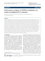
2. Cycle model
An air standard rectangular cycle is shown in Figure 1. The heat additions are an isochoric process 1-2
and an isobaric process 2-3; the heat rejections are an isochoric process 3-4 and an isobaric process 4-1.
(a) P-V diagram of the cycle model (b) T-S diagram of the cycle model
Figure 1. Endoreversible rectangular cycle model
The specific heats of working fluid are variable in practical cycle, and the performance of the cycle is
affected greatly by the variation. According to Refs. [20, 24], it can be supposed that the specific heats of
the working fluid are only related to its temperature, and over the temperature ranges generally
encountered for gases in heat engines (300-2200K), the specific heats show a linear relationship with the
temperature, which may be closely approximated in the following forms:
C
pm p
akT=+
(1)
vm
C
v
bkT=+
(2)
where
p
a ,
v
b and k are constants. According to the relation between
pm
C and
vm
C
p
mvmpv
RC C a b=−=−
(3)
where
R
is the molar gas constant of the working fluid.
The heat added to unit mass of working fluid per cycle may be written as
3
2
12
1 2 12 23
22 22
21 2 1 32 3 2
22
21 32 3 1
()0.5( )()0.5( )
()()0.5( )
T
T
in in in vm pm
TT
vp
vp
QQQ QQ CdTCdT
bTT kTT aTT kTT
bT T aT T kT T
=+=+= +
=−+ −+−+ −
=−+−+ −
∫∫
(4)
International Journal of Energy and Environment (IJEE), Volume 6, Issue 1, 2015, pp.73-80
ISSN 2076-2895 (Print), ISSN 2076-2909 (Online) ©2015 International Energy & Environment Foundation. All rights reserved.
75
The heat rejected from unit mass of working fluid per cycle may be written as
3
4
41
1 2 34 41
22 22
34 3 4 41 4 1
22
34 41 3 1
()0.5( )()0.5( )
()()0.5( )
T
T
out out out vm pm
TT
vp
vp
QQQ QQ CdTCdT
bTT kTT aTT kTT
bT T a T T kT T
=+=+= +
=−+ −+ −+ −
=−+ −+ −
∫∫
(5)
The work output of the cycle is
2431 3124
3124 312 4
()()
()( )( )
in out v p
pv
WQ Q bTTTT aTTTT
abTTTT RTTTT
=− = +−−+ +−−
= − +−− = +−−
(6)
According to the ideal gas equation
pV nRT= , one has
32 32
//VV TT=
(7)
41 41
//VV TT=
(8)
The compression ratio is defined as
32
/VV
γ
= , therefore
32
TT
γ
=
(9)
41
TT
γ
=
(10)
22 2
v2 1 2 2 1
() (1)0.5( )
in p
QbTTaT kTT
γγ
=−+ −+ −
(11)
22 2
v2 1 1 2 1
()(1)0.5( )
out p
QbTTaT kTT
γγγ
=−+−+ −
(12)
21
(1)( )WR TT
γ
=− −
(13)
There are no losses in an ideal rectangular cycle, but the heat transfer loss can not be ignored in an
endoreversible rectangular cycle. One can assume that the heat transfer loss through the cylinder wall is
proportional to the temperature difference between the working fluid and the atmosphere, and that the
wall temperature is a constant at
0
T . One has the heat added to unit mass of working fluid by combustion
as the following relation [14-16].
13 21
() ( )
in
QTT TT
α
βαβγ
=− + =− +
(14)
where
α
and
β
are two constants related to the combustion and heat transfer.
The efficiency of the cycle is
21
22 2
21 2 2 1
(1)( )
()(1)0.5( )
in
vp
RTT
W
QbTTaT kTT
γ
η
γγ
−−
==
−+ −+ −
(15)
When
γ
and
1
T are given,
2
T can be obtained from Eq. (11) and Eq. (14).
22 2
11 1
2
2
[ + ( 1)+ ]+ [ + ( 1)+ ] +2 ( +0.5 +
=
vp vp v
ba ba k bT kT T
T
k
γβγ γβγγ αβ
γ
−− − −)
(16)
Defining
International Journal of Energy and Environment (IJEE), Volume 6, Issue 1, 2015, pp.73-80
ISSN 2076-2895 (Print), ISSN 2076-2909 (Online) ©2015 International Energy & Environment Foundation. All rights reserved.
76
=+( 1)+
vp
Ab a
γβγ
−
(17)
2
11 1
=+0.5+
v
BbT kT T
αβ
−
(18)
The work output and the efficiency of the cycle are as follows:
22
1
2
++2
(1)( )
AAkB
WR T
k
γ
γ
γ
−
=− −
(19)
22
22 22 22 2 222
11
(1)( +2 )
[ ( 1)]( +2 ) + +2 0.5
vp v
RAkBA
ba AkBAAkBAAkBbkT kT
γγ
η
γγ γ γγγ
−−
=
+− −+ − − −
(20)
3. Numerical examples and discussion
According to Refs. [14, 20], ranges of parameters are as follows:
1. 0 1 0. 0
γ
=
− ,
60000 70000 /
J
mol
α
=−
,
20 30 /
J
mol K
β
=− ⋅,
2
0.003844 0.009844 /kJmolK=− ⋅, 19.868 23.868 /
v
bJmolK
=
−⋅,
1
300 400TK=− .
Using the above ranges of parameters, the characteristics curves of
W
γ
−
,
ηγ
−
, and W
η
− are plotted
as in Figures 2-14.
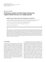
Figures 2-13 show the effects of different parameters on cycle performance when
1
=300TK. One can see
that the work output versus compression ratio characteristics and the efficiency versus compression ratio
characteristics are parabolic curves, and the work output versus efficiency is loop shaped.
1 1.5 2 2.5 3 3.5 4 4.5
0
500
1000
1500
2000
2500
3000
3500
=25 /
J
mol K
β
⋅
/( / )WJmol
=19.868 /
v
bJmolK
⋅
2
=0.005844 /kJmolK
⋅
=70000 /
J
mol
α
=65000 /
J
mol
α
=60000 /
J
mol
α
γ
1 1.5 2 2.5 3 3.5 4 4.5
0
0.02
0.04
0.06
0.08
0.1
0.12
=25 /
J
mol K
β
⋅
=19.868 /
v
bJmolK⋅
2
=0.005844 /kJmolK
⋅
=70000 /
J
mol
α
=65000 /
J
mol
α
=60000 /
J
mol
α
γ
η
Figure 2. The influence of
α
on cycle work output
Figure 3. The influence of
α
on cycle efficiency
0 0.02 0.04 0.06 0.08 0.1
0
500
1000
1500
2000
2500
3000
3500
/( / )WJmol
η
=25 /
J
mol K
β
⋅
=19.868 /
v
bJmolK⋅
2
=0.005844 /kJmolK⋅
=70000 /
J
mol
α
=65000 /
J
mol
α
=60000 /
J
mol
α
1 1.5 2 2.5 3 3.5 4 4.5
0
500
1000
1500
2000
2500
3000
3500
=65000 /
J
mol
α
=25 /
J
mol K
β
⋅
=19.868 /
v
bJmolK⋅
2
=0.005844 /kJmolK⋅
=30 /
J
mol K
β
⋅
=20 /
J
mol K
β
⋅
/( / )WJmol
γ
Figure 4. The influence of
α
on cycle work output
versus efficiency
Figure 5. The influence of
β
on cycle work output
International Journal of Energy and Environment (IJEE), Volume 6, Issue 1, 2015, pp.73-80
ISSN 2076-2895 (Print), ISSN 2076-2909 (Online) ©2015 International Energy & Environment Foundation. All rights reserved.
77
1 1.5 2 2.5 3 3.5 4 4.5
0
0.02
0.04
0.06
0.08
0.1
0.12
=65000 /
J
mol
α
=20 /
J
mol K
β
⋅
=30 /
J
mol K
β
⋅
=25 /
J
mol K
β
⋅
=19.868 /
v
bJmolK⋅
2
=0.005844 /kJmolK
⋅
γ
η
0 0.02 0.04 0.06 0.08 0.1
0
500
1000
1500
2000
2500
3000
3500
=65000 /
J
mol
α
=20 /
J
mol K
β
⋅
=30 /
J
mol K
β
⋅
=25 /
J
mol K
β
⋅
=19.868 /
v
bJmolK
⋅
2
=0.005844 /kJmolK
⋅
η
/( / )WJmol
Figure 6. The influence of
β
on cycle efficiency
Figure 7. The influence of
β
on cycle work output
versus efficiency
Figures 2-7 show the effects of combustion and heat transfer.
α
is a parameter related to the combustion
and it reflects the heating value of the fuel.
β
is a parameter related to heat transfer loss. In this case,
when
α
increases about 16.75%, the maximum work output increases about 32.73%, the efficiency at
maximum work output increases about 7.52%, the compression ratio at maximum work output increases
about 6.95%; the maximum efficiency increases about 7.51%, the work output at maximum efficiency
increases about 32.75%, the compression ratio at maximum efficiency increases about 7.10%. And when
β
decreases about 33.3%, the maximum work output increases about 53.37%, the efficiency at
maximum work output increases about 11.60%, the compression ratio at maximum work output
increases about 10.27%; the maximum efficiency increases about 11.47%, the work output at maximum
efficiency increases about 53.43%, the compression ratio at maximum efficiency increases about
10.50%.
Figures 8-10 show the effects of
p
a
and
v
b on cycle performance. From Eqs. (1) and (2), one can see that
when
=0k ,
pm p
Ca= and
vm v
Cb= ,
p
a and
v
b are constant specific heats of working fluid. Because
==
pm vm p v
RC C a bR=−=− constant,
p
a and
v
b must change synchronously. The results show that the
maximum work output and the maximum efficiency of the cycle will decrease with the increases of
p
a and
v
b , and the values of compression ratios at maximum work output point and maximum efficiency
point will decrease too. Furthermore, when
v
b increases about 20.13%, the maximum work output
decreases about 9.57%, the efficiency at maximum work output decreases about 14.26%, the
compression ratio at maximum work output decreases about 2.06%; the maximum efficiency decreases
about 14.24%, the work output at maximum efficiency decreases about 9.58%, the compression ratio at
maximum efficiency increases about 2.10%.
1 1.5 2 2.5 3 3.5 4
0
500
1000
1500
2000
2500
3000
3500
=65000 /
J
mol
α
=25 /
J
mol K
β
⋅
=19.868 /
v
bJmolK
⋅
2
=0.005844 /kJmolK⋅
=21.868 /
v
bJmolK
⋅
=23.868 /
v
bJmolK
⋅
/( / )WJmol
γ
1 1.5 2 2.5 3 3.5 4
0
0.02
0.04
0.06
0.08
0.1
0.12
=65000 /
J
mol
α
=25 /
J
mol K
β
⋅
=19.868 /
v
bJmolK⋅
2
=0.005844 /kJmolK
⋅
=21.868 /
v
bJmolK
⋅
=23.868 /
v
bJmolK
⋅
γ
η
Figure 8. The influence of
v
b on cycle work output
Figure 9. The influence of
v
b on cycle efficiency
International Journal of Energy and Environment (IJEE), Volume 6, Issue 1, 2015, pp.73-80
ISSN 2076-2895 (Print), ISSN 2076-2909 (Online) ©2015 International Energy & Environment Foundation. All rights reserved.
78
Figures11-13 show the effect of
k
on cycle performance. The degree of variation of specific heats with
temperature will be acute when
k increases. One can see that the maximum work output and the
maximum efficiency of the cycle will decrease with the increase of
k , and the values of compression
ratios at maximum work output point and maximum efficiency point will decrease too. Here, when
k
increases about 156%, the maximum work output decreases about 10.81%, the efficiency at maximum
work output decreases about 16.37%, the compression ratio at maximum work output decreases about
2.05%; the maximum efficiency decreases about 16.35%, the work output at maximum efficiency
decreases about 10.78%, the compression ratio at maximum efficiency decreases about 1.57%.
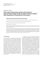
Figure 14 show the relationship between the work output and the efficiency of the cycle in different
initial temperature
1
T . One can see that the maximum work output and the maximum efficiency of the
cycle will decrease with the increase of
1
T . Furthermore, when
1
T increases about 33.33%, the maximum
work output decreases about 27.14%, the efficiency at maximum work output decreases about 19.04%,
the compression ratio at maximum work output decreases about 12.89%; the maximum efficiency
decreases about 19.12%, the work output at maximum efficiency decreases about 28.12%, and the
compression ratio at maximum efficiency decreases about 12.10%.
0 0.02 0.04 0.06 0.08 0.1
0
500
1000
1500
2000
2500
3000
3500
=65000 /
J
mol
α
=25 /
J
mol K
β
⋅
=19.868 /
v
bJmolK⋅
2
=0.005844 /kJmolK⋅
=21.868 /
v
bJmolK
⋅
=23.868 /
v
bJmolK⋅
/( / )WJmol
η
1 1.5 2 2.5 3 3.5 4
0
500
1000
1500
2000
2500
3000
3500
=65000 /
J
mol
α
=25 /
J
mol K
β
⋅
=19.868 /
v
bJmolK
⋅
2
=0.003844 /kJmolK⋅
2
=0.005844 /kJmolK⋅
2
=0.009844 /kJmolK⋅
/( / )WJmol
γ
Figure 10. The influence of
v
b on cycle work
output versus efficiency
Figure 11. The influence of
k
on cycle work
output
1 1.5 2 2.5 3 3.5 4
0
0.02
0.04
0.06
0.08
0.1
0.12
=65000 /
J
mol
α
=25 /
J
mol K
β
⋅
=19.868 /
v
bJmolK
⋅
2
=0.003844 /kJmolK
⋅
2
=0.005844 /kJmolK
⋅
2
=0.009844 /kJmolK
⋅
γ
η
0 0.02 0.04 0.06 0.08 0.1 0.12
0
500
1000
1500
2000
2500
3000
3500
=65000 /
J
mol
α
=25 /
J
mol K
β
⋅
=19.868 /
v
bJmolK
⋅
2
=0.003844 /kJmolK
⋅
2
=0.005844 /kJmolK
⋅
2
=0.009844 /kJmolK⋅
/( / )WJmol
η
Figure 12. The influence of k on cycle efficiency
Figure 13. The influence of k on cycle work
output versus efficiency
4. Conclusion
In this paper, an air-standard rectangular cycle with heat transfer loss and variable specific heats of
working fluid is analyzed by using finite-time thermodynamics. The analytical functions of the work
output and the efficiency are derived, and the performance characteristics of the cycle are obtained by
detailed numerical examples. The results show that the effects of heat transfer loss and variable specific
International Journal of Energy and Environment (IJEE), Volume 6, Issue 1, 2015, pp.73-80
ISSN 2076-2895 (Print), ISSN 2076-2909 (Online) ©2015 International Energy & Environment Foundation. All rights reserved.
79
heats of working fluid on the cycle performance are obvious. The results may provide some guidelines
for the application of the rectangular cycle.
0 0.02 0.04 0.06 0.08 0.1
0
500
1000
1500
2000
2500
3000
3500
/( / )WJmol
=65000 /
J
mol
α
=25 /
J
mol K
β
⋅
=19.868 /
v
bJmolK
⋅
2
=0.005844 /kJmolK
⋅
η
1
=300TK
1
=350TK
1
=400TK
Figure 14. The influence of
1
T on cycle work output versus efficiency
Acknowledgments
This paper is supported by the National Natural Science Foundation of P. R. China (Project No.
10905093).
Reference
[1] Curzon F L, Ahlborn B. Efficiency of a Carnot engine at maximum power output. Am. J. Phys.,
1975, 43(1): 22-24.
[2] Bejan A. Entropy generation minimization: The new thermodynamics of finite-size devices and
finite-time processes. J. Appl. Phys., 1996, 79(3): 1191-1218.
[3] Berry R S, Kazakov V A, Sieniutycz S, Szwast Z, Tsirlin A M. Thermodynamic Optimization of
Finite Time Processes. Chichester: Wiley, 1999.
[4] Chen L, Wu C, Sun F. Finite time thermodynamic optimization or entropy generation
minimization of energy systems. J. Non-Equilib. Thermodyn., 1999, 24(4): 327-359.
[5] Chen L, Sun F. Advances in Finite Time Thermodynamics: Analysis and Optimization. New
York: Nova Science Publishers, 2004.
[6] Chen L. Finite Time Thermodynamic Analysis of Irreversible Process and Cycles. Beijing: Higher
Education Press, 2005(in Chinese).
[7]
Andresen B. Current trends in finite-time thermodynamics. Angewandte Chemie
International Edition, 2011, 50(12) : 2690-2704.
[8] Rubin M H. Optimal configuration of a class of irreversible heat engines. Phys. Rev. A, 1979,
19(3): 1272-1287.
[9] Mozurkewich M, Berry R S. Optimal paths for thermodynamic systems: the ideal Otto cycle. J.
Appl. Phys., 1982, 53(1): 34-42.
[10] Hoffman K H, Watowich S J, Berry R S. Optimal paths for thermodynamic systems: The ideal
Diesel cycle. J Appl. Phys., 1982, 85(6): 2125-2134.
[11] Chen L, Lin J, Luo J, Sun F, Wu C. Friction effect on the characteristic performance of Diesel
cycles. Int. J. Energy Research, 2002, 26(11): 965-971.
[12] Klein S A. An explanation for observed compression ratios in internal combustion engines. Trans.
ASME J. Engng. Gas Turbine Pow. 1991, 113(4): 511-513.
[13] Chen L, Zen F, Sun F. Heat transfer effects on the net work output and power as function of
efficiency for air standard Diesel cycle. Energy, 1996, 21(12): 1201-1205.
[14] Chen L, Zen F, Sun F. Heat transfer effects on the net work output and efficiency characteristics
for an air standard Otto cycle. Energy Convers. Magmt. 1998, 39(7): 643-648.
[15] Al-Hinti I, Akash B, Abu-Nada E. Performance analysis of air-standard Diesel cycle using an
alternative irreversible heat transfer approach. Energy Convers. Manage, 2008, 43(15): 2019-2031.
[16] Qin X, Chen L, Sun F, Wu C. The universal power and efficiency characteristics for irreversible
reciprocating heat engine cycles. Eur. J. Phys., 2003, 24(4): 359-366.
International Journal of Energy and Environment (IJEE), Volume 6, Issue 1, 2015, pp.73-80
ISSN 2076-2895 (Print), ISSN 2076-2909 (Online) ©2015 International Energy & Environment Foundation. All rights reserved.
80
[17] Ge Y, Chen L, Sun F, Wu C. Reciprocating heat-engine cycles. Ap. Energy, 2005, 81(4): 397-408.
[18] Ghatak A, Chakraborty S. Effect of external irreversibilities and variable thermal properties of
working fluid on thermal performance of a Dual internal combustion engine cycle. Strojnicky
Casopsis (J. Meh. Energy), 2007, 58(1): 1-12.
[19] Chen L, Ge Y, Sun F, Wu C. Effects of heat transfer, friction and variable specific heats of
working fluid on performance of an irreversible Dual cycle. Energy Convers. Mgnt. 2006,
47(18/19):3224-3234.
[20] Ge Y, Chen L, Sun F, Wu C. Thermodynamic simulation of performance of an Otto cycle with
heat transfer and variable specific heats of working fluid. Int. J. Therm. Sci., 2005, 44(5):506-511.
[21] Ge Y, Chen L, Sun F, Wu C. The effects of variable specific heats of working fluid on the
performance of an irreversible Otto cycle. Int. J. Exergy, 2005, 2(3):274-283.
[22] Ge Y, Chen L, Sun F, Wu C. Performance of an endoreversible Diesel cycle with variable specific
heats of working fluid. Int. J. Ambient Energy, 2008, 29(3):127-136.
[23] Chen L, Ge Y, Sun F. Unified thermodynamic description and optimization for a class of
irreversible reciprocating heat engine cycles. Proc. IMechE, Part D: J. Automob. Eng., 2008,
222(D8): 1489-1500.
[24] Ferreira da Silva M F. Some considerations about thermodynamic cycles. Eur. J. Phys., 2012,
33(1): 13-42.
[25] Liu X, Chen L, Qin X, Ge Y, Sun F. Finite-time thermodynamic analysis for an endoreversible
rectangular cycle. Energy Conservation, 2013, 32(1): 19-21(in Chinese).
[26] Liu C, Chen L, Ge Y, Sun F. The power and efficiency characteristics for an irreversible
rectangular cycle. Power and Energy, 2013, 34(2): 113-117(in Chinese).
Chao Wang received her BS Degree in 2009 from Wuhan University. She is pursuing for her MS
Degree in power engineering and engineering thermophysics from Naval University of Engineering, P
R China. Her work covers topics in finite time thermodynamics and technology support for propulsion
plants. She is the author or coauthor of 4 peer-refereed articles.
Lingen Chen received all his degrees (BS, 1983; MS, 1986, PhD, 1998) in power engineering an
d
engineering thermophysics from the Naval University of Engineering, P R China. His work covers a
diversity of topics in engineering thermodynamics, constructal theory, turbomachinery, reliability
engineering, and technology support for propulsion plants. He had been the Director of the Department
of Nuclear Energy Science and Engineering, the Superintendent of the Postgraduate School, and the
President of the College of Naval Architecture and Power. Now, he is the Direct, Institute of Thermal
Science and Power Engineering, the Director, Military Key Laboratory for Naval Ship Powe
r
Engineering, and the President of the College of Power Engineering, Naval University of Engineering,
P R China. Professor Chen is the author or co-author of over 1410 peer-refereed articles (over 620 in
English journals) and nine books (two in English).
E-mail address: ; , Fax: 0086-27-83638709 Tel: 0086-27-83615046
Yanlin Ge received all his degrees (BS, 2002; MS, 2005, PhD, 2011) in power engineering an
d
engineering thermophysics from the Naval University of Engineering, P R China. His work covers
topics in finite time thermodynamics and technology support for propulsion plants. Dr Ge is the autho
r
or coauthor of over 90 peer-refereed articles (over 40 in English journals).
Fengrui Sun received his BS Degrees in 1958 in Power Engineering from the Harbing University o
f
Technology, P R China. His work covers a diversity of topics in engineering thermodynamics,
constructal theory, reliability engineering, and marine nuclear reactor engineering. He is a Professor in
the College of Power Engineering, Naval University of Engineering, P R China. Professor Sun is the
author or co-author of over 850 peer-refereed papers (over 440 in English) and two books (one in
English).