Adaptive interval type 2 fuzzy logic control of marine vessels
Bạn đang xem bản rút gọn của tài liệu. Xem và tải ngay bản đầy đủ của tài liệu tại đây (4.28 MB, 181 trang )
ADAPTIVE INTERVAL TYPE-2 FUZZY LOGIC
CONTROL OF MARINE VESSELS
XUETAO CHEN
NATIONAL UNIVERSITY OF SINGAPORE
2013
ADAPTIVE INTERVAL TYPE-2 FUZZY LOGIC
CONTROL OF MARINE VESSELS
XUETAO CHEN
(B.Eng, HIT )
A THESIS SUBMITTED
FOR THE DEGREE OF DOCTOR OF PHILOSOPHY
DEPARTMENT OF ELECTRICAL AND COMPUTER ENGINEERING
NATIONAL UNIVERSITY OF SINGAPORE
2013
Acknowledg ements
It is my great pleasure to thank all the people who enabled me to perform this work.
Firstly, I am extremely grateful to my supervisor, Assoc. Prof. Woei Wan Tan,
for her outstanding guidance and continuous support on my research and life during
my Ph.D study. Without her commitment and dedication, I would not have honed my
research skills and capabilities as well as I did in the past four years. The numerous
discussions with her throughout the course of this research have been most fulfilling
and have given me a deeper insight in fuzzy logic and control theory.
Jointly, I would like to thank Asso c. Prof. Woei Wan Tan, Asso c. Prof. Che
Sau Chang and Prof. Tien Fang Fwa for the opportunity to participate in the idea
conceptualization and grant pro posal writing at Center for Maritime Studies of NUS.
I salute them for their exemplary effort s in building relationships with bo th academia
and industry and dedication to the Maritime and Offshore industry. Special thanks
to Assoc. Prof. Stephane Bressan and Dr. Baljeet Singh Malhotra, I have learnt a
lot from discussions with them.
My appreciation goes to Prof. Qingguo Wang, Assoc. Prof. Cheng Xiang and
Asso c. Prof. Kok Kiong Tan in my thesis committee, for their kind advice and
guidance on my thesis.
I also wish to take this opportunity to thank professors in Department of Electrical
i
and Computer Engineering of NUS for building up my fundamentals in control theory.
My gratitude goes to Dr. Teck Wee Chua and Dr. Maowen Nie for their help and
technical troubleshooting during the initial phases and later comradeship. Sincere
thanks goes to many colleagues and friends in the Advanced Control Technology
Laboratory, Control and Simulations Labo r atory and Center for Maritime Studies,
with special mention of Dr. Yang Yang, D r. Lichun Shao, Dr. Han Yan, Mr. Xingguo
Shao, Dr. Huaping Dai, Dr. Xinhua Wang, Mr. Gangquan Dai, Mr. Chao Yu, Dr.
Keng Peng Tee, Mr. Xiangxu Dong , Ms. Xiaolian Zheng, Ms. Lingling Cao, Mr.
Yue Yang, Dr. Dong Yang, Dr. Zhuo Sun, Dr. Jianfeng Zheng and Dr. Hongtao Hu
for the lively discussions, sharing of ideas and happiness along the journey. Also my
sincere t hanks to all who have helped in one way or another in the completion of this
thesis.
Last but not least, I would like to express my gr atitude to my parents Liang Chen
and Guoxian Ding, my brother and sister in law Xuehui Chen and Yajing Tong, and
my girl friend Xue Wang f or their unquestioning love, trust and encouragement. They
have always been there for me, stood by me through the good times and the bad.
ii
Contents
Acknowledgements i
Summary vii
List of Figures xi
List of Tables xiv
1 Introduction 1
1.1 Marine Control Systems . . . . . . . . . . . . . . . . . . . . . . . . . 2
1.1.1 Autopilots . . . . . . . . . . . . . . . . . . . . . . . . . . . . . 3
1.1.2 Dynamic Positioning Systems . . . . . . . . . . . . . . . . . . 4
1.1.3 Tracking Control Systems . . . . . . . . . . . . . . . . . . . . 7
1.1.4 Basic Configuration . . . . . . . . . . . . . . . . . . . . . . . . 8
1.2 Interval Type-2 Fuzzy Logic . . . . . . . . . . . . . . . . . . . . . . . 12
1.3 Objectives and Scope of the Thesis . . . . . . . . . . . . . . . . . . . 14
1.4 Organization of the Thesis . . . . . . . . . . . . . . . . . . . . . . . . 17
2 Preliminaries and Design Tools 19
2.1 Modeling of Marine Vessels . . . . . . . . . . . . . . . . . . . . . . . . 19
iii
2.1.1 Kinematics . . . . . . . . . . . . . . . . . . . . . . . . . . . . 20
2.1.2 Dynamics . . . . . . . . . . . . . . . . . . . . . . . . . . . . . 22
2.1.3 Marine System Simulator . . . . . . . . . . . . . . . . . . . . 23
2.2 Type-1 Fuzzy Logic System . . . . . . . . . . . . . . . . . . . . . . . 25
2.2.1 Basic Structure . . . . . . . . . . . . . . . . . . . . . . . . . . 25
2.2.2 Universal Approximation Property . . . . . . . . . . . . . . . 26
2.3 Interval Type-2 Fuzzy Set and System . . . . . . . . . . . . . . . . . 28
2.3.1 Interval Type-2 Fuzzy Set . . . . . . . . . . . . . . . . . . . . 28
2.3.2 Interval Type-2 Fuzzy Logic System . . . . . . . . . . . . . . . 30
3 Dynamic Positioning via Adaptive IT2 Fuzzy Control 38
3.1 Adaptive Fuzzy Logic Controller Design . . . . . . . . . . . . . . . . 39
3.1.1 Control Plant Model . . . . . . . . . . . . . . . . . . . . . . . 39
3.1.2 Control and Adaptive Law . . . . . . . . . . . . . . . . . . . . 41
3.1.3 Stability Analysis . . . . . . . . . . . . . . . . . . . . . . . . . 42
3.1.4 Passivity Interpretation . . . . . . . . . . . . . . . . . . . . . 45
3.2 Simulation Studies . . . . . . . . . . . . . . . . . . . . . . . . . . . . 47
3.2.1 Closed-loop Performance . . . . . . . . . . . . . . . . . . . . . 48
3.2.2 Impact of Control Gains . . . . . . . . . . . . . . . . . . . . . 50
3.2.3 Comparison with a PD Controller . . . . . . . . . . . . . . . . 54
3.2.4 Comparison with an Adaptive Type-1 FLC . . . . . . . . . . . 54
3.3 Conclusions . . . . . . . . . . . . . . . . . . . . . . . . . . . . . . . . 58
iv
4 Passive Adaptive IT2 Fuzzy Observer for Dynamic Positioning 60
4.1 Adaptive Fuzzy Observer Design . . . . . . . . . . . . . . . . . . . . 62
4.1.1 Control Plant Model . . . . . . . . . . . . . . . . . . . . . . . 63
4.1.2 Observer Equations . . . . . . . . . . . . . . . . . . . . . . . . 66
4.1.3 Observer Error Dynamics . . . . . . . . . . . . . . . . . . . . 68
4.1.4 Stability Analysis . . . . . . . . . . . . . . . . . . . . . . . . . 69
4.1.5 Passivity Interpretation . . . . . . . . . . . . . . . . . . . . . 76
4.2 Simulation Studies . . . . . . . . . . . . . . . . . . . . . . . . . . . . 77
4.2.1 Performance of the Adaptive IT2 Fuzzy Observer . . . . . . . 78
4.2.2 Impact of Observer G ains . . . . . . . . . . . . . . . . . . . . 80
4.2.3 Comparison with Passive Nonlinear Observer . . . . . . . . . 87
4.3 Conclusions . . . . . . . . . . . . . . . . . . . . . . . . . . . . . . . . 88
5 Tracking Control via Adaptive IT2 Fuzzy Control 93
5.1 Adaptive Fuzzy Logic Controller Design . . . . . . . . . . . . . . . . 94
5.1.1 Control Plant Model . . . . . . . . . . . . . . . . . . . . . . . 94
5.1.2 Indirect Adaptive Fuzzy Control . . . . . . . . . . . . . . . . . 95
5.1.3 Direct Adaptive Fuzzy Control . . . . . . . . . . . . . . . . . 97
5.1.4 Stability Analysis . . . . . . . . . . . . . . . . . . . . . . . . . 99
5.1.5 Passivity Interpretation . . . . . . . . . . . . . . . . . . . . . 101
5.2 Simulation Studies . . . . . . . . . . . . . . . . . . . . . . . . . . . . 104
5.2.1 Closed-loop Performance . . . . . . . . . . . . . . . . . . . . . 105
v
5.2.2 Impact of Control Gains . . . . . . . . . . . . . . . . . . . . . 107
5.2.3 Comparison with Adaptive Type-1 Fuzzy Controllers . . . . . 111
5.3 Conclusions . . . . . . . . . . . . . . . . . . . . . . . . . . . . . . . . 118
6 Tracking Control via Fault-tolerant A daptive Backstepping 120
6.1 Adaptive Backstepping Fuzzy Controller Design . . . . . . . . . . . . 122
6.1.1 Control Plant Model . . . . . . . . . . . . . . . . . . . . . . . 122
6.1.2 Fault-tolerant Control . . . . . . . . . . . . . . . . . . . . . . 1 23
6.1.3 Fault Accommodation Mechanism . . . . . . . . . . . . . . . . 127
6.2 Output Feedback Control . . . . . . . . . . . . . . . . . . . . . . . . 130
6.3 Simulation Studies . . . . . . . . . . . . . . . . . . . . . . . . . . . . 134
6.3.1 State Feedback . . . . . . . . . . . . . . . . . . . . . . . . . . 134
6.3.2 Impact of Control Gains . . . . . . . . . . . . . . . . . . . . . 138
6.3.3 Output Feedback . . . . . . . . . . . . . . . . . . . . . . . . . 139
6.4 Conclusions . . . . . . . . . . . . . . . . . . . . . . . . . . . . . . . . 142
7 Conclusions 145
7.1 General Conclusions . . . . . . . . . . . . . . . . . . . . . . . . . . . 145
7.2 Future Research . . . . . . . . . . . . . . . . . . . . . . . . . . . . . . 148
Bibliography 150
List of Publications 164
vi
Summary
With the demand for fossil fuels increasing over the years, the exploration and ex-
ploitation of these energy sources have been moving from land to the deep sea. This
results in an increased focus on the marine control systems which are essential to
guarantee that the sea operations such as deep sea oil drilling, oil production, stor-
age and offloading, and cable/pipe laying are performed as planned. To increase the
safety and efficiency of the sea operations, more advanced marine control systems are
needed for dynamic positioning (DP) and trajectory tracking control of marine ves-
sels. The main purpose of the research in t his thesis is to develop advanced strategies
for DP and tracking control of marine vessels in the harsh marine environment and
alleviate some of the challenges of dealing with complex hydrodynamic disturbances.
DP is an essential system for floating vessels such as drilling rigs, floating pro-
duction, storage and offloading systems, crane vessels and multi-purpose vessels.
For DP of floating vessels under time-varying hydrodynamic disturbances, this the-
sis presents an indirect adaptive interval type-2 (IT2) fuzzy logic controller (FLC).
Approximation-based adaptive control technique in combination with IT2 f uzzy logic
system (FLS) is employed in the design of the controller to reject the hydrodynamic
disturbances without the need for exact information. The stability of the design is
demonstrated through passive and Lyapunov analyses where the sufficient condition,
vii
under which the semiglobally asymptotic convergence of the regulation errors is guar-
anteed, is proposed. Rig orous analysis shows that the resultant closed-loop system is
passive. Comparative simulations with linear proportional derivative controller and
adaptive type-1 FLC are carried out. The proposed technique is found to be effective,
robust, and has better performance. In a DP system, filtering and state estimation
are important features, as the position and heading measurements are corrupted by
oscillatory motion due to first-order wave disturbances. Moreover, in most cases the
measurements of the vessel velocities are not ava ila ble. This thesis then presents a
passive adaptive IT2 fuzzy o bserver for DP of floating vessels under time-varying hy-
drodynamic disturbances. The approximation-based adaptive technique is also used
to handle the time-varying hydrodynamic disturbances. The stability of the observer
error dynamics is explored through passive and Lyapunov analyses. It shows that the
estimation errors of the observer error dynamics are semiglobally uniformly ultimately
bounded. The adaptive observer includes features like estimations of both the low
frequency displacements and velocities of the vessels from noisy displacement mea-
surements and wave filtering. Simulation studies with a container ship demonstrate
the satisfactory performance of the pro posed observer. A comparative study of the
proposed observer against a passive nonlinear observer shows the proposed observer
has better disturbance rejection property.
Another major application of automatic control technique in the offshore and
marine industry is trajectory tracking. Trajectory tracking control is very impor-
tant for surface vessels which perform operations such as dredging, towing, and cable
and pipe laying. For tracking control of surface vessels under time-varying hydro-
viii
dynamic disturbances, the thesis first presents an indirect adaptive IT2 FLC as well
as a direct adaptive IT2 FLC. In the tracking control problem, the approximation-
based adaptive control technique again shows its efficiency in handling time-varying
hydrodynamic disturbances. Although designed from different points of view, both
indirect and direct adaptive IT2 FLC yield similar and passive closed-loop systems.
The semiglobal asymptotic convergence of the tracking errors in the closed-loop sys-
tems is shown through Passive and Lyapunov analyses. A comparative study of the
proposed techniques against their adaptive type-1 counterparts was conducted. The
proposed ada ptive IT2 fuzzy techniques are found to be effective, robust, and re-
duce the integral of time-weighted absolute tracking errors for the indirect adaptive
FLC by at least 21.9% and 18.0% for the direct adaptive case compared to type-1
FLCs. However, the indirect and direct adaptive IT2 FLCs require the velocities of
the vessels measurable. To relax this requirement and improve the reliability of the
control systems, a fault-tolerant adaptive backstepping IT2 FLC is designed. The
combination of backstepping control and approximation-based adaptive technique al-
lows the proposed controller to be able to accommodate certain faults in the plant
and the controller itself. These f aults could be the changes of the loading conditions
and trimming of the vessels, and failure of some parts of the control law. In the
output feedback controller, the unmeasurable velocities are estimated by a high-gain
observer to get a stable o utput feedback closed-loop system. Using backstepping and
Lyapunov synthesis, semiglobal uniform boundedness of the output f eedback closed-
loop signals is guaranteed. Simulation results demonstrate that the output feedback
controller is effective in reducing the tracking errors, and able to accommodate the
ix
faults in the plant and the controller.
x
List of Figures
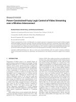
1.1 Basic configuration of marine control systems. . . . . . . . . . . . . . 9
2.1 Earth-fixed and body-fixed coo rdinate frames. . . . . . . . . . . . . . 21
2.2 A type-1 FLS. . . . . . . . . . . . . . . . . . . . . . . . . . . . . . . . 25
2.3 Vertical-slice of a type-2 fuzzy set. . . . . . . . . . . . . . . . . . . . . 29
2.4 Vertical-slice of an interval type-2 fuzzy set. . . . . . . . . . . . . . . 30
2.5 A singleton interval type-2 FLS. . . . . . . . . . . . . . . . . . . . . . 31
2.6 Pictorial description of input and antecedent operation for a singleton
interval type-2 fuzzy logic system. . . . . . . . . . . . . . . . . . . . . 3 3
3.1 Closed-loop equivalent representation for DP. . . . . . . . . . . . . . 45
3.2 Primary membership functions of the antecedent IT2 fuzzy sets. . . . 49
3.3 Regulation errors of indirect adaptive IT2 FLC f or DP. . . . . . . . . 51
3.4 Norms of the adapted weighting vectors for indirect adaptive IT2 F L C. 52
3.5 Regulation errors of indirect adaptive IT2 FLC with different control
gains for DP. . . . . . . . . . . . . . . . . . . . . . . . . . . . . . . . 53
3.6 Regulation errors of indirect adaptive IT2 FLC and PD controller for
DP. . . . . . . . . . . . . . . . . . . . . . . . . . . . . . . . . . . . . . 55
xi
3.7 Regulation errors of indirect adaptive IT2 and type-1 FLC for D P. . . 57
4.1 The measured vessel motion as the sum of the LF and WF motion. . 62
4.2 Block diagram of the adaptive IT2 fuzzy observer. . . . . . . . . . . . 6 8
4.3 Block diagram of the observer error dynamics. . . . . . . . . . . . . . 69
4.4 Bode diagram of the transfer function h
i
(s) when
φ
i
k
3i
k
4i
< ω
0i
< ω
ci
. . 73
4.5 Actual and estimated LF motion of adaptive IT2 fuzzy observer. . . . 81
4.6 Actual and estimated velocities of adaptive IT2 fuzzy observer. . . . . 82
4.7 Actual and estimated WF motion of adaptive IT2 fuzzy o bserver. . . 83
4.8 Estimation errors of LF motion for different observer gains. . . . . . . 84
4.9 Estimation errors of velocity for different observer gains . . . . . . . . 85
4.10 Estimation errors of WF motion for different observer gains. . . . . . 86
4.11 Estimation errors of LF motion for two observers. . . . . . . . . . . . 90
4.12 Estimation errors of velocity for two observers. . . . . . . . . . . . . . 91
4.13 Estimation errors of WF motion for two observers. . . . . . . . . . . . 92
5.1 Overall scheme o f indirect adaptive IT2 FLC for tracking control. . . 97
5.2 Overall scheme o f direct adaptive IT2 FLC for tracking control. . . . 99
5.3 Closed-loop equivalent representation for tracking control. . . . . . . 102
5.4 The desired and actual trajectory of the container ship under indirect
adaptive IT2 FLC. . . . . . . . . . . . . . . . . . . . . . . . . . . . . 106
5.5 The desired and actual trajectory of the container ship under direct
adaptive IT2 FLC. . . . . . . . . . . . . . . . . . . . . . . . . . . . . 107
xii
5.6 Tracking errors of indirect adaptive IT2 FLC for tracking control. . . 108
5.7 Tracking errors of direct adaptive IT2 FLC for tracking control. . . . 109
5.8 Tracking errors of indirect adaptive IT2 FLCs with different control
gains for tracking control. . . . . . . . . . . . . . . . . . . . . . . . . 112
5.9 Tracking errors of direct adaptive IT2 FLCs with different control gains
for tracking control. . . . . . . . . . . . . . . . . . . . . . . . . . . . . 113
5.10 Tracking errors of indirect adaptive type-1 a nd IT2 FLCs for tracking
control. . . . . . . . . . . . . . . . . . . . . . . . . . . . . . . . . . . 115
5.11 Tracking errors of direct adaptive type-1 and IT2 FLCs for tracking
control. . . . . . . . . . . . . . . . . . . . . . . . . . . . . . . . . . . 116
6.1 The desired and actual trajectory of the container ship under state
feedback fault-tolerant adaptive backstepping IT2 FLC. . . . . . . . . 135
6.2 Tracking errors of state feedback adaptive backstepping IT2 FLC. . . 136
6.3 Tracking errors of fault-tolerant adaptive backstepping IT2 FLC with
different control gains. . . . . . . . . . . . . . . . . . . . . . . . . . . 140
6.4 Tracking errors of output feedback adaptive backstepping IT2 FLC. . 143
6.5 The errors
˜
ν between actual velocity signals and their estimates for
four output feedback control cases. . . . . . . . . . . . . . . . . . . . 14 4
xiii
List of Tables
2.1 The notation of SNAME for marine vessels. . . . . . . . . . . . . . . 21
3.1 Main particulars of the S-175. . . . . . . . . . . . . . . . . . . . . . . 48
3.2 ITAE of adaptive type-1 and IT2 FLCs for DP. . . . . . . . . . . . . 58
5.1 ITAE of adaptive type-1 and IT2 FLCs for tracking control. . . . . . 118
xiv
Chapter 1
Introdu ction
As the major source of energy powering the world, fossil f uels have been contributing
to the growth of the global economy. With the demand for fo ssil fuels increasing
over the years, the exploration and exploitation of these energy sources have been
moving from land to the deep sea. This has brought a bout an era of offshore oil and
gas industry. Offshore oil and gas industry involves different kinds of equipments
to perform various missions. One crucial equipment is marine vessels, which include
drilling rigs, shuttle tankers, cable/pipe layers, floating production, storage, and of-
floading systems (FPSOs), crane and heavy lift vessels, and multi-purpose vessels. A
marine vessel may comprise sub-systems such as the main structure, marine control
system, power system, propulsion system, measurement system, equipment system
and auxiliary system. Among all these systems, the marine control system is essen-
tial to guarantee that sea operations such as deep sea oil drilling, installation and
intervention, oil production, storage and offloading, and cable/pipe laying are p er-
formed as planned. To increase the safety and efficiency of the sea operations, more
advanced marine control systems are necessary. One main factor that impedes the
performance of marine control systems is the hydrodynamic disturbances generated
by wind-induced waves and associated uncertainties. To handle the complex hydro-
dynamic disturbances and the uncertainties, advanced control algorithm is applied
1
to marine control system design in dynamic positioning (DP) and tracking control of
these marine vessels.
In the remainder of this chapter, a detailed exposition of the background a nd
motivation, as well as the objectives and scope, and organization of this thesis are
provided. For clarity of presentation, the background and motivation is separated
into two parts, namely Marine Control Systems and Interval Type-2 Fuzzy Logic. In
each part, the related works and background knowledge that motivate the research
in this thesis are discussed in detail.
1.1 Marine Control Systems
The history of vessel control starts with the invention of the gyrocompass in 1908.
The gyrocompass was the basic instrument in the first feedback control system for
heading control of vessels, and today these devices are known as autopilots. In 1970s,
local area vessel positioning systems like hydro acoustic reference systems, hyperbolic
radio navigation systems, and local electromagnetic distance measuring systems were
introduced. These systems together with new results in feedback control resulted in
new applications like DP systems for vessels. In 1994, Navstar GPS was declared fully
operational although the first satellite was launched in 1974. Today, GPS receivers
are standard component in tracking control systems. Marine control systems and
their applications to marine vessels have become more and more popular due to the
developments in computer science, propulsion systems and modern sensor technol-
ogy. Other examples of commercially available systems are: attitude control systems
2
for underwater vehicles, fin and rudder-roll stabilization systems, buoyancy control
systems including trim and heel correction systems, propeller and thruster control
systems, and energy and power managements systems. In the following subsections
autopilots, DP systems and tracking control systems are described in details. After
that, a basic configuration of marine control systems for different control objectives
is introduced.
1.1.1 Autopilots
The autopilot or automatic pilot is a device which is used to control an aircraft, ship
or other vehicles without constant human intervention. The earliest autopilots could
do no more than maintain a fixed heading (course-keeping) and they are still in use
by smaller boats during routine cruising nowadays. For vessels, course-keeping is the
first application. However, modern autopilots can conduct more complex maneuvers
like turning, docking operations and even control inherently unstable vessels, e.g.
submarines and some large oil tankers.
The history of autopilot f or vessel started with Elmer Sperry (1860-1930), who
constructed the first automatic ship steering mechanism for course keeping in 1911
[1]. This device, which is referred to as the “Metal Mike”, was a gyroscope-guided
autopilot or a mechanical helmsman. Later in 1922, Nicholas Minorsky (1885 -1970)
presented a detailed analysis of a position feedback control system where he for mu-
lated a three-term control law which today is known as Proportional Integral Deriva-
tive (PID) control [2]. These three different behaviors were motivated by observing
3
the way in which a helmsman steered a ship. The autopilot systems of Sperry and
Minorsky are both single-input single-output control systems, where they compare
the desired heading with the measured heading and compute the rudder command.
In 1960-1961 the K alman filter was publised by Kalman [3] and Kalman and Bucy
[4]. Two years later in 1963, the theory o f Linear Quadratic Regulator controller wa s
develop ed, which motivated the application of Linear Quadratic Gaussian (LQ G) in
autopilot design [5–7]. With the help of LQG control technique, the autopilot sys-
tem became multi-input multi-output system, and the heading and position of a ship
could be controlled simultaneously. In addition to LQG and H
∞
control, other de-
sign techniques have been applied to ship autopilot design to obta in better control
performance, for instance nonlinear control theory [8].
1.1.2 Dynamic Positioning Systems
A DP system is defined by the class societies e.g. Det Norske Veritas (DNV), Amer-
ican Bureau of Shipping (ABS) and Lloyd’s Register (LRS or Lloyd’s), as a sys-
tem that maintains a vessels’s position and heading exclusively by means of active
thrusters. This is obtained either by installing tunnel thrusters in addition to the
main propellers, or by using azimuth thrusters, which can produce thrust in different
directions. In offshore oil and gas industry, dynamic positioning finds very wide ap-
plications. It is almost applicable to all the service vessels. Besides, it is also widely
applied to merchant vessels, cruise ships, yachts and fisheries to assist their docking
and driving operations.
4
The great success of PID-based autopilots, and the development of local area
positioning systems suggested that three decoupled PID controllers could be used to
control the motion of a ship in the surge, sway and yaw axes exclusively by means
of thrusters and propellers. The idea was tested in the 19 60s, and the invention was
referred to as a DP system. The first DP system was designed using conventional
PID controller in cascade with low pass and notch filters to suppress the wave-induced
motion compo nents [9]. The drawback of the PID controller in cascade with low pass
and notch filters is that additional phase lag and nonlinearities are introduced in the
closed-loop system. In 1976, a new model-based control concept utilizing stochastic
optimal control theory and Kalman filtering techniques was employed to reduce these
problems by Balchen et al. [10]. The Kalman filter is used to separate the low fre-
quency and wave frequency motion components such that only low frequency motion
is fed back. The reason behind this is that the vessel motion is in the low frequency
spectrum, and the high frequency wave motio n due to first order wave would cause
wear and tear of the actuators if it enters the feedback loop. Later extensions and
modifications o f this work have been reported by many authors such as Balchen et
al. [11], Fung and Grimble [12], Fossen et al. [13], Sørensen et al. [14], Volovodov
et al [15 ] and Perez and Donaire [16]. The major drawback of Kalman filter is that
the kinematic equations must be linearized about a set of yaw angles, typically 36
operating points in steps of 10
◦
. As a result, it is very difficult and time consum-
ing to tune the parameters of the Kalman filter. In the 1990s nonlinear controls for
DP were proposed by several research gro ups. Stephens et al [17] proposed fuzzy
controllers. Aarset et al. [18], Fossen and Grøvlen [19] and Bertin et al. [20] pro-
5
posed backstepping and nonlinear feedback linearization for DP. As nonlinear control
techniques were actively developed in 1990s [21]– [24], the linear Kalman filter be-
came an obstacle in the research community. To surmount this obstacle, a passive
nonlinear observer was proposed by Fossen and Strand [25]. One of the motivations
for using nonlinear passivity theory was that the passivity theory allows the control
algorithms to be decomposed into several simpler subsystems. Correspondingly the
number of observer tuning parameters were significantly reduced. As DP technology
became more mature, research efforts were put into the integration of vessel con-
trol systems and missions by including operational requirements into the design of
both the guidance systems and the controllers. Sørensen et al. recommended the
concept of optimal setpoint following for DP of deep-water drilling and intervention
vessel [26]. Leira et al. extended this work and proposed to use structural reliability
criteria of the drilling risers for the setpoint following [27]. Fossen and Strand pre-
sented the nonlinear passive weather optimal positioning control systems for ships and
rigs [28]. The impo r tance o f the DP control system for the closed-loop performance
of the station keeping operation is clearly demonstrated in several studies. Mor-
ishita and Cornet [29], Morishita et al. [30] and Tannuri et al. [31] have conducted
detailed performance studies of the DP operations f or shuttle tanker and FPSOs.
More recently, Sørensen et al. [32], Nguyen [33]– [35], and Nguyen and Sørensen [36]
proposed the design of supervisory switched hybrid controllers for DP that automat-
ically switch controllers according to whether the sea conditions is clam or choppy,
and from transit to station keeping operations. The main objective of the supervisory
switched control is to integrate a bunch of controllers into a hybrid DP system being
6
able to control a vessel to operate in varying environmental and operational condi-
tions. When there are time-varying hydrodynamic disturbances in marine vessels as
shown in [37, 38], the existing DP controllers may not be able to provide satisfac-
tory performance, and the passive nonlinear observer [2 5] which models time-varying
hydrodynamic disturbances as a first order Markov process may only handle slowly
varying component of the time-varying hydrodynamic disturbances. In this thesis,
to handle the time-varying hydrodynamic disturbances that are present in marine
vessels during DP controller and observer design, adaptive technique is applied. Tra-
ditional model-based adaptive control technique is not suitable since it is generally
useful only when dealing with systems in which the dynamics are linear in the pa-
rameters, the regressors are exactly known, and the uncertainties are parametric and
time-invariant [39,40]. Hence, approximation-based adaptive control [41]– [48], which
does not require parametric or functional certainty, is adopted to compensate for the
disturbances from environment. The approximators in approximation-based adaptive
technique utilize a standard regressor function whose configuration is independent of
the dynamic characteristics of the vessel model.
1.1.3 Tracking Control Systems
A tracking control system is a system that controls a vessel to track a reference
trajectory which is computed from the old to the new position or heading set point.
The transformation of the way points to a feasible path or trajectory is generally a
nonlinear optimization problem. In order to guide a vessel through a busy water way
7
or to perform sea operations like dredging operations, towing operations, cable/pipe
laying operations, tra cking control is necessary.
The successful application of LQG controllers to vessel autopilots and DP systems,
and t he availability of global navigation systems like GPS and GLONASS resulted
in a growing interest for trajectory tracking control [49]– [53]. The controller design
problem can be treated as a nonlinear control problem or solved by means of linear
theory [52]. When there are time-varying hydrodynamic disturbances presented in
marine vessels [37, 38], the trajectory tracking problem with these models for both
state feedback and output feedback control is challenging. Faults in auto mated pro-
cesses often cause undesired reactions of a controlled plant, and the consequences
could be damaging to the plant, to personnel or the environments. In order to im-
prove the reliability of auto mated processes, fa ult-tolerant control has been proposed
and studied as illustrated in [54] and [55]. As a passive fault-tolerant approach, back-
stepping control has been applied in vessel control problems as shown in [51] and [56].
Augmentation of active fault-tolerant components to the backstepping control would
improve its performance. In this thesis, to accommodat e faults such as changes of
the loading conditions and trimming of the vessels, and fa ilure of some parts of the
control law in the controller, fault-tolerant tracking control of vessels is investigated.
1.1.4 Basic Configuration
Various methods have been proposed for designing marine control systems used fo r
DP and trajectory tracking. While the design methodologies may differ, the basic
8
configurations are more or less based on the same principles [57 ], as exemplified in
Fig. 1.1. The functions of the main components are described below.
Figure 1.1: Basic configuration of marine control systems.
• Signal processing. All signals from the sensors should be analyzed and checked
by a separate signal processing module. This includes testing of the individual
signals and signal voting and weighting when redundant measurements are
available. The individual signal quality verification should comprise tests for
frozen signals, signal range and variance, and signal wild points. If an erroneous
signal is detected, the signal is rejected a nd not used. The resultant signals
from each sensor group should not contain any steps or discontinuities when
utilized in the system in order to ensure a safe o peration.
• Vessel observer. When measurements of parts of the vessel states are not
available, estimates of these vessel states must be computed from available
9